Unit - 5
Hidden Line and Surfaces
The hidden surface is used to remove the parts from the image of solid objects.
The hidden surface is disabled by using opaque material which obstructs the hidden parts and prevents us from seeing them.
The automatic elimination does not happen when the objects are projected onto the screen coordinate system.
To remove some part of the surface or object we need to apply a hidden line or hidden surface algorithm to such objects.
The algorithm operates on the different kinds of models.
The model will generate various forms of output or different complexities in images.
The geometric sorting algorithms are used for distinguishing the visible parts and invisible parts.
The hidden surface algorithm is generally used to exploit one or many coherence properties to increase efficiency.
Following are the algorithms that are used for hidden line surface detection.
It is a simple and straight forward method.
It reduces the size of databases, as only front or visible surfaces are stored.
The area that is facing the camera is only visible in the back face removal algorithm.
The objects on the backside are not visible.
The 50% of polygons are removed in this algorithm when it uses parallel projection.
When the perspective projection is used then more than 50% of polygons are removed.
If the objects are nearer the center of projection then some polygons are removed.
It is applied to individual objects.
It does not consider the interaction between various objects.
Many polygons are captured by the front face as they are closer to the viewer.
Hence for removing such faces back face removal algorithm is used.
When the projection takes place, there are two surfaces one is a visible front surface and the other is not a visible back surface.
Following is the mathematical representation of the back face removal algorithm.
N1 = (V2 - V1) (V3 - V2)
If N1 * P >= 0 visible and N1 * P < 0
Key Takeaways:
The area facing the camera is only visible to the back face detection algorithm.
By using the parallel projection, it can remove 50% of the polygons and by using perspective projection more than 50% polygon can be removed.
This method is applied to an individual object.
This method is mostly useful for objects which are closer to the viewer.
The mathematical formulae are used in the back-face removal algorithm.
N1 = (V2 - V1) (V3 - V2)
If N1 * P >= 0 visible and N1 * P < 0
It is also called a Z-buffer algorithm.
It is the simplest image-space algorithm.
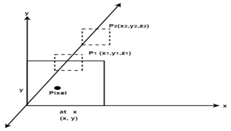
The depth of the object is computed by each pixel of the object displayed on the screen from this we get to know about how an object closer to the observer.
The record of intensity is also kept with the depth that should be displayed to show the object.
It is an extension of the frame buffer.
Two arrays are used for intensity and depth, the array is indexed by pixel coordinates (x,y).
Algorithm:
Initially set depth(x,y) as (1,0) and intensity (x,y) to background value.
Find all the pixels (x,y) that lies on the boundaries of the polygon when projected onto the screen.
To calculate pixel coordinates:
1. Calculate the depth z of the polygon at (x,y).
2. If z < depth (x,y) then this polygon lies closer to the observer else others are already recorded for this pixel.
3. Set depth (x,y) to z and intensity(x,y) to the value according to polygon shading.
4. If z > depth (x, y) then this polygon is new and no action is taken.
After all, polygons have been processed the intensity array will contain the solution.
This algorithm contains common features to the hidden surface algorithm.
It requires the representation of all opaque surfaces in scene polygon in the given figure below.
These polygons may be faces of polyhedral recorded in the model of the scene.

Fig. 1
Key Takeaways:
It is an image space algorithm known as the Z-buffer algorithm.
The depth of the object is calculated by the intensity.
The intensity is recorded in an array which is having the coordinates of pixels.
If z < depth (x,y) then this polygon lies closer to the observer else others are already recorded for this pixel.
If z > depth (x, y) then this polygon is new and no action is taken.
The A buffer method is a hidden face detection mechanism.
It is used in medium-scale virtual memory computer.
It is also referred to as an anti-aliased or area-averaged or accumulation buffer method.
This method is extended as a depth buffer or Z-buffer method.
The Z-buffer method is only used for the opaque object but not for the transparent object. A buffer method shows a positive result in this scenario.
A buffer requires more memory and different surface colors that are composed using it.
Each position of data in Z-buffer requires a linked list to refer to another position of data. But data is stored in an accumulation buffer in a buffer method.
These two fields are given for each position in a buffer:
The surface buffer in a buffer method includes:
Key Takeaways:
It is an extension of the Z-buffer algorithm also known as the anti-aliased or area-averaged or accumulation buffer method.
It shows the positive result in the various scenario.
Here two fields like depth and surface data field are used.
The disadvantage of A-buffer is it requires more memory and different surface colors.
It is an image space algorithm.
This method process one line at a time instead of one pixel at a time.
It follows the area of coherence mechanism.
In the scan line method, the active edge list is recorded as an edge list.
The edge list or edge table is the record of the coordinate of two endpoints.
Active edge list is edged a given scan line intersects during its sweep.
The active edge list should be sorted in increasing order of x. it is dynamic, growing, and shrinking.
This method deals with multiple surfaces. As the line intersects many surfaces.
The intersecting line will display the visible surface in the figure.
Therefore, the depth calculation will be done.
The surface area is rear to view plane is defined.
The value of the entered refresh buffer is shown as visibility of the surface.
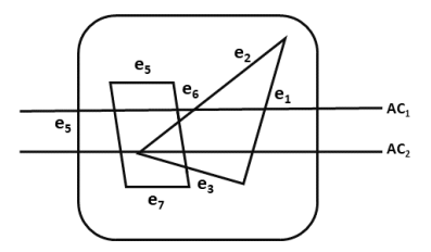
The following figure shows edges and active edge lists using the scan line method.
In the following figure, the active edge is displayed as AC1 which contains e1, e2, e5, e6 edges, and AC2 with e5, e6, e1 edges.

Fig. 2
Key Takeaways:
It can combine shading and hsr through a scan line algorithm.
It is an image space method for identifying visible surfaces.
From fig.5.5, no need for the depth information for one polygon in the AC1 line.
From fig. 5.5, needs depth information when there are more than one polygons as an AC2 line.
It is also called a lighting model or shading model.
It is used to calculate the intensity of light which is reflected at the given point on the surface.
The lighting effects depend on three factors:
Light source: the light sources can be a point source, parallel source, distributed source, etc.
Surface: the light falls on the surface part and reflects.
Observer: the position of the observer and the sensor spectrum sensitivities that also affect the light.
Following are the illumination models.
5.6.1 Ambient Light
This also referred to available lighting in an environment.
Suppose the observer is standing on the road facing the building with an exterior of glass and the sun rays are falling on the building reflecting from it and falling on the object under observation.
This is known as ambient illumination.
Where the source of light is indirect then it is referred to as ambient illumination.
The reflected intensity Iamb =Ka * Ia
Where Ka is the surface ambient reflectivity value which varies from 0 to 1, Ia is the ambient light intensity.
5.6.2 Diffuse Reflection
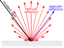
The diffuse reflection is the reflection of the rays that are scattered at many angles from the surface.
In the specular reflection, the ray incident on the surface is scattered at one angle only.
The surface of the reflection should have equal luminance when viewed from all directions lying in the half-space adjacent to the surface.
The surface can be plaster or fibers as paper, polycrystalline material.
The surface of reflection in diffuse reflection is rough or grainy.
The light source and the surface made an angle that shows the brightness of a point.
The reflected intensity Idiff of a point on the surface:
Idiff = Kd * Ip cos(Ꙫ) = Kd * Ip (N * L)
Where Ip is the point light intensity, Kd is the surface diffuse reflectivity value, N is the surface normal and L is the light direction.
The following figure shows the diffuse and specular reflection from the glossy surface.

Fig. 3
5.6.3 Specular Reflection
It is a regular reflection.
The specular reflection of light reflects from the surface like a mirror reflection.
The specular reflection contrasted with the diffuse reflection.
In specular reflection, the light is scattered from the surface in the range of the direction.
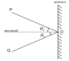
The following figure shows the coplanar condition of the specular reflection.

Fig. 4
5.6.4 Phong Model
It is an empirical model for specular reflection.
It is also referred to as Phong illumination or Phong lighting.
It is also known as Phong shading in 3D graphics.
The formula for the calculation of the reflected intensity I spec.
Ispec=W(Ꙫ) I * cos n (ф)
Where W(Ꙫ) is Ks, L is the light source, N is the normal surface, R is the direction of reflected ray, V is the direction of the observer, Ꙫ is the angle between L and R, ф be the angle between R and V.
Key Takeaways:
It is used to calculate the intensity of light which is reflected at the given point on the surface.
The lighting effects depend on three factors as light source, surface, and observer.
Some illumination models are in computer graphics as Ambient Light, Diffuse Reflection, Specular Reflection, and Phong Model.
For a single point light source, the combined diffuse and the specular reflection from the point on an illuminated surface as,
I=Idiff + Ispec
= Ka. Ia + Kd. I (N . L) + Kc . I (N . H)
If we place the more than one point source then we obtain the light reflection at any surface point by summing the contribution from the individual sources.
The warn model is a method used to simulate the lighting effects of the studio by controlling light intensity in a different direction.
The Phong model is used for sourcing the light which reflects on the surface.
The intensity is calculated by collecting the different directional selected values of the Phong exponent.
The warn model is used in light controlling, spotlighting, and also used by photographers to the simulation of light.
The light of the source is controlled by flaps.
The polygon’s surface having constant intensity.
Intensity is not affected by anything else in the world.
Intensity is not affected by the position or orientation of the polygon in the world
The attenuation is the property of light.
When the distance from the light increases the amount of illumination from the light source is decreased.
The attenuation property is applied to the point lights only where the directional lights are effectively at infinite distance.
Illumination is proportional to one over the square of distance which does not give a good result in graphics.
There is no attenuation follows with distance from the light source.
Color consideration is defined by color models.
It the range of colors that creates a set of primary colors.
There are two types of the color model as follows:
There are several color models are used in computer graphics.
RGB is the most commonly used for computer display.
CMYK is used for printing in graphics.
Shadow:
The shadow is visible by the viewer but not visible by the cover surfaces.
The problem in shadow is to compute for each point and each light source.
The shadow can be calculated by a hidden surface detection algorithm.
Following algorithms are used to calculate shadow.
Object and image precision algorithm
Two-pass Z-buffer shadow algorithm
Transparency:
The transparency surface produces two types of light as reflected light and transmitted light.
The relative contribution of transmitted light depends on the degree of transparency of the surface.
I = (1-k1) I1 + k1 . I2
Where k1 is the transmission coefficient
K1=0 for opaque surface
K1=1 if the surface is completely transparent
There are two types of transparency.
References:
1. Donald Hearn and M Pauline Baker, “Computer Graphics C Version”, Pearson Education
2. Foley, Vandam, Feiner, Hughes – “Computer Graphics principle”, Pearson Education.
3. Rogers, “Procedural Elements of Computer Graphics”, McGraw Hill
4. W. M. Newman, R. F. Sproull – “Principles of Interactive Computer Graphics” – Tata McGraw Hill.
5. Amrendra N Sinha And Arun D Udai,” Computer Graphics”, Tata McGraw Hill.
6. R.K. Maurya, “Computer Graphics” Wiley Dreamtech Publication.
7. M.C. Trivedi, NN Jani, Computer Graphics & Animations, Jaico Publications
8 Rishabh Anand, Computer Graphics- A practical Approach, Khanna Publishing House
9. Mukherjee, Fundamentals of Computer graphics & Multimedia, PHI Learning Private Limited.
10. Donald Hearn and M Pauline Baker, “Computer Graphics with OpenGL”, Pearson education