Unit – 4
Transport Layer
While the Data Link Layer needs the source-destination hosts' MAC addresses (48-bit addresses found within the Network Interface Card of any host machine) to correctly deliver a frame, the Transport Layer requires a Port number to correctly deliver data segments to the correct process among the multiple processes operating on a single host.
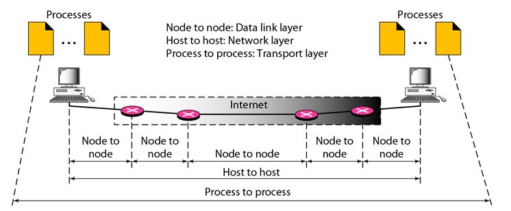
Fig 1: process to process delivery
UDP Protocol
In computer networking, the UDP stands for User Datagram Protocol. David P. Reed developed the UDP protocol in 1980. It is defined in RFC 768, and it is a part of the TCP/IP protocol, so it is a standard protocol over the internet. The UDP protocol allows the computer applications to send the messages in the form of datagrams from one machine to another machine over the Internet protocol (IP) network.
The UDP is an alternative communication protocol to the TCP protocol (transmission control protocol). Like TCP, UDP provides a set of rules that governs how the data should be exchanged over the internet. The UDP works by encapsulating the data into the packet and providing its own header information to the packet. Then, this UDP packet is encapsulated to the IP packet and sent off to its destination. Both the TCP and UDP protocols send the data over the internet protocol network, so it is also known as TCP/IP and UDP/IP.
There are many differences between these two protocols. UDP enables the process-to-process communication, whereas the TCP provides host to host communication. Since UDP sends the messages in the form of datagrams, it is considered the best-effort mode of communication. TCP sends the individual packets, so it is a reliable transport medium.
Another difference is that the TCP is a connection-oriented protocol whereas the UDP is a connectionless protocol as it does not require any virtual circuit to transfer the data. UDP also provides a different port number to distinguish different user requests and also provides the checksum capability to verify whether the complete data has arrived or not; the IP layer does not provide these two services.
Features of UDP protocol
The following are the features of the UDP protocol:
● Transport layer protocol
UDP is the simplest transport layer communication protocol. It contains a minimum amount of communication mechanisms. It is considered an unreliable protocol, and it is based on best-effort delivery services. UDP provides no acknowledgment mechanism, which means that the receiver does not send the acknowledgment for the received packet, and the sender also does not wait for the acknowledgment for the packet that it has sent.
● Connectionless
The UDP is a connectionless protocol as it does not create a virtual path to transfer the data. It does not use the virtual path, so packets are sent in different paths between the sender and the receiver, which leads to the loss of packets or received out of order.
Ordered delivery of data is not guaranteed.
In the case of UDP, the datagrams sent in some order will be received in the same order is not guaranteed as the datagrams are not numbered.
● Ports
The UDP protocol uses different port numbers so that the data can be sent to the correct destination. The port numbers are defined between 0 and 1023.
● Faster transmission
UDP enables faster transmission as it is a connectionless protocol, i.e., no virtual path is required to transfer the data. But there is a chance that the individual packet is lost, which affects the transmission quality. On the other hand, if the packet is lost in TCP connection, that packet will be resent, so it guarantees the delivery of the data packets.
● Acknowledgment mechanism
The UDP does have an acknowledgment mechanism, i.e., there is no handshaking between the UDP sender and UDP receiver. If the message is sent in TCP, then the receiver acknowledges that I am ready, then the sender sends the data. In the case of TCP, the handshaking occurs between the sender and the receiver, whereas in UDP, there is no handshaking between the sender and the receiver.
● Segments are handled independently.
Each UDP segment is handled individually by others as each segment takes a different path to reach the destination. The UDP segments can be lost or delivered out of order to reach the destination as there is no connection setup between the sender and the receiver.
● Stateless
It is a stateless protocol that means that the sender does not get the acknowledgement for the packet which has been sent.
Why do we require the UDP protocol?
As we know that the UDP is an unreliable protocol, but we still require a UDP protocol in some cases. The UDP is deployed where the packets require a large amount of bandwidth along with the actual data. For example, in video streaming, acknowledging thousands of packets is troublesome and wastes a lot of bandwidth. In the case of video streaming, the loss of some packets couldn't create a problem, and it can also be ignored.
UDP Header Format

Fig 2: UDP header format
In UDP, the header size is 8 bytes, and the packet size is up to 65,535 bytes. But this packet size is not possible as the data needs to be encapsulated in the IP datagram, and an IP packet, the header size can be 20 bytes; therefore, the maximum of UDP would be 65,535 minus 20. The size of the data that the UDP packet can carry would be 65,535 minus 28 as 8 bytes for the header of the UDP packet and 20 bytes for IP header.
The UDP header contains four fields:
● Source port number: It is 16-bit information that identifies which port is going to send the packet.
● Destination port number: It identifies which port is going to accept the information. It is 16-bit information which is used to identify application-level service on the destination machine.
● Length: It is a 16-bit field that specifies the entire length of the UDP packet that includes the header also. The minimum value would be 8-byte as the size of the header is 8 bytes.
● Checksum: It is a 16-bits field, and it is an optional field. This checksum field checks whether the information is accurate or not as there is the possibility that the information can be corrupted while transmission. It is an optional field, which means that it depends upon the application, whether it wants to write the checksum or not. If it does not want to write the checksum, then all the 16 bits are zero; otherwise, it writes the checksum. In UDP, the checksum field is applied to the entire packet, i.e., header as well as data part whereas, in IP, the checksum field is applied to only the header field.
Concept of Queuing in UDP protocol
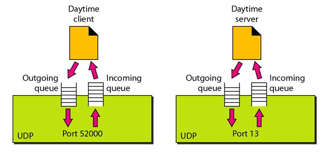
Fig 3: Concept of Queuing in UDP protocol
In UDP protocol, numbers are used to distinguish the different processes on a server and client. We know that UDP provides a process-to-process communication. The client generates the processes that need services while the server generates the processes that provide services. The queues are available for both the processes, i.e., two queues for each process. The first queue is the incoming queue that receives the messages, and the second one is the outgoing queue that sends the messages. The queue functions when the process is running. If the process is terminated then the queue will also get destroyed.
UDP handles the sending and receiving of the UDP packets with the help of the following components:
● Input queue: The UDP packet uses a set of queues for each process.
● Input module: This module takes the user datagram from the IP, and then it finds the information from the control block table of the same port. If it finds the entry in the control block table with the same port as the user datagram, it enqueues the data.
● Control Block Module: It manages the control block table.
● Control Block Table: The control block table contains the entry of open ports.
● Output module: The output module creates and sends the user datagram.
Several processes want to use the services of UDP. The UDP multiplexes and demultiplexes the processes so that the multiple processes can run on a single host.
Limitations
● It provides an unreliable connection delivery service. It does not provide any services of IP except that it provides process-to-process communication.
● The UDP message can be lost, delayed, duplicated, or can be out of order.
● It does not provide a reliable transport delivery service. It does not provide any acknowledgment or flow control mechanism. However, it does provide error control to some extent.
Advantages
● It produces a minimal number of overheads.
TCP
TCP stands for Transmission Control Protocol. It is a transport layer protocol that facilitates the transmission of packets from source to destination. It is a connection-oriented protocol that means it establishes the connection prior to the communication that occurs between the computing devices in a network. This protocol is used with an IP protocol, so together, they are referred to as a TCP/IP.
The main functionality of the TCP is to take the data from the application layer. Then it divides the data into several packets, provides numbers to these packets, and finally transmits these packets to the destination. The TCP, on the other side, will reassemble the packets and transmit them to the application layer. As we know that TCP is a connection-oriented protocol, so the connection will remain established until the communication is not completed between the sender and the receiver.
Features of TCP protocol
The following are the features of a TCP protocol:
● Transport Layer Protocol
TCP is a transport layer protocol as it is used in transmitting the data from the sender to the receiver.
● Reliable
TCP is a reliable protocol as it follows the flow and error control mechanism. It also supports the acknowledgment mechanism, which checks the state and sound arrival of the data. In the acknowledgment mechanism, the receiver sends either positive or negative acknowledgment to the sender so that the sender can get to know whether the data packet has been received or needs to resend.
● Order of the data is maintained
This protocol ensures that the data reaches the intended receiver in the same order in which it is sent. It orders and numbers each segment so that the TCP layer on the destination side can reassemble them based on their ordering.
● Connection-oriented
It is a connection-oriented service that means the data exchange occurs only after the connection establishment. When the data transfer is completed, then the connection will get terminated.
● Full duplex
It is a full-duplex means that the data can transfer in both directions at the same time.
● Stream-oriented
TCP is a stream-oriented protocol as it allows the sender to send the data in the form of a stream of bytes and also allows the receiver to accept the data in the form of a stream of bytes. TCP creates an environment in which both the sender and receiver are connected by an imaginary tube known as a virtual circuit. This virtual circuit carries the stream of bytes across the internet.
Need of Transport Control Protocol
In the layered architecture of a network model, the whole task is divided into smaller tasks. Each task is assigned to a particular layer that processes the task. In the TCP/IP model, five layers are application layer, transport layer, network layer, data link layer, and physical layer. The transport layer has a critical role in providing end-to-end communication to the direct application processes. It creates 65,000 ports so that the multiple applications can be accessed at the same time. It takes the data from the upper layer, and it divides the data into smaller packets and then transmits them to the network layer.
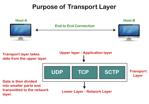
Fig 4: Purpose of transport layer
Working of TCP
In TCP, the connection is established by using three-way handshaking. The client sends the segment with its sequence number. The server, in return, sends its segment with its own sequence number as well as the acknowledgement sequence, which is one more than the client sequence number. When the client receives the acknowledgment of its segment, then it sends the acknowledgment to the server. In this way, the connection is established between the client and the server.
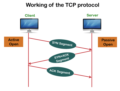
Fig 5: Working of the TCP protocol
Advantages of TCP
● It provides a connection-oriented reliable service, which means that it guarantees the delivery of data packets. If the data packet is lost across the network, then the TCP will resend the lost packets.
● It provides a flow control mechanism using a sliding window protocol.
● It provides error detection by using checksum and error control by using Go Back or ARP protocol.
● It eliminates the congestion by using a network congestion avoidance algorithm that includes various schemes such as additive increase/multiplicative decrease (AIMD), slow start, and congestion window.
Disadvantage of TCP
It increases a large amount of overhead as each segment gets its own TCP header, so fragmentation by the router increases the overhead.
TCP Header format
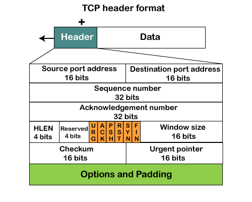
Fig 6: TCP header format
● Source port: It defines the port of the application, which is sending the data. So, this field contains the source port address, which is 16 bits.
● Destination port: It defines the port of the application on the receiving side. So, this field contains the destination port address, which is 16 bits.
● Sequence number: This field contains the sequence number of data bytes in a particular session.
● Acknowledgment number: When the ACK flag is set, then this contains the next sequence number of the data byte and works as an acknowledgment for the previous data received. For example, if the receiver receives the segment number 'x', then it responds 'x+1' as an acknowledgment number.
● HLEN: It specifies the length of the header indicated by the 4-byte words in the header. The size of the header lies between 20 and 60 bytes. Therefore, the value of this field would lie between 5 and 15.
● Reserved: It is a 4-bit field reserved for future use, and by default, all are set to zero.
● Flags
There are six control bits or flags:
● Window size
It is a 16-bit field. It contains the size of data that the receiver can accept. This field is used for the flow control between the sender and receiver and also determines the amount of buffer allocated by the receiver for a segment. The value of this field is determined by the receiver.
● Checksum
It is a 16-bit field. This field is optional in UDP, but in the case of TCP/IP, this field is mandatory.
● Urgent pointer
It is a pointer that points to the urgent data byte if the URG flag is set to 1. It defines a value that will be added to the sequence number to get the sequence number of the last urgent byte.
● Options
It provides additional options. The optional field is represented in 32-bits. If this field contains the data less than 32-bit, then padding is required to obtain the remaining bits.
What is a TCP port?
The TCP port is a unique number assigned to different applications. For example, we have opened the email and games applications on our computer; through email application, we want to send the mail to the host, and through games application, we want to play the online games. In order to do all these tasks, different unique numbers are assigned to these applications. Each protocol and address have a port known as a port number. The TCP (Transmission control protocol) and UDP (User Datagram Protocol) protocols mainly use the port numbers.
A port number is a unique identifier used with an IP address. A port is a 16-bit unsigned integer, and the total number of ports available in the TCP/IP model is 65,535 ports. Therefore, the range of port numbers is 0 to 65535. In the case of TCP, the zero-port number is reserved and cannot be used, whereas, in UDP, the zero port is not available. IANA (Internet Assigned Numbers Authority) is a standard body that assigns the port numbers.
Example of port number:
192.168.1.100: 7
In the above case, 192.168.1.100 is an IP address, and 7 is a port number.
To access a particular service, the port number is used with an IP address. The range from 0 to 1023 port numbers are reserved for the standard protocols, and the other port numbers are user-defined.
Why do we require port numbers?
A single client can have multiple connections with the same server or multiple servers. The client may be running multiple applications at the same time. When the client tries to access some service, then the IP address is not sufficient to access the service. To access the service from a server, the port number is required. So, the transport layer plays a major role in providing multiple communication between these applications by assigning a port number to the applications.
Classification of port numbers
The port numbers are divided into three categories:
● Well-known ports
● Registered ports
● Dynamic ports
Well-known ports
The range of well-known ports is 0 to 1023. The well-known ports are used with those protocols that serve common applications and services such as HTTP (Hypertext transfer protocol), IMAP (Internet Message Access Protocol), SMTP (Simple Mail Transfer Protocol), etc. For example, we want to visit some websites on an internet; then, we use http protocol; the http is available with a port number 80, which means that when we use http protocol with an application then it gets port number 80. It is defined that whenever http protocol is used, then port number 80 will be used. Similarly, with other protocols such as SMTP, IMAP, well-known ports are defined. The remaining port numbers are used for random applications.
Registered ports
The range of registered ports is 1024 to 49151. The registered ports are used for the user processes. These processes are individual applications rather than the common applications that have a well-known port.
Dynamic ports
The range of dynamic ports is 49152 to 65535. Another name of the dynamic port is ephemeral ports. These port numbers are assigned to the client application dynamically when a client creates a connection. The dynamic port is identified when the client initiates the connection, whereas the client knows the well-known port prior to the connection. This port is not known to the client when the client connects to the service.
TCP and UDP header
As we know that both TCP and UDP contain source and destination port numbers, and these port numbers are used to identify the application or a server both at the source and the destination side. Both TCP and UDP use port numbers to pass the information to the upper layers.
Let's understand this scenario.
Suppose a client is accessing a web page. The TCP header contains both the source and destination port.
Client-side
Source Port: The source port defines an application to which the TCP segment belongs to, and this port number is dynamically assigned by the client. This is basically a process to which the port number is assigned.
Destination port: The destination port identifies the location of the service on the server so that the server can serve the request of the client.
Server-side
Source port: It defines the application from where the TCP segment came from.
Destination port: It defines the application to which the TCP segment is going to.
In the above case, two processes are used:
Encapsulation: Port numbers are used by the sender to tell the receiver which application it should use for the data.
Decapsulation: Port numbers are used by the receiver to identify which application it should send the data to.
Let's understand the above example by using all three ports, i.e., well-known port, registered port, and dynamic port.
First, we look at a well-known port.
The well-known ports are the ports that serve the common services and applications like http, ftp, smtp, etc. Here, the client uses a well-known port as a destination port while the server uses a well-known port as a source port. For example, the client sends an http request, then, in this case, the destination port would be 80, whereas the http server is serving the request so its source port number would be 80.
Now, we look at the registered port.
The registered port is assigned to the non-common applications. Lots of vendor applications use this port. Like the well-known port, client uses this port as a destination port whereas the server uses this port as a source port.
At the end, we see how dynamic ports work in this scenario.
The dynamic port is the port that is dynamically assigned to the client application when initiating a connection. In this case, the client uses a dynamic port as a source port, whereas the server uses a dynamic port as a destination port. For example, the client sends an http request; then in this case, the destination port would be 80 as it is a http request, and the source port will only be assigned by the client. When the server serves the request, then the source port would be 80 as it is an http server, and the destination port would be the same as the source port of the client. The registered port can also be used in place of a dynamic port.
Let's look at the below example.
Suppose the client is communicating with a server, and sending the http request. So, the client sends the TCP segment to the well-known port, i.e., 80 of the HTTP protocols. In this case, the destination port would be 80 and suppose the source port assigned dynamically by the client is 1028. When the server responds, the destination port is 1028 as the source port defined by the client is 1028, and the source port at the server end would be 80 as the HTTP server is responding to the request of the client.
Key takeaways:
Multiplexing is a technique for combining two or more data sources into a single session. When a TCP client establishes a connection with Server, it often uses a specific port number to identify the application process. The client uses a port number that is created at random from private port number pools.
TCP Multiplexing allows a client to communicate with multiple application processes in a single session. When a client requests a web page that includes a variety of data types (HTTP, SMTP, FTP, and so on), the TCP session timeout is increased and the session is held open for longer to prevent the three-way handshake overhead.
The client device will now receive several connections via a single virtual link. If the timeout is too long, these virtual links are not good for Servers.
Several processes can be needed to send packets at the sender site. At any given time, however, there is only one transport layer protocol. Multiplexing is needed since this is a many-to-one relationship. The protocol accepts messages from a variety of processes, which are identified by their port numbers. The transport layer transfers the packet to the network layer after inserting the header.
Multiplexing is the method of gathering data from multiple sender application processes, wrapping it in a header, and delivering it all at once to the intended recipient.
The transport layer may use multiplexing to increase transmission performance. Figure shows two methods of multiplexing at this layer.
Multiplexing can take place in one of two ways:
Upward multiplexing
Multiple transport layer links using the same network link is known as upward multiplexing. The transport layer uses upward multiplexing to send several transmissions bound for the same destination along the same direction, making it more cost-effective.
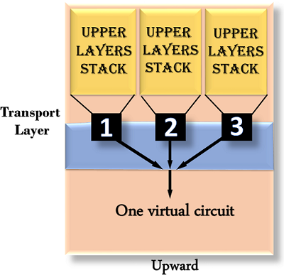
Fig 7: upward
Downward multiplexing
Downward multiplexing refers to the use of multiple network links through a single transport layer link. Downward multiplexing allows the transport layer to divide a link into multiple paths in order to increase throughput. When networks have a low or sluggish capacity, this form of multiplexing is used.
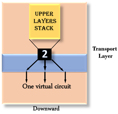
Fig 8: downward multiplexing
Key takeaways
The Server/Client model governs TCP communication. The client initiates the connection, which is either accepted or rejected by the server. Link management is accomplished by three-way handshaking.
An active open to a server is the first step in establishing a TCP link. The two sides engage in a message exchange to create the link, assuming the server did a passive open earlier. The two sides do not begin sending data until the link establishment process is complete. Similarly, when a participant finishes sending data, it closes one of the link's directions, causing TCP to send a round of connection termination messages.
There are two methods for delivering end-to-end services: connection-oriented and connectionless. From the two modes, the link-oriented mode is the most widely used. A connection-oriented protocol defines a virtual circuit or pathway between the sender and receiver via the internal network. This route is then used to send all of the packets that make up a post.
Connection-oriented services are usually considered secure because they use a single pathway for the entire message. This simplifies the acknowledgement process and allows for the retransmission of damaged or lost frames.
Link configuration is asymmetric (one side opens passively while the other opens actively), but connection teardown is symmetric (each side has to close the connection independently). As a result, one side may have completed a close, meaning it can no longer send data, while the other side maintains the other half of the bidirectional link open and continues to send data.
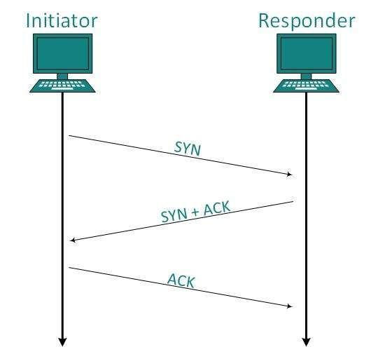
Fig 9: Connection management
Establishment
The client establishes the link and sends the fragment, which includes a Sequence number. The server responds with its own Sequence number and an ACK of the client's section that is one higher than the client's Sequence number. Client sends an acknowledgment of Server's answer after receiving ACK of its segment.
Release
With the FIN flag set to 1, either the server or the client may submit a TCP line. The path of TCP communication is closed and the link is released when the receiving end responds with Acknowledging FIN.
Key takeaway:
Flow control is used to keep the sender from sending too much data to the recipient. When a receiver is overwhelmed with data, it discards packets and requests that they be retransmitted. As a result, network congestion increases, lowering system performance.
Flow regulation is handled by the transport layer. It employs the sliding window protocol, which improves data transmission efficiency while still controlling data flow to avoid overloading the receiver. Instead of being frame-oriented, the sliding window protocol is byte-oriented.
The TCP/IP model's transport layer provides a flow control mechanism between the adjacent layers. TCP also employs flow control strategies to avoid data loss caused by a fast sender and a slow receiver. It employs the sliding window protocol, in which the receiver sends a window back to the sender indicating the maximum amount of data it will accept.

Fig 10: flow control
Retransmission
The following are the two schemes that are used:
● Fast retransmit
● Fast recovery
TCP starts a timer when a source sends a segment. If this value is set too low, many unwanted transmissions can occur. When the threshold is set too high, bandwidth is wasted, resulting in lower throughput. The timer value in the Quick Retransmit scheme is set higher than the RTT. As a result, the sender will sense segment loss before the timer runs out. This scheme assumes that if a packet is lost, the sender will receive several ACKs.
Round Trip Time (RTT): The segments can travel across multiple intermediate networks and via multiple routers in an Internet environment. Different delays may exist between networks and routers, and these delays may change over time. As a result, the RTT is also variable. It's difficult to set timers because of this. TCP uses an adaptive retransmission algorithm to allow for varying timers. It functions like this:
Key takeaway:
To monitor the flow of data coming from the sending application program, TCP uses two buffers and one window. Data is generated and written to the buffer by the application program. The sender creates a window in this buffer and sends segments as long as the window size is not zero.
The TCP receiver also has a buffer. It receives data, checks it, and stores it in a buffer for the receiving application program to ingest. A sliding window is used to increase the efficiency of data transmission while still controlling the flow of data so that the destination is not overburdened. The sliding window of TCP is byte-oriented.
TCP sliding window
The source isn't required to submit the entire window's worth of data. The destination has the ability to change the size of the window. At any time, the destination can submit an acknowledgment.
Silly window syndrome
Another issue that can degrade TCP efficiency is Silly Window Syndrome. This problem arises when the sender sends data in large blocks, but the receiver's interactive program reads data one byte at a time.
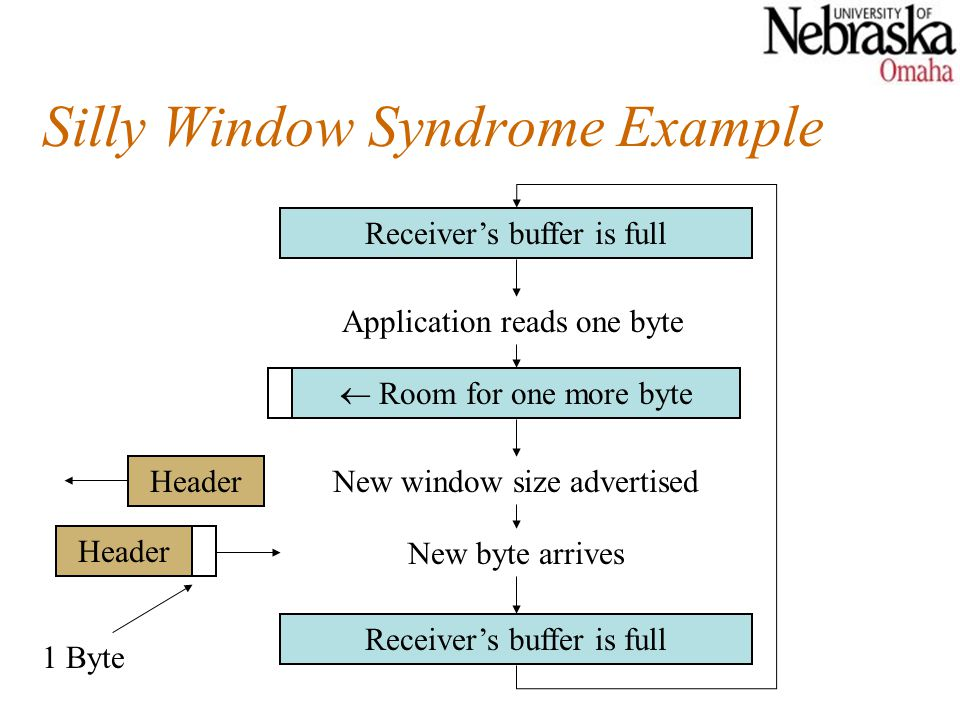
Fig 11: silly window syndrome
Solution to Silly Window Syndrome
The following was proposed as a solution to the silly window syndrome:
It was suggested that the receiver not submit a 1byte window update.
Instead, it must first wait until it has a significant amount of buffer space before sending the window update. To be more precise, the receiver should not submit a window update until it can manage the maximum window size it advertised when establishing the link, or until its buffer is half full, whichever comes first.
The sender may also be able to assist in improving the situation. It should not send small fragments, but rather wait and send a complete segment, or at least one that is half the size of the receiver's buffer.
Key takeaway:
Congestion control refers to procedures and processes that can either avoid congestion from occurring or eliminate congestion that has already occurred.
Congestion happens when a large volume of data is fed into a device that is not capable of handling it. TCP uses the Window function to manage congestion. TCP specifies a window size, which tells the other end how much data to send in each data segment.
Hosts would send their packets into the internet as quickly as the advertised window would allow, congestion would occur at certain routers (causing packets to be dropped), and the hosts would time out and retransmit their packets, resulting in even more congestion.
TCP congestion management works by allowing each source to decide how much network capacity is available, allowing it to determine how many packets it can safely send through the network.
For congestion management, TCP can use one of three algorithms:
● Additive increase, Multiplicative Decrease
● Slow Start
● Timeout React
Adaptive increase / Multiplicative Decrease
TCP creates a new state variable called Congestion Window for each link, which the source uses to restrict the amount of data it may have in transit at any given time. Congestion control's advertised window is the inverse of flow control's advertised window. The maximum number of bytes of unacknowledged data permitted by TCP is now equal to the lesser of the congestion window and the advertised window. The successful window of TCP has been updated as follows:
Max Window =MIN (Congestion Window, Advertised Window)
Effective Window =Max Window – (Last Byte Sent- Last Byte Acked)
Slow Start
When the source is running close to the network's usable power, the additive increase process outlined above is the right approach to take, but it takes too long to scale up a link when it is starting from scratch. As a result, TCP t provides the second mechanism, ironically dubbed slow chat, which is used to rapidly increase the congestion window from a cold start. Slowly increasing the congestion window exponentially rather than linearly increases the congestion window exponentially.
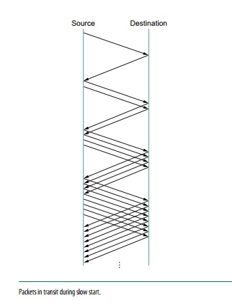
Fig 12: packet in transit during slow start
Congestion Window is initially set to one packet by the source. When TCCP receives the ACK for this packet, it adds 1 to the Congestion Window and sends two packets. TCP increases the Congestion Window by 2-one for each ACK after receiving the corresponding two ACKs, and then sends four packets. As a result, TCP essentially doubles the number of packets in transit with each RTT.
Slow start runs will occur in two separate scenarios. The first occurs at the start of a link, when the source has no idea how many packets it will be able to send in a given amount of time. Slow start tends to double Congestion Window for each RTT until there is a loss, at which point a timeout causes a multiplicative decrease, causing Congestion Window to be divided by two.
The second instance of slow start is when the link goes dead while waiting for a timeout to occur.
Key takeaway:
QoS is an overall performance measure of the computer network. Quality of Service (QoS) is a group of technologies that work together on a network to ensure that high-priority applications and traffic are reliably delivered even when network capacity is reduced. This is accomplished using QoS technologies, which provide differential handling and power allocation of individual network traffic flows.
Multimedia applications that combine audio, video, and data should be supported by the network. It should be able to do so with enough bandwidth. The delivery timeliness can be extremely critical. Real-time apps are applications that are responsive to data timeliness. The information should be provided in a timely manner. Help quality of service refers to a network that can deliver these various levels of service.
Bandwidth (throughput), latency (delay), jitter (variance in latency), and error rate are all important QoS metrics. As a result, QoS is especially important for high-bandwidth, real-time traffic like VoIP, video conferencing, and video-on-demand, which are sensitive to latency and jitter.
Important flow characteristics of the QoS are given below:
1. Reliability
If a packet gets lost or acknowledgement is not received (at sender), the re-transmission of data will be needed. This decreases the reliability.
The importance of reliability can differ according to the application.
Example: E- mail and file transfer need to have a reliable transmission as compared to that of an audio conferencing.
2. Delay
Delay of a message from source to destination is a very important characteristic. However, delay can be tolerated differently by the different applications.
Example: The time delay cannot be tolerated in audio conferencing (needs a minimum time delay), while the time delay in the email or file transfer has less importance.
3. Jitter
The jitter is the variation in the packet delay.
If the difference between delays is large, then it is called a high jitter. On the contrary, if the difference between delays is small, it is known as low jitter.
Example:
Case1: If 3 packets are sent at times 0, 1, 2 and received at 10, 11, 12. Here, the delay is the same for all packets and it is acceptable for the telephonic conversation.
Case2: If 3 packets 0, 1, 2 are sent and received at 31, 34, 39, so the delay is different for all packets. In this case, the time delay is not acceptable for the telephonic conversation.
4. Bandwidth
Different applications need different bandwidth.
Example: Video conferencing needs more bandwidth in comparison to that of sending an e-mail.
Integrated Services and Differentiated Service
These two models are designed to provide Quality of Service (QoS) in the network.
1. Integrated Services (IntServ)
Integrated service is a flow-based QoS model and designed for IP.
In integrated services, a user needs to create a flow in the network, from source to destination and needs to inform all routers (every router in the system implements IntServ) of the resource requirement.
Following are the steps to understand how integrated services work.
I) Resource Reservation Protocol (RSVP)
An IP is connectionless, datagram, packet-switching protocol. To implement a flow-based model, a signaling protocol is used to run over IP, which provides the signaling mechanism to make reservations (every application needs assurance to make reservation), this protocol is called RSVP.
ii) Flow Specification
While making reservations, resources need to define the flow specification. The flow specification has two parts:
a) Resource specification
It defines the resources that the flow needs to reserve. For example: Buffer, bandwidth, etc.
b) Traffic specification
It defines the traffic categorization of the flow.
iii) Admit or deny
After receiving the flow specification from an application, the router decides to admit or deny the service and the decision can be taken based on the previous commitments of the router and current availability of the resource.
Classification of services
The two classes of services to define Integrated Services are:
a) Guaranteed Service Class
This service guarantees that the packets arrive within a specific delivery time and not discarded, if the traffic flow maintains the traffic specification boundary.
This type of service is designed for real time traffic, which needs a guaranty of minimum end to end delay.
Example: Audio conferencing.
b) Controlled Load Service Class
This type of service is designed for the applications, which can accept some delays, but are sensitive to overload networks and to the possibility of losing packets.
Example: E-mail or file transfer.
Problems with Integrated Services
The two problems with the Integrated services are:
i) Scalability
In Integrated Services, it is necessary for each router to keep information of each flow. But this is not always possible due to the growing network.
ii) Service- Type Limitation
The integrated services model provides only two types of services, guaranteed and control-load.
2. Differentiated Services (DS or Diffserv):
● DS is a computer networking model, which is designed to achieve scalability by managing the network traffic.
● DS is a class based QoS model specially designed for IP.
● DS was designed by IETF (Internet Engineering Task Force) to handle the problems of Integrated Services.
The solutions to handle the problems of Integrated Services are explained below:
1. Scalability
The main processing unit can be moved from the central place to the edge of the network to achieve scalability. The router does not need to store the information about the flows and the applications (or the hosts) define the type of services they want every time while sending the packets.
2. Service Type Limitation
The routers, route the packets on the basis of the class of services defined in the packet and not by the flow. This method is applied by defining the classes based on the requirement of the applications.
Key takeaway:
References:
2. W. A. Shay, “Understanding Communications and Networks”, Cengage Learning.
3. D. Comer, “Computer Networks and Internets”, Pearson.
4. Behrouz Forouzan, “TCP/IP Protocol Suite”, McGraw Hill.