Unit - 1
Introduction to Mechanics of Solid
a) Normal Stress –
A force which acts normal to a surface causes stress which also acts normal to that surface. Provided that the force passes through the centroid of the surface, then the stress will be uniform over the whole surface.
This type of stress is known as a direct stress or normal stress.
b) Normal Strain –
A body subject to a direct stress will deform and be in a state of strain. The direct strain (E), which is measured in the same direction as the direct stress (cr), is given by the expression E= change in length of body (&L), original length of body (L) where both '&L and L are measured in the direction of the applied normal force (P).
Key Takeaways
A force which acts normal to a surface causes stress which also acts normal to that surface. Provided that the force passes through the centroid of the surface, then the stress will be uniform over the whole surface. This type of stress is known as a direct stress or normal stress.
A body subject to a direct stress will deform and be in a state of strain. The direct strain (E), which is measured in the same direction as the direct stress (cr), is given by the expression E= change in length of body (&L), original length of body (L) where both '&L and L are measured in the direction of the applied normal force (P).
a) Shear Stress –
The shear stress is defined to be the ratio of the tangential force to the cross-sectional area of the surface upon which it acts,
 = F tan / A
b) Shear Strain –
The shear strain is defined to be the ratio of the horizontal displacement to the height of the block,
α = δ x / h
Key Takeaways
 = F tan / A
α = δ x / h
According to Hook’s law the stress is directly proportional to strain i.e. normal stress (σ) ∝ normal strain (ε) and shearing stress ( ζ )∝ shearing strain ( γ ).
σ = Eε and ζ = γG
The co-efficient E is called the modulus of elasticity i.e. its resistance to elastic strain. The coefficient
G is called the shear modulus of elasticity or modulus of rigidity.
Key Takeaways
σ = Eε and ζ = γG
In mechanics, Poisson’s ratio is the negative of the ratio of transverse strain to lateral or axial strain. It is named after Siméon Poisson and denoted by the Greek letter ‘nu’, It is the ratio of the amount of transversal expansion to the amount of axial compression for small values of these changes.
What is Poisson’s Ratio?
Poisson’s ratio is “the ratio of transverse contraction strain to longitudinal extension strain in the direction of the stretching force.” Here,
v = - d  trans / d
  axial
axial
v = resulting Poisson’s ratio
 trans = transverse strain
 axial = axial strain
When an elastic body is subjected to stress, a proportionate amount of strain is produced. The ratio of the applied stresses to the strains generated will always be constant and is known as elastic constant. Elastic constant represents the elastic behaviour of objects.
Different elastic constants are as follows:
Young’s modulus
Bulk modulus
Rigidity modulus
Poisson’s ratio
Young’s Modulus
According to Hooke’s law, when a body is subjected to tensile stress or compressive stress, the stress applied is directly proportional to the strain within the elastic limits of that body. The ratio of applied stress to the strain is constant and is known as Young’s modulus or modulus of elasticity.
Young’s modulus is denoted by letter “E”. The unit of modulus of elasticity is the same as the unit of stress which is megapascal (Mpa). 1 Mpa is equal to 1 N/mm2.
Young’s Modulus (E ) = Stress / Strain
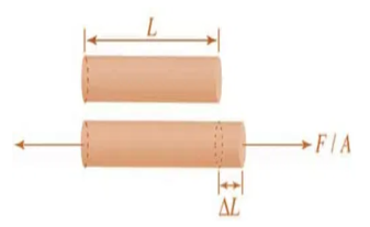
Figure. Body Subjected to tensile stress.
Bulk Modulus
When a body is subjected to mutually perpendicular direct stresses which are alike and equal, within its elastic limits, the ratio of direct stress to the corresponding volumetric strain is found to be constant. This ratio is called bulk modulus and is represented by letter “K”. Unit of Bulk modulus is Mpa.
Bulk Modulus = Direct Stress/ Volumetric Strain
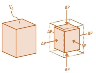
Figure. Volumetric change of body.
Rigidity Modulus
When a body is subjected to shear stress the shape of the body gets changed, the ratio of shear stress to the corresponding shear strain is called rigidity modulus or modulus of rigidity. It is denoted by the letters “G” or “C” or “N”. Unit of rigidity modulus is Mpa.
Rigidity modulus (G) = Shear Stress/ Shear Strain
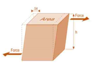
Figure. Shear Deformation of Body.
4. Poisson’s Ratio
When a body is subjected to simple tensile stress within its elastic limits then there is a change in the dimensions of the body in the direction of the load as well as in the opposite direction. When these changed dimensions are divided with their original dimensions, longitudinal strain and lateral strain are obtained.
Poisson’s ration ( μ) = Lateral Strain / Longitudinal Strain
The ratio of the lateral strain to the longitudinal strain is called Poisson’s ratio. It is represented by the symbol “µ”. Poisson’s ratio is maximum for an ideal elastic incompressible material and its value is 0.5. For most of the engineering materials, Poisson’s ratio lies between 0.25 and 0.33. It has no units.
Relationship between Elastic Constants
E = 2G(1+μ)
E = 3K(1-2μ)
E = 9KG/ (3K + G)
μ=(3K-2G) / (6K + 2G)
(A) For Brittle Metal –
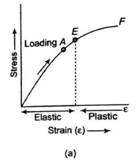
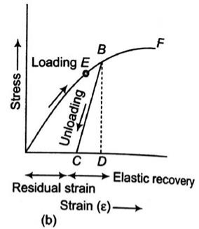
Fig No. Stress-Strain Diagram (Brittle Metal)
(B) For Ductile Metal –
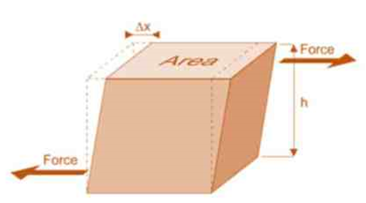
Fig No. Stress-Strain Diagram (Ductile Metal)
σT = K(εT)n
Where K is the strength coefficient
n is the strain hardening exponent
n = 0 perfectly plastic solid
n = 1 elastic solid for most metals, 0.1< n < 0.5
Key Takeaways
True stress-strain curve gives a true indication of deformation characteristics because it is based on the instantaneous dimension of the specimen.
The flow curve of many metals in the region of uniform plastic deformation can be expressed by the simple power law.
σT = K(εT)n
FOS = failure stress / working or allowable stress
Key Takeaways-
The factor of safety must be always greater than unity.
It is easier to refer to the ratio of stresses since this applies to material properties.
FOS = failure stress / working or allowable stress
A pin-connected truss composed of members AB and BC is subjected to a vertical force P = 40kN at joint B. Each member is of constant cross- sectional area: A AB = 0.004 m2 and ABC = 0.002 m2. diameter d of all pins is 20 mm, clevis thickness t is 10 mm, and the thickness t1 of the bracket is15 mm. Determine the normal stress acting in each member and the shearing and bearing stresses at joint C.
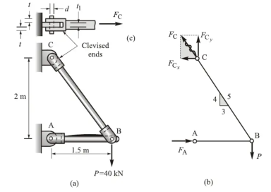
Solution
A free-body diagram of the truss is shown in Fig. b. The magnitudes of the axially directed end forces of members AB and BC which are equal to the support reactions at A and C are labeled FA and FC respectively.
For computational convenience the x and y components of the inclined forces are used rather than the forces themselves. Hence force FC is resolved into FCx and FCy as shown:
(1) Calculation of support reactions. Relative dimensions are shown by a small triangle on the member BC in fig b. From the similarity of force and relative-dimension triangles,
FCx = 3/5 FC, FCy = 4/5 FC.
It follows then that FCx = 4/3 FCy. Application of equilibrium conditions to the free body diagram in fig b leads to
 = 0: P(1.5) – FA(2) =0;
FA = ¾ P = 30kN (right directed)
 =0: FCy – P =0; FCy = P = 40kN (up directed)
 =0: -FCx + FA =0; FCx = FA = 30kN (left directed)
We thus have
FC = 5/4 P = 50kN.
Calculation of internal forces
If imaginary cutting planes are passed perpendicular to the axes of the members AB and BC, separating each into two parts, it is observed that each portion is a two-force member. Therefore, the internal forces in each member are the axial forces FA =30kN and FC = 50kN.
(3) Calculation of stresses
The normal stresses in each member are
 AB = - FA / A AB = -30 x 10 3 /0.004 = - 7.5 MPa
 BC = - FC / A BC = 50 x 10 3 /0.002 = 25 MPa
where the minus sign indicates compression. Referring to Fig. c, we see that the double shear in the pin
τC = 1/2 Fc / π d 2 /4 = 25 x 10 3 / π (0.02) 2 / 4 = 79.6 MPa
 b = Fc/ t1d = 50 x 10 3 / (0.015) (0.02) = 166.7 MPa
while the bearing stress in the clevis at joint C is given by
 b = Fc/ 2td = 50 x 10 3 / (0.015) (0.02) = 125 MPa
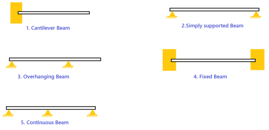
Types of Beams
The following images make all the sense what are these different types of beams.
Type of Loads that can be applied to Beams
A beam is usually horizontal, and the applied load is vertical. Following are the different types of loads.
Concentrated or Point Load: Act at a point.
Uniformly Distributed Load: Load spread along the length of the Beam.
Uniformly Varying Load: Load spread along the length of the Beam, Rate of varying loading point to point.

Sign conversion for Shear force and Bending moment


Positive Bending Moment Negative Bending Moment
Sagging Moment Hogging Moment
For a simply supported beam, If a point load is acting at the centre of the beam. Imagine a section X-X divide the beam into two portions. See the pic below.
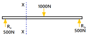
A simply supported beam is carrying a load (point load) of 1000N at its middle point. The reactions support will be equal to 500N(Ra=Rb). The section X-X make the beam into two parts.
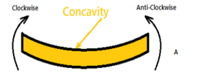
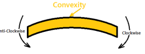
Positive Bending Moment Negative Bending Moment
The moment of all the forces, i.e., load and reaction to the left of section X-X is Clockwise
The moment of all the forces, i.e., load and reaction to the right of section X-X are Anti-Clockwise.
So this makes the beam a Sagging moment(Concavity). Here the bending moment is Positive. See (a)
If the left portion makes an anticlockwise moment and the right portion of the section makes a Clockwise moment, then it is hogging moment. Bending moment Negative.
Similarly for Shear force is positive when the left portion of the section goes upwards or the right portion of the section goes downwards.
Shear force is Negative when the left portion of the section goes downwards, or the right portion of the section goes upwards.
Structures & Classifications
Have you ever walked under a bridge or a mega structure and seen different joints between the beams and columns in the structure? Perhaps you've seen rollers and hinges and you have wondered if that is enough to support the structure. Isn't a fixed end more stable than a roller or a hinge? Well, the answer is yes. However, sometimes stability creates risk of more exposure to types of stress, such as thermal stress.
Structures are a group of members, such as beams, columns, slabs, foundations, girders, and trusses, that work as a unit to fulfil a purpose. An engineer's duty is to design structures in a professional, safe, and economical manner to fulfil the purpose for which it was designed in the first place. Structures as classified into either being statically determinate or statically indeterminate.
Statically determinate structures are structures that can be analysed using statics equations only, (i.e., equilibrium in all directions). On the other hand, statically indeterminate structures can't be analysed using statics equations only; they require other material properties, such as deformations, in order to analyse them.
When engineers conduct structural analysis, they calculate the reaction forces due to the external forces applied to the structure as well as internal forces, such as the bending moment, shear force, and normal force. Structural analysis is necessary for structural design in order for the structural engineer to choose the proper sizes and materials so the structure can economically and effectively resist the effects of the possible external loads applied to it.
Beams
About beams, if the reaction forces can be calculated using equilibrium equations alone, they are statically determinate. On the other hand, if the reaction force cannot be determined using equilibrium equations only, other methods have to be used, and the structure is said to be statically indeterminate.
If the number of unknowns exceeds the number of equations, the structure is statically indeterminate. Otherwise, it is statically determinate.
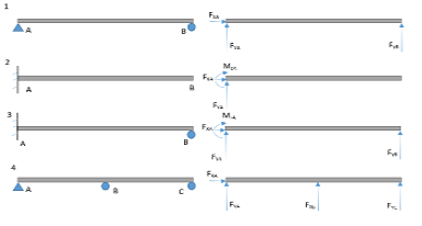
In the above figure, we have three equations for all the cases:


However, the number of unknowns are different; there are three unknowns for beams number 1 and 2, which makes them statically determinate because the number of unknowns is equal to the number of equations. On the other hand, in beams 3 and 4, there are more unknowns than there are equations. Therefore, these structures are statically indeterminate.
In three-dimensional structures, however, there will be six equations, which makes it possible to have up to six unknowns for the beam to be statically determinate. The degree of indeterminacy is equal to the number of unknowns minus the number of equations. When there are fewer reactions than there are equations, however, this makes the beam unstable.
Shear Force
A shear force that tends to move the left of the section upward or the right side of the section downward will be regarded as positive. Similarly, a shear force that has the tendency to move the left side of the section downward or the right side upward will be considered a negative shear force (see Figure 4.2c and Figure 4.2d).
Bending Moment
A bending moment is considered positive if it tends to cause concavity upward (sagging). If the bending moment tends to cause concavity downward (hogging), it will be considered a negative bending moment (see figure 4.2 e and figure 4.2 f).

Fig. Sign conventions for axial force, shearing force, and bending moment.
Shear and bending moment diagrams are analytical tools used in conjunction with structural analysis to help perform structural design by determining the value of shear force and bending moment at a given point of a structural element such as a beam.
These diagrams can be used to easily determine the type, size, and material of a member in a structure so that a given set of loads can be supported without structural failure.
Another application of shear and moment diagrams is that the deflection of a beam can be easily determined using either the moment area method or the conjugate beam method.
The algebraic sum of the vertical forces at any section of a beam to the right or left of the section is known as shear force.
It is briefly written as S.F. The algebraic sum of the moments of all the forces acting to the right or left of the section is known as bending moment.
It is written as B.M. In this chapter, the shear force and bending moment diagrams for different types of beams (i.e., cantilevers, simply supported, fixed, overhanging etc.) for different types of loads (i.e., point load, uniformly distributed loads, varying loads etc.) acing on the beams, will be considered.
A) Shear Force –
A shear force (SF) is defined as the algebraic sum of all the vertical forces, either to the left or to the right- hand side of the section.
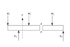
Shear Force
B) Bending Moment –
A bending moment (BM) is defined as the algebraic sum of the moments of all the forces either to the left or to the right of a section.
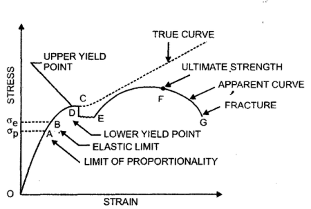
Fig. Bending Moment
Sign Convention of SF and BM –
A) For Shear force –
To the right side of a section, external force acting in upward direction is treated as negative (remember this convention as RUN —» Right side of a section Upward force is Negative).
It is automatic that a downward force acting to the right side of a section be treated as positive.
The signs become just reversed when we consider left side of section. A shear force which tends to rotate the beam in clockwise direction is positive and vice versa.
B) For Bending Moment –
The internal resistive moment at the section that would make the beam to sag (means to sink down, droop) is treated to be positive.
A sagged beam will bend such that it exhibits concave curvature at top and convex curvature at bottom.
The internal resistive moment that would hog the beam is treated as negative.
A hogged beam will show convex curvature at top and concave curvature at bottom.

Table- Sign conventions for External loads, Shear force and bending moment
General Guidelines on Construction of SFD and BMD –
Before we go on to solving problems, several standard procedures (or practices) in relation with construction of shear force and bending moment diagrams need to be noted.
1) The load, shear and bending moment diagrams should be constructed one below the other, in that order, all with the same horizontal scale.
2) The dimension on the beam need not be scaled but should be relative and proportionate (a 3 m span length should not look more than 5 m length!).
3) Ordinates (i.e., BM and SF values) need not be plotted to scale but should be relative. Curvature may need to be exaggerated for clarity.
4) Principal ordinates (BM and SF values at salient points) should be labeled on both SFD and BMD.
5) A clear distinction must be made on all straight lines as to whether the line is horizontal or has a positive or negative slope.
6) The entire diagram may be shaded or hatched for clarity, if desired.
Short tricks of SFD and BMD:
Sr.No | Loading | Shear force diagram | Bending Moment diagram |
1 | No Load between two section | Horizontal line | Inclined line |
2 | U.D.L between two sections | Inclined line | Parabolic curve |
3 | U.V.L between two section | Parabolic curve | Cubic curve |
4 | Point load at a point | Rise or drop at that point | - |
5 | Couple at a point | - | Rise or drop at that point |
6 | Internal hinges | No effect in S.F.D | B.M.D is zero |
Key Takeaways
A shear force (SF) is defined as the algebraic sum of all the vertical forces, either to the left or to the right hand side of the section.
A bending moment (BM) is defined as the algebraic sum of the moments of all the forces either to the left or to the right of a section.
To the right side of a section, external force acting in upward direction is treated as negative (remember this convention as RUN —» Right side of a section Upward force is Negative).
The internal resistive moment at the section that would make the beam to sag (means to sink down, droop) is treated to be positive.
For the derivation of the relations among w, V, and M, consider a simply supported beam subjected to a uniformly distributed load throughout its length, as shown in Figure 4.3. Let the shear force and bending moment at a section located at a distance of x from the left support be V and M, respectively, and at a section x + dx be V + dV and M + dM, respectively. The total load acting through the center of the infinitesimal length is wdx.
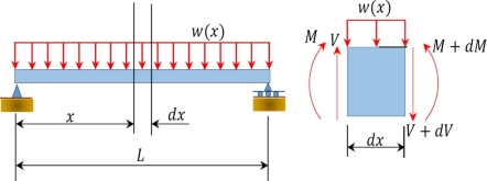
Fig. Simply supported beam.
To compute the bending moment at section x + dx, use the following:
M x + dx = M + Vdx – wdx. dx/2
= M + Vdx (neglecting the small second order term wdx 2 / 2)
M + dM = M + V dx -----------------------------------------------------------Eq(4.1)
Eq(4.1 ) implies that the first derivative of the bending moment with respect to the distance is equal to the shearing force. The equation also suggests that the slope of the moment diagram at a particular point is equal to the shear force at that same point. Equation (4.1) suggests the following expression:
 -------------------------------------------- Eq(4.2)
Equation 4.2 states that the change in moment equals the area under the shear diagram. Similarly, the shearing force at section x + dx is as follows:
Vx+dx = V – wdx
V + dV = V – wdx
Or
dV/dx = -w(x) --------------------------------------------------------- Eq(4.3)
Equation (4.3) implies that the first derivative of the shearing force with respect to the distance is equal to the intensity of the distributed load. Equation (4.3) suggests the following expression:
 ------------------------------------- Eq(4.4)
Eq(4.4) states that the change in the shear force is equal to the area under the load diagram. Equation (4.1) and (4.3) suggest the following:
d 2 M / dx2 = -w(x) ------------------------------------------------Eq(4.5)
Equation (4.5) implies that the second derivative of the bending moment with respect to the distance is equal to the intensity of the distributed load.
Draw the shearing force and bending moment diagrams for the cantilever beam subjected to a uniformly distributed load in its entire length, as shown in figure.

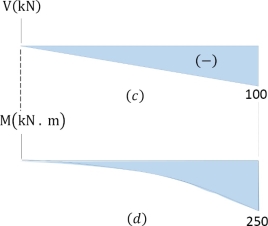
Fig. Cantilever beam.
Solution
Support reactions. First, compute the reactions at the support. Since the support at B is fixed, there will possibly be three reactions at that support, namely By, Bx, and MB, as shown in the free-body diagram in Figure 4.4 b. Applying the conditions of equilibrium suggests the following:
 =0 (20kN/m) (5m)(2.5m) -M =0
M = 250 kN.m
 =0 -(20kN/m) (5m) + By =0
By =100kN
 =0 Bx =0
Shearing force (SF).
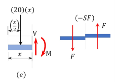
Shearing force function. Let x be the distance of an arbitrary section from the free end of the cantilever beam, as shown in Figure 4.5 b. The shearing force of all the forces acting on the segment of the beam to the left of the section, as shown in Figure 4.5 e , is determined as follows:
0<x<5
V = -20 x
When x=0, V=0
When x=2.5 m, V = -50kN
When x=5m, V = -100kN.
The obtained expression is valid for the entire beam. The negative sign indicates a negative shearing force, which was established from the sign convention for a shearing force. The expression also shows that the shearing force varies linearly with the length of the beam.
Shearing force diagram. Note that because the expression for the shearing force is linear, its diagram will consist of straight lines. The shearing force at x = 0 m and x = 5 m were determined and used for plotting the shearing force diagram, as shown in Figure 4.5 c . As shown in the diagram, the shearing force varies from zero at the free end of the beam to 100 kN at the fixed end. The computed vertical reaction of By at the support can be regarded as a check for the accuracy of the analysis and diagram.
Bending moment (BM).
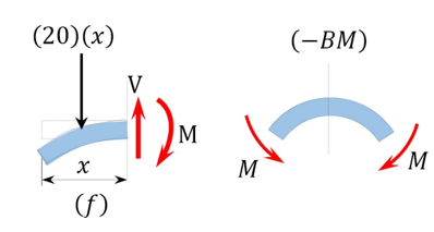
Bending moment expression. The expression for the bending moment at a section of a distance x from the free end of the cantilever beam is as follows:
0 < x<5 m
M = -20 x 2 /2
When x=0, M=0
When x=2.5m, M =-62.5 k N.m
When x=5m, M = -250 kN.m
The negative sign indicates a negative moment, which was established from the sign convention for moment. As seen in Figure 4.5f, the moment due to the distributed load tends to cause the segment of the beam on the left side of the section to exhibit an upward concavity, and that corresponds to a negative bending moment, according to the sign convention for bending moment.
Bending moment diagram. Since the function for the bending moment is parabolic, the bending moment diagram is a curve. In addition to the two principal values of bending moment at x = 0 m and at x = 5 m, the moments at other intermediate points should be determined to correctly draw the bending moment diagram. The bending moment diagram of the beam is shown in Figure.
References:
1. Basic Mechanical Engineering, G Shanmugam, S Ravindran, McGraw Hill
2. Basic Mechanical Engineering, M P Poonia and S C Sharma, Khanna Publishers
3. Mechatronics: Principles, Concepts and Applications, Nitaigour Mahalik, McGraw Hill
4. Mechatronics, As per AICTE: Integrated Mechanical Electronic Systems, K.P. Ramachandran, G.K. Vijayaraghavan, M.S. Balasundaram, Wiley India
5. Mechanical Measurements & Control, Dr. D. S. Kumar. Metropolitan Book Company