Unit - 3
Multiple Access
Multiple Access Protocols in Computer Networks
1. Random Access Protocol: In this, all stations have same superiority that is no station has more priority than another station. Any station can send data depending on medium’s state (idle or busy). It has two features:
- There is no fixed time for sending data
- There is no fixed sequence of stations sending data
The Random-access protocols are further subdivided as:
(a) ALOHA – It was designed for wireless LAN but is also applicable for shared medium. In this, multiple stations can transmit data at the same time and can hence lead to collision and data being garbled.
- PureAloha:
When a station sends data it waits for an acknowledgement. If the acknowledgement doesn’t come within the allotted time. Then the station waits for a random amount of time called back-off time (Tb) and re-sends the data. Since different stations wait for different amount of time, the probability of further collision decreases. - Vulnerable Time = 2* Frame transmission time
- Throughput = G exp{-2*G}
Maximum throughput = 0.184 for G=0.5
- Slotted Aloha:
- It is similar to pure aloha, except that we divide time into slots and sending of data is allowed only at the beginning of these slots. If a station misses out the allowed time, it must wait for the next slot. This reduces the probability of collision.
- Vulnerable Time = Frame transmission time
- Throughput = G exp{-*G}
Maximum throughput = 0.368 for G=1
(b) CSMA – Carrier Sense Multiple Access ensures fewer collisions as the station is required to first sense the medium (for idle or busy) before transmitting data. If it is idle then it sends data, otherwise it waits till the channel becomes idle. However there is still chance of collision in CSMA due to propagation delay. For example, if station A wants to send data, it will first sense the medium. If it finds the channel idle, it will start sending data. However, by the time the first bit of data is transmitted (delayed due to propagation delay) from station A, if station B requests to send data and senses the medium it will also find it idle and will also send data. This will result in collision of data from station A and B.
CSMA access modes-
- 1-persistent: The node senses the channel, if idle it sends the data, otherwise it continuously keeps on checking the medium for being idle and transmits unconditionally (with 1 probability) as soon as the channel gets idle.
- Non-Persistent: The node senses the channel, if idle it sends the data, otherwise it checks the medium after a random amount of time (not continuously) and transmits when found idle.
- P-persistent: The node senses the medium, if idle it sends the data with p probability. If the data is not transmitted ((1-p) probability) then it waits for some time and checks the medium again, now if it is found idle then it send with p probability. This repeat continues until the frame is sent. It is used in Wifi and packet radio systems.
- O-persistent: Superiority of nodes is decided beforehand and transmission occurs in that order. If the medium is idle, node waits for its time slot to send data.
(c) CSMA/CD – Carrier sense multiple access with collision detection. Stations can terminate transmission of data if collision is detected. For more details refer – Efficiency of CSMA/CD
(d) CSMA/CA – Carrier sense multiple access with collision avoidance. The process of collisions detection involves sender receiving acknowledgement signals. If there is just one signal (its own) then the data is successfully sent but if there are two signals (its own and the one with which it has collided) then it means a collision has occurred. To distinguish between these two cases, collision must have a lot of impact on received signal. However, it is not so in wired networks, so CSMA/CA is used in this case.
CSMA/CA avoids collision by:
- Inter frame space – Station waits for medium to become idle and if found idle it does not immediately send data (to avoid collision due to propagation delay) rather it waits for a period of time called Inter frame space or IFS. After this time it again checks the medium for being idle. The IFS duration depends on the priority of station.
- Contention Window – It is the amount of time divided into slots. If the sender is ready to send data, it chooses a random number of slots as wait time which doubles every time medium is not found idle. If the medium is found busy it does not restart the entire process, rather it restarts the timer when the channel is found idle again.
- Acknowledgement – The sender re-transmits the data if acknowledgement is not received before time-out.
2.ControlledAccess:
In this, the data is sent by that station which is approved by all other stations. For further details refer – Controlled Access Protocols
3.Channelization:
In this, the available bandwidth of the link is shared in time, frequency and code to multiple stations to access channel simultaneously.
- Frequency Division Multiple Access (FDMA) – The available bandwidth is divided into equal bands so that each station can be allocated its own band. Guard bands are also added so that no to bands overlap to avoid crosstalk and noise.
- Time Division Multiple Access (TDMA) – In this, the bandwidth is shared between multiple stations. To avoid collision time is divided into slots and stations are allotted these slots to transmit data. However there is a overhead of synchronization as each station needs to know its time slot. This is resolved by adding synchronization bits to each slot. Another issue with TDMA is propagation delay which is resolved by addition of guard bands.
For more details refer – Circuit Switching - Code Division Multiple Access (CDMA) – One channel carries all transmissions simultaneously. There is neither division of bandwidth nor division of time. For example, if there are many people in a room all speaking at the same time, then also perfect reception of data is possible if only two person speak the same language. Similarly data from different stations can be transmitted simultaneously in different code languages.
Key takeaway
Approach | SDMA | TDMA | FDMA | CDMA |
Idea | Segment space into cells/sectors | Segment sending time into disjoint time-slots, demand driven or fixed patters | Segment the frequency band into disjoint sub-bands | Spread the spectrum using orthogonal codes
|
Terminals | Only one terminal can be active in one cell/one sector | All terminals are active for short periods of time on the same frequency | Every terminal has its own frequency. Uninterrupted | All terminals can be active at the same place at the same moment uninterrupted. |
Signal separation | Cell structure, directed antennas | Synchronization in the time domain | Filtering in the frequency domain | Code plus special receivers |
Advantages | Very simple, increases capacity per km2 | Established, fully digital, flexible | Simple, established robust | Flexible, less frequency planning needed, soft handover |
Disadvantages | Inflexible, antennas typically fixed | Guard space needed (multipath propagation), synchronization difficult | Inflexible, frequencies are a scarce resource | Complex receivers, needs more complicated power control for senders |
Comment | Only in combination with TDMA, FDMA or CDMA useful | Standard in fixed networks, together with FDMA/SDMA used in many mobile networks | Typically combined with TDMA (frequency hopping patterns) and SDMA (frequency reuse) | Still faces some problems, higher complexity, lowered expectations: will be integrated with TDMA/FDMA |
CDMA means communication with different codes. CDMA differs from FDMA because only one channel occupies the entire bandwidth of the link. It differs from TDMA because all stations can send data simultaneously and there is no timesharing.
Let us assume we have four stations 1, 2, 3, and 4 connected to the same channel. The data from station 1 are d1, from station 2 are d2, and so on. The code assigned to first station is c1, and second is c2, and so on. We assume that the assigned codes have two properties.
1. If we multiply each code by another, we get 0.
2. If we multiply each code by itself, we get 4 that is the number of stations.
With this in picture the four stations can send data using the same common channel, as shown in the following figure.
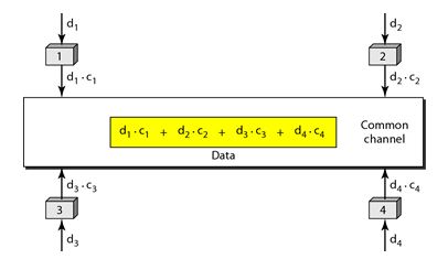
Fig: Four station sending data using common channel
Station 1 multiplies its data by its code to get d1.c1. Station 2 multiplies its data by its code to get d2.c2. And so on. The data that go on the channel are the sum of all these terms, as shown in the box.
Any station that wants to receive data from one of the other three multiplies the data on the channel by the code of the sender.
For example, suppose stations 1 and 2 are talking to each other. Station 2 wants to hear what station 1 is saying. It multiplies the data on the channel by c1 the code of station1.
Because (c1.c1) is 4, but (c2. c1), (c3. c1), and (c4 .c1) are all 0s, station 2 divides the result by 4 to get the data from station1.
Data =(d1.c1+d2.c2+d3.c3+d4.c4).c1
= c1. d1. c1+ c1. d2. c2+ c1. d3. c3+ c1. d4. c4= 4d1
Carrier Sense Multiple Access with Collision Detection (CSMA/CD) –
In this method, a station monitors the medium after it sends a frame to see if the transmission was successful. If successful, the station is finished, if not, the frame is sent again.

Fig: Frame Transmission
In the diagram, A starts to send the first bit of its frame at t1 and since C sees the channel idle at t2, starts sending its frame at t2. C detects A’s frame at t3 and aborts transmission. A detects C’s frame at t4 and aborts its transmission. Transmission time for C’s frame is therefore t3-t2 and for A’s frame is t4-t1.
Therefore, frame transmission time (Tfr) should be at least twice the maximum propagation time (Tp). This can be deduced when the two stations involved in collision are maximum distance apart.
Process–
The entire process of collision detection is explained as:

Fig: Process of collision detection
Throughput and Efficiency – The throughput of CSMA/CD is much greater than pure or slotted ALOHA.
- For 1-persistent method throughput is 50% when G=1.
- For non-persistent method throughput can go upto 90%.
Carrier Sense Multiple Access with Collision Avoidance (CSMA/CA) –
In CSMA/CA is that the station should be able to receive while transmitting to detect a collision from different stations.
In wired networks, if a collision has occurred then the energy of received signal almost doubles and the station can sense the possibility of collision.
In wireless networks, most of the energy is used for transmission and the energy of received signal increases by only 5-10% if there is collision.
It cannot be used by the station to sense collision. Therefore CSMA/CA has been specially designed for wireless networks.
These are three types of strategies:
- InterFrame Space (IFS) – When a station finds the channel busy, it waits for a period of time called IFS time. IFS can also be used to define the priority of a station or a frame. Higher the IFS lower is the priority.
- Contention Window – It is the amount of time divided into slots.A station which is ready to send frames chooses random number of slots as wait time.
- Acknowledgements – The positive acknowledgements and time-out timer can help guarantee a successful transmission of the frame.
Process–
The entire process for collision avoidance can be explained as follows:
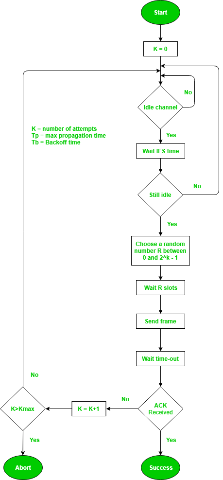
Fig: Process of collision avoidance
In controlled access, the stations seek information from one another to find which station has the right to send. Only one node can send at a time, to avoid collision of messages on shared medium.
The three controlled-access methods are:
- Reservation
- Polling
- Token Passing
Reservation
- In the reservation method, a station needs to make a reservation before sending data.
- The time-line has two kinds of periods:
- Reservation interval of fixed time length
- Data transmission period of variable frames.
- If there are M stations, the reservation interval is divided into M slots, and each station has one slot.
- Suppose if station 1 has a frame to send, it transmits 1 bit during the slot 1. No other station can transmit during this slot.
- In general, i th station may announce that it has a frame to send by inserting a 1 bit into i th slot. After all N slots have been checked, each station knows which stations wish to transmit.
- The stations which have reserved their slots transfer their frames in that order.
- After data transmission period, next reservation interval begins.
- Since everyone agrees on who goes next, there will never be any collisions.
The following figure shows a situation with five stations and a five- slot reservation frame.
In the first interval, only stations 1, 3, and 4 have made reservations. In the second interval, only station 1 has made a reservation.

Fig: Stations with slot reservations
Polling
- Polling process similar to roll-call is performed in class. Just like the teacher, a controller sends a message to each node in turn.
- In this, one acts as a primary station(controller) and the others are secondary stations. All data exchanges must be made through the controller.
- The message sent by the controller contains the address of the node being selected for granting access.
- Although all nodes receive the message only the addressed one responds to it and sends data. If there is no data, usually a “poll reject” (NAK) message is sent back.
- Problems include high overhead of the polling messages and high dependence on the reliability of the controller.
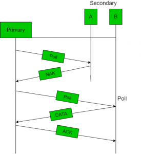
Fig: Polling
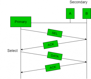
Fig: Polling Acknowledge
Efficiency
Let Tpoll be the time for polling and Tt be the time required for transmission of data. Then,
Efficiency = Tt / (T t + T poll)
Token Passing
- In token passing scheme, the stations are connected logically to each other in form of ring and access of stations is governed by tokens.
- A token is a special bit pattern or a small message, which circulate from one station to the next in some predefined order.
- In Token ring, token is passed from one station to another adjacent station in the ring whereas in Token bus, each station
uses the bus to send the token to the next station in some predefined order. - In both cases, token represents permission to send. If a station has a frame queued for transmission when it receives the token, it can send that frame before it passes the token to the next station. If it has no queued frame, it passes the token simply.
- After sending a frame, each station must wait for all N stations (including itself) to send the token to their neighbours and the other N – 1 stations to send a frame, if they have one.
- Problems like duplication of token or token is lost or insertion of new station, removal of a station, which need be tackled for correct and reliable operation of this scheme.

Fig: Token
Performance
Performance of token ring is concluded by 2 parameters: -
- Delay, which is a measure of time between when the packet is ready and when it is delivered. So, the average time (delay) required to send a token to the next station = a/N.
- Throughput, which is a measure of the successful traffic.
Throughput S = 1/(1+a/N) for a<1 and
S= 1/ {a(1+1/N)} for a>1
Where N = number of stations
a = Tp / Tt; Tp = Propagation delay, Tt = Transmission delay.
Key takeaway
In polling
- The message sent by the controller contains the address of the node being selected for granting access.
- Although all nodes receive the message only the addressed one responds to it and sends data. If there is no data, usually a “poll reject” (NAK) message is sent back.
- Problems include high overhead of the polling messages and high dependence on the reliability of the controller.
Institute of Electrical and Electronics professional organization for the advancement of technology related to electricity. Formed in 1963 by the merger of IRE (Institute of Radio Engineers) and AIEE (American Institute of Electrical Engineering) IEEE is one of the leading standards-making organizations in the world. IEEE performs its standards making and maintaining functions through the IEEE Standards Association (IEEE-SA).
IEEE Standards
The Institute of Electrical and Electronics Engineers Standards Association (IEEE-SA) is a leading developer of global industry standards in a broad-range of industries, including:
- Power and Energy
- Biomedical and Healthcare
- Information Technology
- Telecommunications
- Transportation
- Nanotechnology
- Information Assurance
Development of IEEE Standards
The IEEE standards development process can be broken down into seven basic steps, as follows:
- Securing Sponsorship
- Requesting Project Authorization
- Assembling a Working Group
- Drafting the Standards
- Balloting
- Review Committee
IEEE 802
IEEE 802 refers to a family of IEEE standards dealing with local area networks and metropolitan area networks.
The services and protocols specified in IEEE 802 map to the lower two layers (Data Link and Physical) of the seven-layer OSI networking reference model. In fact, IEEE 802 splits the OSI Data Link Layer into two sub-layers named Logical Link Control (LLC) and Media Access Control (MAC), so that the layers can be listed like this:
- Data link layer
- LLC Sublayer
- MAC Sublayer
Physical layer
- IEEE 802.1-Bridging (networking) and Network Management
- IEEE 802.2-Logical link control
- IEEE 802.3-Ethernet
- IEEE 802.4-Token bus
- IEEE 802.5-Defines the MAC layer for a Token Ring
- IEEE 802.6-Metropolitan Area Networks
- IEEE 802.7-Broadband LAN using Coaxial Cabled
- IEEE 802.8-Fiber Optic TAG
- IEEE 802.9-Integrated Services LAN
- IEEE 802.10-Interoperable LAN Security
- IEEE 802.11 a/b/g/n-Wireless LAN (WLAN) & Mesh (Wi-Fi certification)
- IEEE 802.12-demand priority
- IEEE 802.13-Used for 100Base-X Ethernet
- IEEE 802.14-Cable Modem
- IEEE 802.15-Wireless PAN
- IEEE802.15.1-Bluetoothcertification
- IEEE 802.15.2-IEEE 802.15 and IEEE 802.11 coexistence
- IEEE 802.15.3-High-Rate WPAN certification
- IEEE 802.15.4-Low-rate WPAN certification
- IEEE 802.15.5-Mesh networking for WPAN
- IEEE 802.16-Broadband Wireless Access (WiMAX certification)
Ethernet is very popular physical layer LAN technology which is in use today. It defines that how many conductors that are required for a connection, the performance thresholds that can be expected, and most importantly provides the framework for data transmission. A standard Ethernet network can transmit the data at a rate up to 10 Megabits per second (10 Mbps). Other LAN types include Token Ring, Fast Ethernet, Gigabit Ethernet, 10 Gigabit Ethernet, Fibre Distributed Data Interface (FDDI), Asynchronous Transfer Mode (ATM) and Local Talk.
Ethernet is popular because it strikes a very good balance between speed, cost and ease of installation. These benefits, combined with wide acceptability in the computer marketplace and the ability to support virtually all the popular network protocols, which make Ethernet an ideal networking technology for most of the computer users today.
The Institute for Electrical and Electronic Engineers developed an Ethernet standard that is known as IEEE Standard 802.3. This standard defines the rules for configuring an Ethernet network and then also specifies how the elements in an Ethernet network interact with one another and work. By adhering to the IEEE standard, network equipment and network protocols can communicate very efficiently.
Fast Ethernet
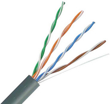
Fig: Twisted pair cable
The fast Ethernet is a type of Ethernet network that can be transfer the data at a speed of 100 Mbps using a twisted-pair cable or a fibre-optic cable. The older 10 Mbps Ethernet is still used, but such kind of networks does not provide necessary bandwidth for some network-based video applications.
Fast Ethernet is based on CSMA/CD Media Access Control (MAC) protocol, and use10BaseT cabling. Data can move from 10 Mbps to 100 Mbps without any protocol translation or changes done to the application and networking software.
Gigabit Ethernet
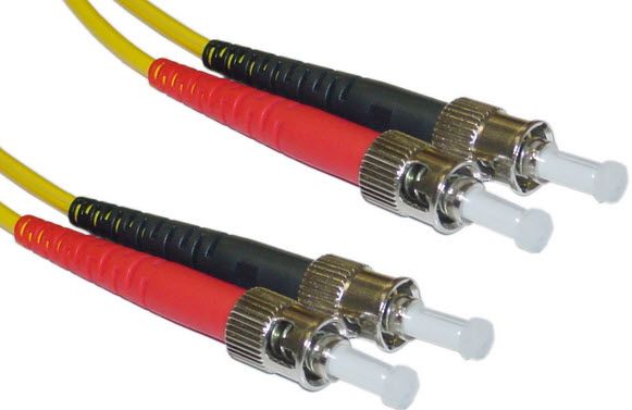
Fig: Optic fibre cable
The Gigabit Ethernet is a type of Ethernet network that is capable of transferring data at a speed of 1000 Mbps based on a twisted-pair or fibre optic cable, and it is very commonly used. The type of twisted-pair cables that support Gigabit Ethernet is the Cat 5e cable, where all the four pairs of twisted wires of the cable are used to achieve the very high data transfer rates. The 10 Gigabit Ethernet is a very latest generation Ethernet capable of transferring data at a speed of 10 GBPS using twisted-pair or fibre optic cable.
IEEE 802.11 is a set of standards carrying out wireless local area network (WLAN) computer communication in the 2.4, 3.6 and 5 GHz frequency bands. They are created and maintained by the IEEE LAN/MAN Standards Committee (IEEE 802)
802.11a — an extension to 802.11 that applies to wireless LANs and provides up to 54-Mbps in the 5GHz band. 802.11a uses an orthogonal frequency division multiplexing encoding scheme rather than FHSS or DSSS.
802.11b — an extension to 802.11 that applies to wireless LANS and provides 11 Mbps transmission in the 2.4 GHz band. 802.11b uses only DSSS. 802.11b was a 1999 ratification to the original 802.11 standard, allowing wireless functionality comparable to Ethernet.
802.11e — a wireless draft standard that defines the Quality of Service support for LANs, and is an enhancement to the 802.11a and 802.11b wireless LAN (WLAN) specifications. 802.11e adds QoS features and multimedia support to the existing IEEE 802.11b and IEEE 802.11a wireless standards, while maintaining full backward compatibility with these standards.
802.11g — applies to wireless LANs and is used for transmission over short distances at up to 54-Mbps in the 2.4 GHz bands.
802.11n — 802.11n builds upon previous 802.11 standards by adding multiple-input multiple-output. The additional transmitter and receiver antennas allow for increased data throughput through spatial multiplexing and increased range by exploiting the spatial diversity through coding schemes like Alamouti coding. The real speed would be 100 Mbit/s (even 250 Mbit/s in PHY level), and so up to 4-5 times faster than 802.11g.
The growing need for higher data rates has forced researchers and technologists alike to develop better transmission methods with greater efficiency. This has also led to the growth of broadband data communications like never before seen. And the need does not appear to be slowing down anytime soon. It would not be an unrealistic assumption or prediction to propose that in the future there will continue to be a need for higher data rates so long as communications remains a viable part of humanity [7]. It is important to be clear about what is meant by broadband communications.
Typically, “broadband” means the capability to deliver significant bandwidth to each user, much higher than narrowband voiceband modems. With International Telecommunications Union (ITU) terminology, the term “broadband” means transmission rates greater than 1.5Mb/s. Broadband Internet access has become a prevalent industry reaching 100 million homes and some 5 million businesses just in the United States. There are generally four major technologies for broadband Internet access. They are: DSL, cable, wireless, and optical fiber communications. DSL and cable occupy most of the market now but with the expansion of wireless access, specifically cellular technology and WiMAX, it is expected that broadband wireless access (BWA) systems will become a competitive technology. If BWA systems are to compete with DSL and Cable, their market growth will be significant for several reasons.
First, BWA systems are capable of delivering significantly higher data rates than DSL or cable. DSL can deliver up to 6Mb/s at distances up to 18,000 feet, hence the customers’ needs to be close to the telephone company’s central office. Not everyone in North America has DSL or cable access, not to mention the global implications of access. The IEEE 802.16 Working Group was formed in August 1998 with a primary purpose of delivering network access to enterprise and residence customers via a secure broadband wireless facility. The first standard was published in early April 2002 and was known as IEEE 802.16-2001. There have been several iterations since that will be discussed later in this chapter.
The standard is quite precise in its description of the intended capability. It specifies that network access will be achieved by means of external antennas connected to central base stations, offering a connectivity alternative to wired broadband options. Since wireless solutions can provide services to a large geographic without the need to spend inordinate quantities of capital expense and operating expense in the process, it may turn out to be a less expensive service delivery option than its wired predecessors and may become the solution for broadband delivery in areas that are challenged by distance, population density, or topologic difficulties.
Worldwide Interoperability for Microwave Access (WiMAX) is a wireless communication system that allows computer and workstations to connect to high-speed data networks (such as the Internet) using radio waves as the transmission medium with data transmission rates that can exceed 75 Mbps for each radio channel. WiMAX will be used for both fixed and mobile broadband wireless access. It is a system that is primarily used as a wireless metropolitan area network (WMAN). WMANs can provide broadband data communication access throughout an urban or city geographic area.
WMANs are used throughout the world and their applications include consumer broadband wireless Internet services, interconnecting lines, and transport of digital television services. The IEEE 802.16 system was designed for fixed location Nomadic service. Nomadic service is defined as providing communication services to more than one location for the subscriber. However, nomadic service typically requires the transportable communication device to be fixed in location during the usage of communication service.
IEEE 802.16 Architecture
The IEEE 802.16 standard provides for two main distinct uses of this technology, point to point (PTP) and point to multipoint (PMP), as shown in Figure 13. PTP connections may be independent from all other systems or networks. A PMP system allows a radio system to provide services to multiple users. WiMAX systems consist of:
- Subscriber stations (SS) – receive and convert radio signals into user information.
- Base stations (BS) – this is the cell site. Base stations convert signals from SSs into a form that can be transferred into the wireless network and conversely.
- Interconnecting switches and transmission lines – transfer signals between BS and other systems (such as PSTN or the Internet)
- Databases – similar to cellular network structure, these are collections of data that is interrelated and stored in memory. These databases usually contain subscriber information, equipment configuration, feature lists and security codes.
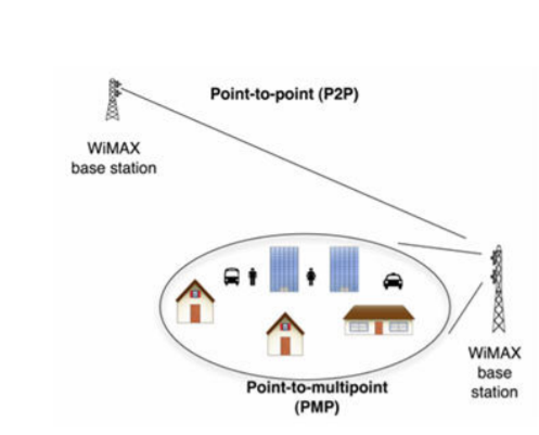
Fig: Description of PTP and PMP
The original 802.16 industry specification was for a line of sight system that would operate in the 10GHz to 66 GHz radio spectrum. Not long after, there was a growing need to operate in the lower ranges, namely in the 2GHz to 11GHz bands, because they are less susceptible to physical obstacles. The 802.16a specification was developed to address operation in the new spectrum ranges. Recently, several different revisions have been developed to address an operating range between 2GHz and 66GHz that allow for mobility and higher data rates. More importantly, the new revisions allow for operation in both line-of-sight (LOS) and non-line-of-sight (NLOS) environments as shown in Figure below.

Figure: LOS vs. NLOS
Data Link Layer:
802.16 MAC Layers and Sublayers Media Access Control (MAC) controls access to whatever physical transmission medium is being used by the device that wishes to transmit. The functionality of the MAC layer is usually “hard-coded” into the device and always includes a unique address (the MAC address) that identifies the machine that houses the network adapter. The 802.16 MAC protocol was designed with a number of required characteristics in mind. First, it was created to handle the demands of PTMP broadband wireless applications. Within that definition, it also was designed to provide very high, full-duplex (uplink and downlink) bandwidth, with that bandwidth being capable of being parceled out across a collection of channels with scores of users in each channel.
Additionally, users place varying demands on the channels they are allocated; this translates into a requirement to support traditional voice and data services as well as packet-based Voice over Internet Protocol (VoIP) and other Internet Protocol (IP) data services. The MAC, then, must be able to handle the demands of both constant bit rate (CBR) and bursty traffic and must support variable QoS as demanded by the user community.
The MAC layer consists of three sublayers – convergence sublayer, common part sublayer, and security sublayer as shown in Figure below. The MAC includes a convergence sublayer to better handle the higher-layer protocols placed above the MAC. The central part of the MAC is the common part sublayer. It handles channel access, connection establishment and maintenance, and QoS. The third sublayer is the security sublayer, providing authentication, secure key exchange, and secure data exchange. The security sublayer is out of the scope of this thesis. The convergence sublayer is not a physical, but rather a logical interface since it is a separate part of the MAC.
The common part sublayer is the central part of the IEEE 802.16 MAC. It defines the multiple-access mechanism. In the downlink for the 802.16d, the base station is the only transmitter that is operating. Therefore, it does not have to coordinate its transmissions with other stations. The base station broadcasts to all stations. Stations check the address in the received messages and retain only those addressed to them. In the uplink direction, the user stations share the channel.
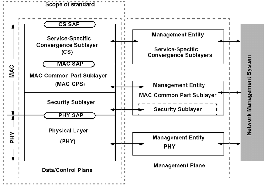
Figure: Protocol Layering of 802.16
IEEE 802.16 Physical Layer
Generally, physical layers have two sublayers: a transmission convergence sublayer and a Physical Medium Dependent (PMD) sublayer. Each PMD sublayer may have its own definition of a particular transmission convergence sublayer. In addition, a physical layer may be accompanied by a physical layer management entity. The IEEE 802 standards do not specify the exact functions of the management entity; those functions are left up to the vendors. This management entity generally is responsible for such functions as gathering of layer-dependent status and interaction with general system management. IEEE 802.16 defines several physical layers, for business and other purposes.
The main benefit of this is that it allows vendors the ability to implement whichever one they want. These vendors are then able to experiment and conduct research to see which particular layers operate at an optimal level under certain criteria. As was discussed, there are two primary operating ranges for 802.16, the 2 to 11 GHz range and the 10 to 66 GHz range. Both operate quite differently with different purposes. IEEE 802.16 and its corresponding WiMAX technology offer two completely different implementation options. They are: line of sight (LOS) and non-line of sight (NLOS). These options actually lend themselves to a variety of different uses for this technology. The reason lies within the physics behind the options themselves.
The first is a line of sight (LOS) option. These systems will operate in the 10 to 66 GHz frequency range. The idea is that in this scenario a fixed antenna, typically a small dish, is oriented so that it can “see” the antenna mounted on a remote WiMAX tower. This is a very reliable service option because it relies on an uninterrupted microwave connection between two antennas. Since it operates in the higher ranges of the frequency band, it has greater available bandwidth but shorter range. Notwithstanding the facts that since these are shorter distances between end-points there is a chance for reduced interference. LOS systems in general can operate at distances up to about five miles, and this provides a very rough service footprint of about 75 square miles. With high-end antennas, it is quite possible to transmit as far as 30 miles to one of the high-end routers on the market today. However, increased distances generally mean decreased bandwidth. The characteristics of outdoor wireless channels can be quite different.
In wireless communications over 10GHz, the multipath components will be absorbed rather than reflected. The energy on these LOS components that end up reaching the receiver are quite small. This is why they must be within LOS and not travel very large distances because the energy lessens with range and interference. The physical layer for operation between 10 GHz and 66 GHz must allow for flexible spectrum usage and support both time division duplexing (TDD) and frequency division duplexing (FDD).
The burst transmission format of the PHY is framed so that it supports adaptive burst profiling in which transmission parameters, including the modulation and coding schemes, can be adjusted to support both the physical and communications requirements of each subscriber station (SS) on a frame-by-frame basis. It also uses adaptive modulation which means that systems communicate using multiple burst profiles. There is a further distinction within the physical layer: the uplink physical layer and the downlink physical layer.
These have completely different functionality obviously, and therefore different parameters. The uplink physical layer is based on a combination of time division multiple access (TDMA) and demand-assigned multiple access (DAMA). The TDMA part is divided into a number of time slots. The downlink channel is time division multiplexed (TDM), with the information for each subscriber station multiplexed onto a single stream of data and received by all subscriber station within the same sector. Non line of sight 802.16 systems operate in a much lower frequency range (2 to 11 GHz) and are therefore less susceptible to physical obstacles. These systems rely on a signal-encoding scheme already mentioned in this chapter known as OFDM. Ultimately, WiMAX technology will facilitate the deployment of what has become to be known as Global Area Network (GAN). GAN, which is documented heavily in IEEE standard 802.20, defines an environment in which a subscriber can roam the county,
Perhaps the world, and stay connected regardless of their location. This ties into a concept where every user is connected anytime, anywhere, always-on, and there is access to content on the user’s terms, not those of the networks. Clearly, IEEE 802.16 and its WiMAX technology will play a key role in the deployment of that capability. The 2-11 GHz band provides a physical environment where, due to the longer wavelength, line of sight is not necessary and multipath may be significant. The channel bandwidths in this frequency range tend to fall between the range of 1.5 MHz and 14 MHz.
Since this is for NLOS services, there will be additional functionality in the physical layer. This functionality will include but not be limited to: power management techniques, interference mitigation/coexistence, and smart antennas. Both single-carrier modulation and multiple-carrier modulation can be used. Generally speaking, the goal of a modulation technique is to transfer data over a prescribed channel bandwidth, within transmit power, reliability, and receiver complexity constraints.
Since, there are both licensed and unlicensed bands in this frequency range, the IEEE standard accounts for them both. All frequency layers in this range have some common characteristics. FDD, Half-FDD, and TDD modes provide for bidirectional operation, except for operation in the license-exempt band, where provision is made for TDD operation only
IEEE 802.16 Evolution
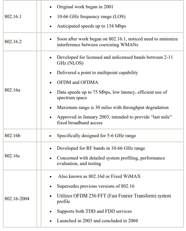
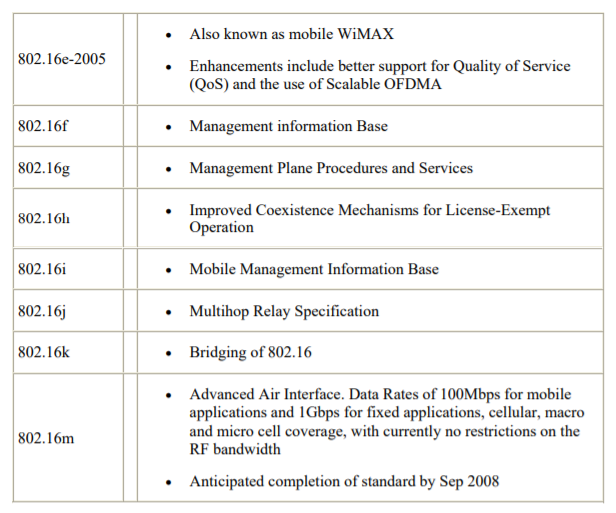
The IEEE 802.16 standard is still being actively developed by the IEEE 802.16 working group. There are many revisions still in the planning stages. Currently, the two versions that are being exploited are 802.16-2004 and 802.16e-2005. IEEE 802.16-2004 is the fixed version while the e-version also handles the mobile piece. Both use OFDM, but 802.16e-2005 uses OFDMA due to its mobile piece. Actual gear and products have started rolling out the past few years, with actual NIC cards being introduced into the market January 2007.
In the next couple years, more and more products will be showing up for commercial use as more and more corporations are looking to incorporate this technology into their communications systems. Future uses and investments of 802.16 will be covered in a later chapter. Table shows the complete list of versions including those still under development.
Clearly, wireless communications will continue to grow and develop as the demand for mobility becomes an important feature in the telecommunications industry. Wireless also has the added benefit of being a cheaper alternative to wired communications. These two features of wireless will enable it to become a more viable solution to many of the challenges facing the communications industry. One of these challenges revolves around the issue of multicasting data in a network.
Key takeaway
Difference between 802.16 and 802.11:
S.No. | 802.16 | 802.11 |
01. | IEEE 802.16 standard defines WiMAX. | IEEE 802.11 standard defines WLAN or WiFi. |
02. | It is designed for long distance/wide area. | It is designed for limited area. |
03. | It provides a coverage range of 7 km to 50 km. | It provides a coverage range of 30 m to 100m. |
04. | 802.16 standard is used for outdoor usage. | 802.11 standard is used for indoor usage. |
05. | It operates on frequencies of 2.4 GHz, 5 GHz. | It operates on frequencies of 2.5 GHz, 3.5 GHz, 5.8GHz. |
06. | Standard variants of 802.16 are 802.16a, 802.16d, 802.16e, 802.16m etc. | Standard variants of 802.11 are 802.11a, 11b, 11g, 11n, 11ac, 11ad etc. |
07. | It provides a data rate of 100 Mbps in a 20 MHz channel. | It provides a data rate of 54 Mbps in 20 MHz channel. |
08. | Large number of customers are connected to this as it covers a wide area. | Limited number of customers/devices are connected which are with in the limited range. |
09. | For encryption purpose it uses Data Encryption Standard with Advanced Encryption Standard. | For encryption purpose it uses Rivest Cipher 4. |
10. | Different QoS options are available like UGS, rtPS, nrtPS, BE, etc | It does not provide any QoS but Supported in IEEE 802.11e. |
11. | Bandwidths varies dynamically as per user requirement from 1.5 to 28 MHz. | Bandwidth variants are 20 MHz, 40MHz, 80MHz and 160 MHz. |
References:
1. Forouzan, Data Communication & Networking, McGraw-Hill Education
2. Lathi, B. P. & Ding, Z., (2010), Modern Digital and Analog Communication Systems, Oxford University Press
3. Stallings, W., (2010), Data and Computer Communications, Pearson.
4. Andrew S. Tanenbaum, “Computer Networks” Pearson.
5. Ajit Pal, “Data Communication and Computer Networks”, PHI
6. Dimitri Bertsekas, Robert G. Gallager, “Data Networks”, Prentice Hall, 1992
7. An analysis of IEEE 802.16 and WiMAX multicast delivery Staub, Patrick A. Monterey, California. Naval Postgraduate School