Unit - 4
Network Layer
Point - to - Point Protocol (PPP) is a communication protocol of the data link layer that is used to transmit multiprotocol data between two directly connected (point-to-point) computers. It is a byte - oriented protocol that is widely used in broadband communications having heavy loads and high speeds. Since it is a data link layer protocol, data is transmitted in frames. It is also known as RFC 1661.
The main services provided by Point - to - Point Protocol are
- Defining the frame format of the data to be transmitted.
- Defining the procedure of establishing link between two points and exchange of data
- Stating the method of encapsulation of network layer data in the frame.
- Stating authentication rules of the communicating devices
- Providing address for network communication.
- Providing connections over multiple links
- Supporting a variety of network layer protocols by providing a range os services
Point - to - Point Protocol is a layered protocol having three components −
Encapsulation Component − It encapsulates the datagram so that it can be transmitted over the specified physical layer.
Link Control Protocol (LCP) − It is responsible for establishing, configuring, testing, maintaining and terminating links for transmission. It also imparts negotiation for set up of options and use of features by the two endpoints of the links.
Authentication Protocols (AP) − These protocols authenticate endpoints for use of services. The two authentication protocols of PPP are
Password Authentication Protocol (PAP)
Challenge Handshake Authentication Protocol (CHAP)
Network Control Protocols (NCPs) − These protocols are used for negotiating the parameters and facilities for the network layer. For every higher-layer protocol supported by PPP, one NCP is there.
Key takeaways
The main services provided by Point - to - Point Protocol are
Defining the frame format of the data to be transmitted. Defining the procedure of establishing link between two points and exchange of data Stating the method of encapsulation of network layer data in the frame. Stating authentication rules of the communicating devices. Providing address for network communication. Providing connections over multiple links. Supporting a variety of network layer protocols by providing a range OS services
A Router is a process of selecting path along which the data can be transferred from source to the destination. Routing is performed by a special device known as a router. A Router works at the network layer in the OSI model and internet layer in TCP/IP model A router is a networking device that forwards the packet based on the information available in the packet header and forwarding table. The routing algorithms are used for routing the packets. The routing algorithm is nothing but a software responsible for deciding the optimal path through which packet can be transmitted. The routing protocols use the metric to determine the best path for the packet delivery. The metric is the standard of measurement such as hop count, bandwidth, delay, current load on the path, etc. used by the routing algorithm to determine the optimal path to the destination. The routing algorithm initializes and maintains the routing table for the process of path determination.
Routing Metrics and Costs
Routing metrics and costs are used for determining the best route to the destination. The factors used by the protocols to determine the shortest path, these factors are known as a metric. Metrics are the network variables used to determine the best route to the destination. For some protocols use the static metrics means that their value cannot be changed and for some other routing protocols use the dynamic metrics means that their value can be assigned by the system administrator.
The most common metric values are given below:
Hop count: Hop count is defined as a metric that specifies the number of passes through internetworking devices such as a router, a packet must travel in a route to move from source to the destination. If the routing protocol considers the hop as a primary metric value, then the path with the least hop count will be considered as the best path to move from source to the destination.
Delay: It is a time taken by the router to process, queue and transmit a datagram to an interface. The protocols use this metric to determine the delay values for all the links along the path end-to-end. The path having the lowest delay value will be considered as the best path.
Bandwidth: The capacity of the link is known as a bandwidth of the link. The bandwidth is measured in terms of bits per second. The link that has a higher transfer rate like gigabit is preferred over the link that has the lower capacity like 56 kb. The protocol will determine the bandwidth capacity for all the links along the path, and the overall higher bandwidth will be considered as the best route.
Load: Load refers to the degree to which the network resource such as a router or network link is busy. A Load can be calculated in a variety of ways such as CPU utilization, packets processed per second. If the traffic increases, then the load value will also be increased. The load value changes with respect to the change in the traffic.
Reliability: Reliability is a metric factor may be composed of a fixed value. It depends on the network links, and its value is measured dynamically. Some networks go down more often than others. After network failure, some network links repaired more easily than other network links. Any reliability factor can be considered for the assignment of reliability ratings, which are generally numeric values assigned by the system administrator.
Types of Routing
Routing can be classified into three categories:
- Static Routing
- Default Routing
- Dynamic Routing
Static Routing
Static Routing is also known as Nonadoptive Routing. It is a technique in which the administrator manually adds the routes in a routing table. A Router can send the packets for the destination along the route defined by the administrator. In this technique, routing decisions are not made based on the condition or topology of the network.
Advantages of Static Routing
- No Overhead: It has ho overhead on the CPU usage of the router. Therefore, the cheaper router can be used to obtain static routing.
- Bandwidth: It has not bandwidth usage between the routers.
- Security: It provides security as the system administrator is allowed only to have control over the routing to a particular network.
Disadvantages of Static Routing:
- For a large network, it becomes a very difficult task to add each route manually to the routing table. The system administrator should have a good knowledge of a topology as he has to add each route manually.
Default Routing
Default Routing is a technique in which a router is configured to send all the packets to the same hop device, and it doesn't matter whether it belongs to a particular network or not. A Packet is transmitted to the device for which it is configured in default routing. Default Routing is used when networks deal with the single exit point. It is also useful when the bulk of transmission networks have to transmit the data to the same hp device. When a specific route is mentioned in the routing table, the router will choose the specific route rather than the default route. The default route is chosen only when a specific route is not mentioned in the routing table.
Dynamic Routing
It is also known as Adaptive Routing. It is a technique in which a router adds a new route in the routing table for each packet in response to the changes in the condition or topology of the network. Dynamic protocols are used to discover the new routes to reach the destination. In Dynamic Routing, RIP and OSPF are the protocols used to discover the new routes. If any route goes down, then the automatic adjustment will be made to reach the destination. The Dynamic protocol should have the following features: All the routers must have the same dynamic routing protocol in order to exchange the routes. If the router discovers any change in the condition or topology, then router broadcast this information to all other routers.
Key takeaway
Advantages of Dynamic Routing:
- It is easier to configure.
- It is more effective in selecting the best route in response to the changes in the condition or topology.
Disadvantages of Dynamic Routing:
- It is more expensive in terms of CPU and bandwidth usage.
- It is less secure as compared to default and static routing.
TCP/IP Reference Model is a four-layered suite of communication protocols. It was developed by the DoD (Department of Defence) in the 1960s. It is named after the two main protocols that are used in the model, namely, TCP and IP. TCP stands for Transmission Control Protocol and IP stands for Internet Protocol.
The four layers in the TCP/IP protocol suite are −
Host-to- Network Layer −It is the lowest layer that is concerned with the physical transmission of data. TCP/IP does not specifically define any protocol here but supports all the standard protocols.
Internet Layer −It defines the protocols for logical transmission of data over the network. The main protocol in this layer is Internet Protocol (IP) and it is supported by the protocols ICMP, IGMP, RARP, and ARP.
Transport Layer − It is responsible for error-free end-to-end delivery of data. The protocols defined here are Transmission Control Protocol (TCP) and User Datagram Protocol (UDP).
Application Layer − This is the topmost layer and defines the interface of host programs with the transport layer services. This layer includes all high-level protocols like Telnet, DNS, HTTP, FTP, SMTP, etc.
The advantages of TCP/IP protocol suite are
- It is an industry–standard model that can be effectively deployed in practical networking problems. It is interoperable, i.e., it allows cross-platform communications among heterogeneous networks.
- It is an open protocol suite. It is not owned by any particular institute and so can be used by any individual or organization.
- It is a scalable, client-server architecture. This allows networks to be added without disrupting the current services.
- It assigns an IP address to each computer on the network, thus making each device to be identifiable over the network. It assigns each site a domain name. It provides name and address resolution services.
The disadvantages of the TCP/IP model are
- It is not generic in nature. So, it fails to represent any protocol stack other than the TCP/IP suite. For example, it cannot describe the Bluetooth connection. It does not clearly separate the concepts of services, interfaces, and protocols. So, it is not suitable to describe new technologies in new networks.
- It does not distinguish between the data link and the physical layers, which has very different functionalities. The data link layer should concern with the transmission of frames. On the other hand, the physical layer should lay down the physical characteristics of transmission. A proper model should segregate the two layers.
- It was originally designed and implemented for wide area networks. It is not optimized for small networks like LAN (local area network) and PAN (personal area network). Among its suite of protocols, TCP and IP were carefully designed and well implemented. Some of the other protocols were developed ad hoc and so proved to be unsuitable in long run. However, due to the popularity of the model, these protocols are being used even 30–40 years after their introduction.
Each IP packet contains both a header (20 or 24 bytes long) and data (variable length). The header includes the IP addresses of the source and destination, plus other fields that help to route the packet. The data is the actual content, such as a string of letters or part of a webpage. The packet carries data using Internet protocols, which is TCP / IP (Transmission Control Protocol / Internet Protocol). Each packet contains part of the message body. Typically, a package usually takes about 1500 bytes.
Each packet is then sent to its destination via the best available route – a route that can be taken by the other packets of the message or any message packets. This makes the network more efficient. For starters, the network can balance the load of several facilities within milliseconds. Second, if there is a problem with one or more computers as the message is being transferred, packets can be routed to alternative sites, ensuring complete delivery of the message.
Depending on the type of network, packets can be referred by various names, such as frames, blocks, cells or segments.
What is IP?
An IP stands for internet protocol. An IP address is assigned to each device connected to a network. Each device uses an IP address for communication. It also behaves as an identifier as this address is used to identify the device on a network. It defines the technical format of the packets. Mainly, both the networks, i.e., IP and TCP, are combined together, so together, they are referred to as a TCP/IP. It creates a virtual connection between the source and the destination.
We can also define an IP address as a numeric address assigned to each device on a network. An IP address is assigned to each device so that the device on a network can be identified uniquely. To facilitate the routing of packets, TCP/IP protocol uses a 32-bit logical address known as IPv4(Internet Protocol version 4).
An IP address consists of two parts, i.e., the first one is a network address, and the other one is a host address.
There are two types of IP addresses:
- IPv4
- IPv6
What is IP4?
IPv4 is a version 4 of IP. It is a current version and the most commonly used IP address. It is a 32-bit address written in four numbers separated by 'dot', i.e., periods. This address is unique for each device.
For example, 66.94.29.13
The above example represents the IP address in which each group of numbers separated by periods is called an Octet. Each number in an octet is in the range from 0-255. This address can produce 4,294,967,296 possible unique addresses.
In today's computer network world, computers do not understand the IP addresses in the standard numeric format as the computers understand the numbers in binary form only. The binary number can be either 1 or 0. The IPv4 consists of four sets, and these sets represent the octet. The bits in each octet represent a number.
Each bit in an octet can be either 1 or 0. If the bit the 1, then the number it represents will count, and if the bit is 0, then the number it represents does not count.
Representation of 8 Bit Octet

The above representation shows the structure of 8- bit octet.
Now, we will see how to obtain the binary representation of the above IP address, i.e., 66.94.29.13
Step 1: First, we find the binary number of 66.

To obtain 66, we put 1 under 64 and 2 as the sum of 64 and 2 is equal to 66 (64+2=66), and the remaining bits will be zero, as shown above. Therefore, the binary bit version of 66 is 01000010.
Step 2: Now, we calculate the binary number of 94.

To obtain 94, we put 1 under 64, 16, 8, 4, and 2 as the sum of these numbers is equal to 94, and the remaining bits will be zero. Therefore, the binary bit version of 94 is 01011110.
Step 3: The next number is 29.

To obtain 29, we put 1 under 16, 8, 4, and 1 as the sum of these numbers is equal to 29, and the remaining bits will be zero. Therefore, the binary bit version of 29 is 00011101.
Step 4: The last number is 13.

To obtain 13, we put 1 under 8, 4, and 1 as the sum of these numbers is equal to 13, and the remaining bits will be zero. Therefore, the binary bit version of 13 is 00001101.
Drawback of IPv4
Currently, the population of the world is 7.6 billion. Every user is having more than one device connected with the internet, and private companies also rely on the internet. As we know that IPv4 produces 4 billion addresses, which are not enough for each device connected to the internet on a planet. Although the various techniques were invented, such as variable- length mask, network address translation, port address translation, classes, inter-domain translation, to conserve the bandwidth of IP address and slow down the depletion of an IP address. In these techniques, public IP is converted into a private IP due to which the user having public IP can also use the internet. But still, this was not so efficient, so it gave rise to the development of the next generation of IP addresses, i.e., IPv6.
Address format
The address format of IPv4:

An IPv4 is a 32-bit decimal address. It contains 4 octets or fields separated by 'dot', and each field is 8-bit in size. The number that each field contains should be in the range of 0-255
What is IPv6?
IPv4 produces 4 billion addresses, and the developers think that these addresses are enough, but they were wrong. IPv6 is the next generation of IP addresses. The main difference between IPv4 and IPv6 is the address size of IP addresses. The IPv4 is a 32-bit address, whereas IPv6 is a 128-bit hexadecimal address. IPv6 provides a large address space, and it contains a simple header as compared to IPv4.
It provides transition strategies that convert IPv4 into IPv6, and these strategies are as follows:
- Dual stacking: It allows us to have both the versions, i.e., IPv4 and IPv6, on the same device.
- Tunneling: In this approach, all the users have IPv6 communicates with an IPv4 network to reach IPv6.
- Network Address Translation: The translation allows the communication between the hosts having a different version of IP.
This hexadecimal address contains both numbers and alphabets. Due to the usage of both the numbers and alphabets, IPv6 is capable of producing over 340 undecillion (3.4*1038) addresses.
IPv6 is a 128-bit hexadecimal address made up of 8 sets of 16 bits each, and these 8 sets are separated by a colon. In IPv6, each hexadecimal character represents 4 bits. So, we need to convert 4 bits to a hexadecimal number at a time
The address format of IPv6:

IPv6 is a 128-bit hexadecimal address. It contains 8 fields separated by a colon, and each field is 16-bit in size.
Key takeaway
Differences between IPv4 and IPv6
| Ipv4 | Ipv6 |
Address length | IPv4 is a 32-bit address. | IPv6 is a 128-bit address. |
Fields | IPv4 is a numeric address that consists of 4 fields which are separated by dot (.). | IPv6 is an alphanumeric address that consists of 8 fields, which are separated by colon. |
Classes | IPv4 has 5 different classes of IP address that includes Class A, Class B, Class C, Class D, and Class E. | IPv6 does not contain classes of IP addresses. |
Number of IP address | IPv4 has a limited number of IP addresses. | IPv6 has a large number of IP addresses. |
VLSM | It supports VLSM (Virtual Length Subnet Mask). Here, VLSM means that Ipv4 converts IP addresses into a subnet of different sizes. | It does not support VLSM. |
Address configuration | It supports manual and DHCP configuration. | It supports manual, DHCP, auto-configuration, and renumbering. |
Address space | It generates 4 billion unique addresses | It generates 340 undecillion unique addresses. |
End-to-end connection integrity | In IPv4, end-to-end connection integrity is unachievable. | In the case of IPv6, end-to-end connection integrity is achievable. |
Security features | In IPv4, security depends on the application. This IP address is not developed in keeping the security feature in mind. | In IPv6, IPSEC is developed for security purposes. |
Address representation | In IPv4, the IP address is represented in decimal. | In IPv6, the representation of the IP address in hexadecimal. |
Fragmentation | Fragmentation is done by the senders and the forwarding routers. | Fragmentation is done by the senders only. |
Packet flow identification | It does not provide any mechanism for packet flow identification. | It uses flow label field in the header for the packet flow identification. |
Checksum field | The checksum field is available in IPv4. | The checksum field is not available in IPv6. |
Transmission scheme | IPv4 is broadcasting. | On the other hand, IPv6 is multicasting, which provides efficient network operations. |
Encryption and Authentication | It does not provide encryption and authentication. | It provides encryption and authentication. |
Number of octets | It consists of 4 octets. | It consists of 8 fields, and each field contains 2 octets. Therefore, the total number of octets in IPv6 is 16. |
1)Design issue-
The basic function of the Transport layer is to accept data from the layer above, split it up into smaller units, pass these data units to the Network layer, and ensure that all the pieces arrive correctly at the other end. All this must be done efficiently and in a way, that isolates the upper layers from the inevitable changes in the hardware technology. The Transport layer also determines what type of service to provide to the Session layer, and, ultimately, to the users of the network. The most popular type of transport connection is an error-free point-to-point channel that delivers messages or bytes in the order in which they were sent. The Transport layer is a true end-to-end layer, all the way from the source to the destination. In other words, a program on the source machine carries on a conversation with a similar program on the destination machine, using the message headers and control messages.
Functions of Transport Layer
- Service Point Addressing: Transport Layer header includes service point address which is port address. This layer gets the message to the correct process on the computer unlike Network Layer, which gets each packet to the correct computer.
- Segmentation and Reassembling: A message is divided into segments; each segment contains sequence number, which enables this layer in reassembling the message. Message is reassembled correctly upon arrival at the destination and replaces packets which were lost in transmission.
- Connection Control: It includes 2 types:
- Connectionless Transport Layer: Each segment is considered as an independent packet and delivered to the transport layer at the destination machine.
- Connection Oriented Transport Layer: Before delivering packets, connection is made with transport layer at the destination machine.
- Flow Control: In this layer, flow control is performed end to end.
- Error Control: Error Control is performed end to end in this layer to ensure that the complete message arrives at the receiving transport layer without any error. Error Correction is done through retransmission.
- Transport Layer in ISO-OSI Model
Design Issues with Transport Layer
1.Accepting data from Session layer, split it into segments and send to the network layer.
2.Ensure correct delivery of data with efficiency.
3.Isolate upper layers from the technological changes.
4.Error control and flow control.
Connection Management
Transport protocols are designed to provide fully reliable communication between processes which must communicate over a less reliable medium such as a packet switching network (which may damage, lose, or duplicate packets, or deliver them out of order). This is typically accomplished by assigning a sequence number and checksum to each packet transmitted, and retransmitting any packets not positively acknowledged by the other side. The use of such mechanisms requires the maintenance of state information describing the progress of data exchange. The initialization and maintenance of this state information constitutes a connection between the two processes, provided by the transport protocol programs on each side of the connection. Since a connection requires significant resources, it is desirable to maintain a connection only while processes are communicating.
This requires mechanisms for opening a connection when needed, and for closing a connection after ensuring that all user data have been properly exchanged. These connection management procedures form and the main subject of this paper. Mechanisms for establishing connections, terminating connections, recovery from crashes or failures of either side, and for resynchronizing a connection are presented. Connection management functions are intimately involved in protocol reliability, and if not designed properly may result in deadlocks or old data eing erroneously delivered in place of current data. Some protocol modeling techniques useful in analyzing connection management are discussed, using verification of connection establishment as an example. The paper is based on experience with the Transmission Control Protocol (TCP), and examples throughout the naper are taken from TCP.
UDP Protocol
In computer networking, the UDP stands for User Datagram Protocol. The David P. Reed developed the UDP protocol in 1980. It is defined in RFC 768, and it is a part of the TCP/IP protocol, so it is a standard protocol over the internet. The UDP protocol allows the computer applications to send the messages in the form of datagrams from one machine to another machine over the Internet protocol (IP) network. The UDP is an alternative communication protocol to the TCP protocol (transmission control protocol). Like TCP, UDP provides a set of rules that governs how the data should be exchanged over the internet. The UDP works by encapsulating the data into the packet and providing its own header information to the packet. Then, this UDP packet is encapsulated to the IP packet and sent off to its destination. Both the TCP and UDP protocols send the data over the internet protocol network, so it is also known as TCP/IP and UDP/IP. There are many differences between these two protocols. UDP enables the process to process communication, whereas the TCP provides host to host communication. Since UDP sends the messages in the form of datagrams, it is considered the best-effort mode of communication. TCP sends the individual packets, so it is a reliable transport medium. Another difference is that the TCP is a connection-oriented protocol whereas, the UDP is a connectionless protocol as it does not require any virtual circuit to transfer the data.
UDP also provides a different port number to distinguish different user requests and also provides the checksum capability to verify whether the complete data has arrived or not; the IP layer does not provide these two services.
Features of UDP protocol
The following are the features of the UDP protocol:
- Transport layer protocol
UDP is the simplest transport layer communication protocol. It contains a minimum amount of communication mechanisms. It is considered an unreliable protocol, and it is based on best-effort delivery services. UDP provides no acknowledgment mechanism, which means that the receiver does not send the acknowledgment for the received packet, and the sender also does not wait for the acknowledgment for the packet that it has sent.
- Connectionless
The UDP is a connectionless protocol as it does not create a virtual path to transfer the data. It does not use the virtual path, so packets are sent in different paths between the sender and the receiver, which leads to the loss of packets or received out of order.
Ordered delivery of data is not guaranteed.
In the case of UDP, the datagrams are sent in some order will be received in the same order is not guaranteed as the datagrams are not numbered.
- Ports
The UDP protocol uses different port numbers so that the data can be sent to the correct destination. The port numbers are defined between 0 and 1023.
- Faster transmission
UDP enables faster transmission as it is a connectionless protocol, i.e., no virtual path is required to transfer the data. But there is a chance that the individual packet is lost, which affects the transmission quality. On the other hand, if the packet is lost in TCP connection, that packet will be resent, so it guarantees the delivery of the data packets.
- Acknowledgment mechanism
The UDP does have any acknowledgment mechanism, i.e., there is no handshaking between the UDP sender and UDP receiver. If the message is sent in TCP, then the receiver acknowledges that I am ready, then the sender sends the data. In the case of TCP, the handshaking occurs between the sender and the receiver, whereas in UDP, there is no handshaking between the sender and the receiver.
- Segments are handled independently.
Each UDP segment is handled individually of others as each segment takes different path to reach the destination. The UDP segments can be lost or delivered out of order to reach the destination as there is no connection setup between the sender and the receiver.
- Stateless
It is a stateless protocol that means that the sender does not get the acknowledgement for the packet which has been sent.
Why do we require the UDP protocol?
As we know that the UDP is an unreliable protocol, but we still require a UDP protocol in some cases. The UDP is deployed where the packets require a large amount of bandwidth along with the actual data. For example, in video streaming, acknowledging thousands of packets is troublesome and wastes a lot of bandwidth. In the case of video streaming, the loss of some packets couldn't create a problem, and it can also be ignored.
UDP Header Format
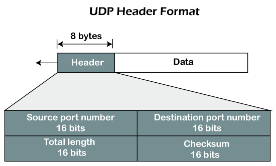
Fig – UDP header format
In UDP, the header size is 8 bytes, and the packet size is upto 65,535 bytes. But this packet size is not possible as the data needs to be encapsulated in the IP datagram, and an IP packet, the header size can be 20 bytes; therefore, the maximum of UDP would be 65,535 minus 20. The size of the data that the UDP packet can carry would be 65,535 minus 28 as 8 bytes for the header of the UDP packet and 20 bytes for IP header.
The UDP header contains four fields:
- Source port number: It is 16-bit information that identifies which port is going t send the packet.
- Destination port number: It identifies which port is going to accept the information. It is 16-bit information which is used to identify application-level service on the destination machine.
- Length: It is 16-bit field that specifies the entire length of the UDP packet that includes the header also. The minimum value would be 8-byte as the size of the header is 8 bytes.
- Checksum: It is a 16-bits field, and it is an optional field. This checksum field checks whether the information is accurate or not as there is the possibility that the information can be corrupted while transmission. It is an optional field, which means that it depends upon the application, whether it wants to write the checksum or not. If it does not want to write the checksum, then all the 16 bits are zero; otherwise, it writes the checksum. In UDP, the checksum field is applied to the entire packet, i.e., header as well as data part whereas, in IP, the checksum field is applied to only the header field.
Concept of Queuing in UDP protocol
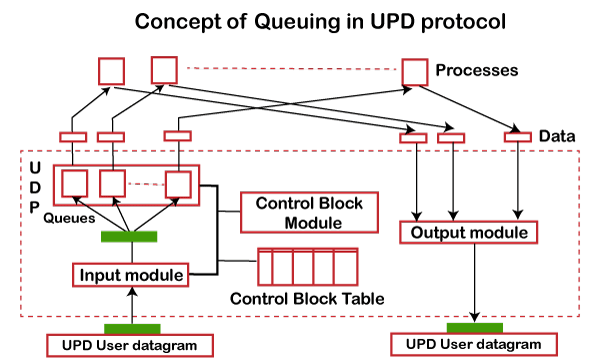
Fig - Concept of Queuing in UDP protocol
In UDP protocol, numbers are used to distinguish the different processes on a server and client. We know that UDP provides a process-to-process communication. The client generates the processes that need services while the server generates the processes that provide services. The queues are available for both the processes, i.e., two queues for each process. The first queue is the incoming queue that receives the messages, and the second one is the outgoing queue that sends the messages. The queue functions when the process is running. If the process is terminated then the queue will also get destroyed.
UDP handles the sending and receiving of the UDP packets with the help of the following components:
- Input queue: The UDP packets uses a set of queues for each process.
- Input module: This module takes the user datagram from the IP, and then it finds the information from the control block table of the same port. If it finds the entry in the control block table with the same port as the user datagram, it enqueues the data.
- Control Block Module: It manages the control block table.
- Control Block Table: The control block table contains the entry of open ports.
- Output module: The output module creates and sends the user datagram.
Several processes want to use the services of UDP. The UDP multiplexes and demultiplexes the processes so that the multiple processes can run on a single host.
Limitations
- It provides an unreliable connection delivery service. It does not provide any services of IP except that it provides process-to-process communication.
- The UDP message can be lost, delayed, duplicated, or can be out of order.
- It does not provide a reliable transport delivery service. It does not provide any acknowledgment or flow control mechanism. However, it does provide error control to some extent.
Advantages
- It produces a minimal number of overheads.
Key takeaways
- In computer networking, the UDP stands for User Datagram Protocol. The David P. Reed developed the UDP protocol in 1980. It is defined in RFC 768, and it is a part of the TCP/IP protocol, so it is a standard protocol over the internet. The UDP protocol allows the computer applications to send the messages in the form of datagrams from one machine to another machine over the Internet protocol (IP) network. The UDP is an alternative communication protocol to the TCP protocol (transmission control protocol). Like TCP, UDP provides a set of rules that governs how the data should be exchanged over the internet. The UDP works by encapsulating the data into the packet and providing its own header information to the packet. Then, this UDP packet is encapsulated to the IP packet and sent off to its destination. Both the TCP and UDP protocols send the data over the internet protocol network, so it is also known as TCP/IP and UDP/IP. There are many differences between these two protocols. UDP enables the process to process communication, whereas the TCP provides host to host communication. Since UDP sends the messages in the form of datagrams, it is considered the best-effort mode of communication. TCP sends the individual packets, so it is a reliable transport medium. Another difference is that the TCP is a connection-oriented protocol whereas, the UDP is a connectionless protocol as it does not require any virtual circuit to transfer the data.
- UDP also provides a different port number to distinguish different user requests and also provides the checksum capability to verify whether the complete data has arrived or not; the IP layer does not provide these two services.
TCP
TCP stands for Transmission Control Protocol. It is a transport layer protocol that facilitates the transmission of packets from source to destination. It is a connection-oriented protocol that means it establishes the connection prior to the communication that occurs between the computing devices in a network. This protocol is used with an IP protocol, so together, they are referred to as a TCP/IP.
The main functionality of the TCP is to take the data from the application layer. Then it divides the data into a several packets, provides numbering to these packets, and finally transmits these packets to the destination. The TCP, on the other side, will reassemble the packets and transmits them to the application layer. As we know that TCP is a connection-oriented protocol, so the connection will remain established until the communication is not completed between the sender and the receiver.
Features of TCP protocol
The following are the features of a TCP protocol:
- Transport Layer Protocol
TCP is a transport layer protocol as it is used in transmitting the data from the sender to the receiver.
- Reliable
TCP is a reliable protocol as it follows the flow and error control mechanism. It also supports the acknowledgment mechanism, which checks the state and sound arrival of the data. In the acknowledgment mechanism, the receiver sends either positive or negative acknowledgment to the sender so that the sender can get to know whether the data packet has been received or needs to resend.
- Order of the data is maintained
This protocol ensures that the data reaches the intended receiver in the same order in which it is sent. It orders and numbers each segment so that the TCP layer on the destination side can reassemble them based on their ordering.
- Connection-oriented
It is a connection-oriented service that means the data exchange occurs only after the connection establishment. When the data transfer is completed, then the connection will get terminated.
- Full duplex
It is a full-duplex means that the data can transfer in both directions at the same time.
- Stream-oriented
TCP is a stream-oriented protocol as it allows the sender to send the data in the form of a stream of bytes and also allows the receiver to accept the data in the form of a stream of bytes. TCP creates an environment in which both the sender and receiver are connected by an imaginary tube known as a virtual circuit. This virtual circuit carries the stream of bytes across the internet.
Need of Transport Control Protocol
In the layered architecture of a network model, the whole task is divided into smaller tasks. Each task is assigned to a particular layer that processes the task. In the TCP/IP model, five layers are application layer, transport layer, network layer, data link layer, and physical layer. The transport layer has a critical role in providing end-to-end communication to the directly application processes. It creates 65,000 ports so that the multiple applications can be accessed at the same time. It takes the data from the upper layer, and it divides the data into smaller packets and then transmits them to the network layer.
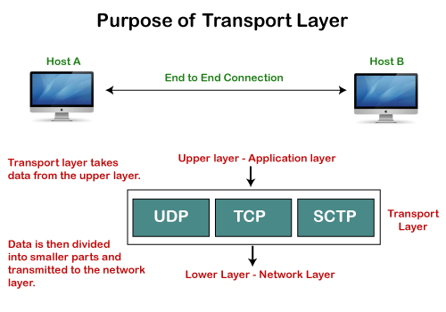
Fig – Purpose of transport layer
Working of TCP
In TCP, the connection is established by using three-way handshaking. The client sends the segment with its sequence number. The server, in return, sends its segment with its own sequence number as well as the acknowledgement sequence, which is one more than the client sequence number. When the client receives the acknowledgment of its segment, then it sends the acknowledgment to the server. In this way, the connection is established between the client and the server.
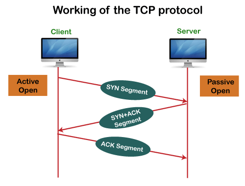
Fig – Working of the TCP protocol
Advantages of TCP
- It provides a connection-oriented reliable service, which means that it guarantees the delivery of data packets. If the data packet is lost across the network, then the TCP will resend the lost packets.
- It provides a flow control mechanism using a sliding window protocol.
- It provides error detection by using checksum and error control by using Go Back or ARP protocol.
- It eliminates the congestion by using a network congestion avoidance algorithm that includes various schemes such as additive increase/multiplicative decrease (AIMD), slow start, and congestion window.
Disadvantage of TCP
It increases a large amount of overhead as each segment gets its own TCP header, so fragmentation by the router increases the overhead.
TCP Header format
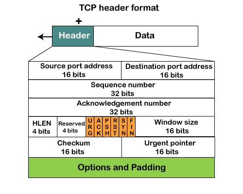
Fig – TCP header format
- Source port: It defines the port of the application, which is sending the data. So, this field contains the source port address, which is 16 bits.
- Destination port: It defines the port of the application on the receiving side. So, this field contains the destination port address, which is 16 bits.
- Sequence number: This field contains the sequence number of data bytes in a particular session.
- Acknowledgment number: When the ACK flag is set, then this contains the next sequence number of the data byte and works as an acknowledgment for the previous data received. For example, if the receiver receives the segment number 'x', then it responds 'x+1' as an acknowledgment number.
- HLEN: It specifies the length of the header indicated by the 4-byte words in the header. The size of the header lies between 20 and 60 bytes. Therefore, the value of this field would lie between 5 and 15.
- Reserved: It is a 4-bit field reserved for future use, and by default, all are set to zero.
- Flags
There are six control bits or flags:- URG: It represents an urgent pointer. If it is set, then the data is processed urgently.
- ACK: If the ACK is set to 0, then it means that the data packet does not contain an acknowledgment.
- PSH: If this field is set, then it requests the receiving device to push the data to the receiving application without buffering it.
- RST: If it is set, then it requests to restart a connection.
- SYN: It is used to establish a connection between the hosts.
- FIN: It is used to release a connection, and no further data exchange will happen.
- Window size
It is a 16-bit field. It contains the size of data that the receiver can accept. This field is used for the flow control between the sender and receiver and also determines the amount of buffer allocated by the receiver for a segment. The value of this field is determined by the receiver.
- Checksum
It is a 16-bit field. This field is optional in UDP, but in the case of TCP/IP, this field is mandatory. - Urgent pointer
It is a pointer that points to the urgent data byte if the URG flag is set to 1. It defines a value that will be added to the sequence number to get the sequence number of the last urgent byte.
- Options
It provides additional options. The optional field is represented in 32-bits. If this field contains the data less than 32-bit, then padding is required to obtain the remaining bits.
What is a TCP port?
The TCP port is a unique number assigned to different applications. For example, we have opened the email and games applications on our computer; through email application, we want to send the mail to the host, and through games application, we want to play the online games. In order to do all these tasks, different unique numbers are assigned to these applications. Each protocol and address have a port known as a port number. The TCP (Transmission control protocol) and UDP (User Datagram Protocol) protocols mainly use the port numbers.
A port number is a unique identifier used with an IP address. A port is a 16-bit unsigned integer, and the total number of ports available in the TCP/IP model is 65,535 ports. Therefore, the range of port numbers is 0 to 65535. In the case of TCP, the zero-port number is reserved and cannot be used, whereas, in UDP, the zero port is not available. IANA (Internet Assigned Numbers Authority) is a standard body that assigns the port numbers.
Example of port number:
192.168.1.100: 7
In the above case, 192.168.1.100 is an IP address, and 7 is a port number.
To access a particular service, the port number is used with an IP address. The range from 0 to 1023 port numbers are reserved for the standard protocols, and the other port numbers are user-defined.
Why do we require port numbers?
A single client can have multiple connections with the same server or multiple servers. The client may be running multiple applications at the same time. When the client tries to access some service, then the IP address is not sufficient to access the service. To access the service from a server, the port number is required. So, the transport layer plays a major role in providing multiple communication between these applications by assigning a port number to the applications.
Classification of port numbers
The port numbers are divided into three categories:
- Well-known ports
- Registered ports
- Dynamic ports

Well-known ports
The range of well-known port is 0 to 1023. The well-known ports are used with those protocols that serve common applications and services such as HTTP (Hypertext transfer protocol), IMAP (Internet Message Access Protocol), SMTP (Simple Mail Transfer Protocol), etc. For example, we want to visit some websites on an internet; then, we use http protocol; the http is available with a port number 80, which means that when we use http protocol with an application then it gets port number 80. It is defined that whenever http protocol is used, then port number 80 will be used. Similarly, with other protocols such as SMTP, IMAP; well-known ports are defined. The remaining port numbers are used for random applications.
Registered ports
The range of registered port is 1024 to 49151. The registered ports are used for the user processes. These processes are individual applications rather than the common applications that have a well-known port.
Dynamic ports
The range of dynamic port is 49152 to 65535. Another name of the dynamic port is ephemeral ports. These port numbers are assigned to the client application dynamically when a client creates a connection. The dynamic port is identified when the client initiates the connection, whereas the client knows the well-known port prior to the connection. This port is not known to the client when the client connects to the service.
TCP and UDP header
As we know that both TCP and UDP contain source and destination port numbers, and these port numbers are used to identify the application or a server both at the source and the destination side. Both TCP and UDP use port numbers to pass the information to the upper layers.
Let's understand this scenario.
Suppose a client is accessing a web page. The TCP header contains both the source and destination port.
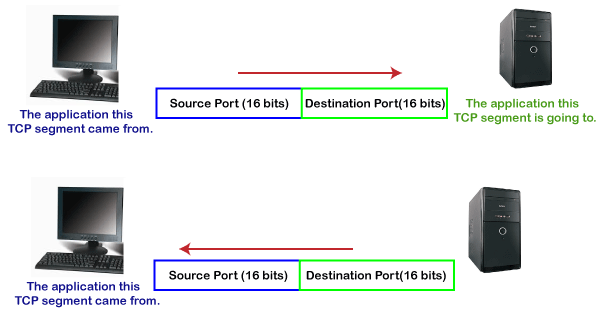
Client-side
In the above diagram,
Source Port: The source port defines an application to which the TCP segment belongs to, and this port number is dynamically assigned by the client. This is basically a process to which the port number is assigned.
Destination port: The destination port identifies the location of the service on the server so that the server can serve the request of the client.
Server-side
In the above diagram,
Source port: It defines the application from where the TCP segment came from.
Destination port: It defines the application to which the TCP segment is going to.
In the above case, two processes are used:
Encapsulation: Port numbers are used by the sender to tell the receiver which application it should use for the data.
Decapsulation: Port numbers are used by the receiver to identify which application should it sends the data to.
Let's understand the above example by using all three ports, i.e., well-known port, registered port, and dynamic port.
First, we look at a well-known port.
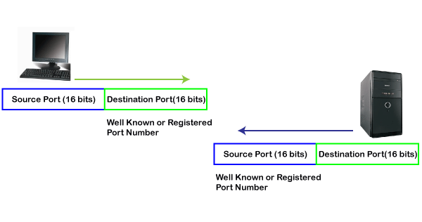
The well-known ports are the ports that serve the common services and applications like http, ftp, smtp, etc. Here, the client uses a well-known port as a destination port while the server uses a well-known port as a source port. For example, the client sends an http request, then, in this case, the destination port would be 80, whereas the http server is serving the request so its source port number would be 80.
Now, we look at the registered port.
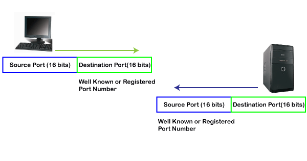
The registered port is assigned to the non-common applications. Lots of vendor applications use this port. Like the well-known port, client uses this port as a destination port whereas the server uses this port as a source port.
At the end, we see how dynamic port works in this scenario.
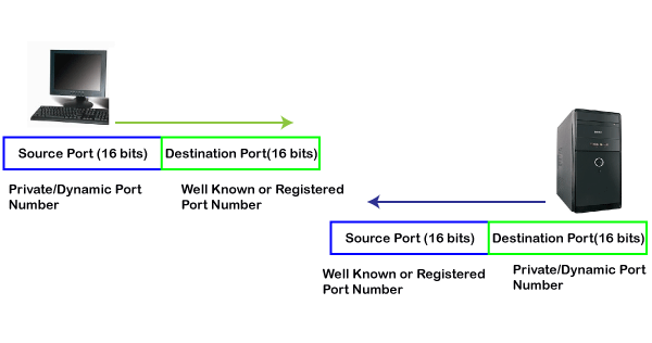
The dynamic port is the port that is dynamically assigned to the client application when initiating a connection. In this case, the client uses a dynamic port as a source port, whereas the server uses a dynamic port as a destination port. For example, the client sends an http request; then in this case, destination port would be 80 as it is a http request, and the source port will only be assigned by the client. When the server serves the request, then the source port would be 80 as it is an http server, and the destination port would be the same as the source port of the client. The registered port can also be used in place of a dynamic port.
Let's look at the below example.
Suppose client is communicating with a server, and sending the http request. So, the client sends the TCP segment to the well-known port, i.e., 80 of the HTTP protocols. In this case, the destination port would be 80 and suppose the source port assigned dynamically by the client is 1028. When the server responds, the destination port is 1028 as the source port defined by the client is 1028, and the source port at the server end would be 80 as the HTTP server is responding to the request of the client.
Key takeaways
- TCP stands for Transmission Control Protocol. It is a transport layer protocol that facilitates the transmission of packets from source to destination. It is a connection-oriented protocol that means it establishes the connection prior to the communication that occurs between the computing devices in a network. This protocol is used with an IP protocol, so together, they are referred to as a TCP/IP.
- The main functionality of the TCP is to take the data from the application layer. Then it divides the data into a several packets, provides numbering to these packets, and finally transmits these packets to the destination. The TCP, on the other side, will reassemble the packets and transmits them to the application layer. As we know that TCP is a connection-oriented protocol, so the connection will remain established until the communication is not completed between the sender and the receiver.
It is an International Telecommunication Union- Telecommunications Standards Section (ITU-T) efficient for call relay and it transmits all information including multiple service types such as data, video or voice which is conveyed in small fixed size packets called cells. Cells are transmitted asynchronously and the network is connection oriented.
ATM is a technology which has some event in the development of broadband ISDN in 1970s and 1980s, which can be considered an evolution of packet switching. Each cell is 53 bytes long – 5 bytes header and 48 bytes payload. Making an ATM call requires first sending a message to set up a connection.
Subsequently all cells follow the same path to the destination. It can handle both constant rate traffic and variable rate traffic. Thus it can carry multiple types of traffic with end-to-end quality of service. ATM is independent of transmission medium, they maybe sent on a wire or fiber by themselves or they may also be packaged inside the payload of other carrier systems. ATM networks use “Packet” or “cell” Switching with virtual circuits. It’s design helps in the implementation of high performance multimedia networking.
ATM Cell Format –
As information is transmitted in ATM in the form of fixed size units called cells. As known already each cell is 53 bytes long which consists of 5 bytes header and 48 bytes payload.

Fig: ATM Cell Format
Asynchronous Transfer Mode can be of two format types which are as follows:
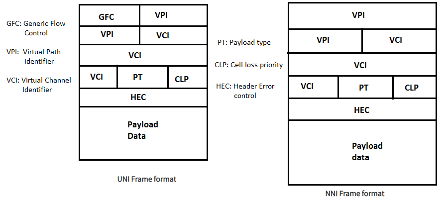
Fig: Formats of ATM
- UNI Header: which is used within private networks of ATM for communication between ATM endpoints and ATM switches. It includes the Generic Flow Control (GFC) field.
- NNI Header: is used for communication between ATM switches, and it does not include the Generic Flow Control(GFC) instead it includes a Virtual Path Identifier (VPI) which occupies the first 12 bits.
Working of ATM:
ATM standard uses two types of connections. i.e., Virtual path connections (VPCs) which consists of Virtual channel connections (VCCs) bundled together which is a basic unit carrying single stream of cells from user to user. A virtual path can be created end-to-end across an ATM network, as it does not routs the cells to a particular virtual circuit. In case of major failure all cells belonging to a particular virtual path are routed the same way through ATM network, thus helping in faster recovery.
Switches connected to subscribers uses both VPIs and VCIs to switch the cells which are Virtual Path and Virtual Connection switches that can have different virtual channel connections between them, serving the purpose of creating a virtual trunk between the switches which can be handled as a single entity. It’s basic operation is straightforward by looking up the connection value in the local translation table determining the outgoing port of the connection and the new VPI/VCI value of connection on that link.
ATM vs DATA Networks (Internet) –
- ATM is a “virtual circuit” based: the path is reserved before transmission. While, Internet Protocol (IP) is connectionless and end-to-end resource reservations not possible. RSVP is a new signaling protocol in the internet.
- ATM Cells: Fixed or small size and Tradeoff is between voice or data. While, IP packets are of variable size.
- Addressing: ATM uses 20-byte global NSAP addresses for signaling and 32-bit locally assigned labels in cells. While, IP uses 32-bit global addresses in all packets.
ATM Layers:
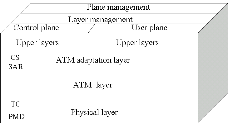
Fig: ATM Layers
ATM Adaption Layer (AAL) –
It is meant for isolating higher layer protocols from details of ATM processes and prepares for conversion of user data into cells and segments it into 48-byte cell payloads. AAL protocol excepts transmission from upper layer services and help them in mapping applications, e.g., voice, data to ATM cells.
Physical Layer –
- It manages the medium-dependent transmission and is divided into two parts physical medium-dependent sublayer and transmission convergence sublayer. Main functions are as follows:
- It converts cells into a bit stream.
- It controls the transmission and receipt of bits in the physical medium.
- It can track the ATM cell boundaries.
- Looks for the packaging of cells into appropriate type of frames.
ATM Layer –
It handles transmission, switching, congestion control, cell header processing, sequential delivery, etc., and is responsible for simultaneously sharing the virtual circuits over the physical link known as cell multiplexing and passing cells through ATM network known as cell relay making use of the VPI and VCI information in the cell header.
ATM Applications:
- ATM WANs –
It can be used as a WAN to send cells over long distances, router serving as a end-point between ATM network and other networks, which has two stacks of protocol.
- Multimedia virtual private networks and managed services –
It helps in managing ATM, LAN, voice and video services and is capable of full-service virtual private-networking, which includes integrated access of multimedia.
- Frame relay backbone –
Frame relay services are used as a networking infrastructure for a range of data services and enabling frame relay ATM service to Internetworking services.
- Residential broadband networks –
ATM is by choice provides the networking infrastructure for the establishment of residential broadband services in search for highly scalable solutions.
- Carrier infrastructure for telephone and private line networks –
To make more effective use of SONET/SDH fiber infrastructures by building the ATM infrastructure for carrying the telephonic and private-line traffic.
Key takeaway
The ATM network is
- Driven by the integration of services and performance requirements of both telephony and data networking: “broadband integrated service vision” (B-ISON).
- Telephone networks support a single quality of service and is expensive to boot.
- Internet supports no quality of service but is flexible and cheap.
- ATM networks were meant to support a range of service qualities at a reasonable cost- intended to subsume both the telephone network and the Internet.
1)Design Issue
The Session Layer allows users on different machines to establish active communication sessions between them. Its main aim is to establish, maintain and synchronize the interaction between communicating systems. Session layer manages and synchronize the conversation between two different applications. In Session layer, streams of data are marked and are resynchronized properly, so that the ends of the messages are not cut prematurely and data loss is avoided.
Functions of Session Layer
1.Dialog Control: This layer allows two systems to start communication with each other in half-duplex or full-duplex.
2.Token Management: This layer prevents two parties from attempting the same critical operation at the same time.
3.Synchronization: This layer allows a process to add checkpoints which are considered as synchronization points into stream of data. Example: If a system is sending a file of 800 pages, adding checkpoints after every 50 pages is recommended. This ensures that 50-page unit is successfully received and acknowledged. This is beneficial at the time of crash as if a crash happens at page number 110; there is no need to retransmit 1 to100 pages.
Design Issues with Session Layer
1.To allow machines to establish sessions between them in a seamless fashion.
2.Provide enhanced services to the user.
3.To manage dialog control.
4.To provide services such as Token management and Synchronization.
Remote Procedure Call (RPC)
Remote Procedure Call (RPC) provides a different paradigm for accessing network services. Instead of accessing remote services by sending and receiving messages, a client invokes services by making a local procedure call. The local procedure hides the details of the network communication.
When making a remote procedure call:
The calling environment is suspended, procedure parameters are transferred across the network to the environment where the procedure is to execute, and the procedure is executed there.
When the procedure finishes and produces its results, its results are transferred back to the calling environment, where execution resumes as if returning from a regular procedure call. The main goal of RPC is to hide the existence of the network from a program.
RPC doesn't quite fit into the OSI model:
The message-passing nature of network communication is hidden from the user. The user doesn't first open a connection, read and write data, and then close the connection. Indeed, a client often doesn’t not even know they are using the network!
RPC often omits many of the protocol layers to improve performance. Even a small performance improvement is important because a program may invoke RPCs often. For example, on (diskless) Sun workstations, every file access is made via an RPC.
RPC is especially well suited for client-server (e.g., query-response) interaction in which the flow of control alternates between the caller and callee. Conceptually, the client and server do not both execute at the same time. Instead, the thread of execution jumps from the caller to the callee and then back again.
The following steps take place during an RPC:
A client invokes a client stub procedure, passing parameters in the usual way. The client stub resides within the client's own address space.
The client stub marshalls the parameters into a message. Marshalling includes converting the representation of the parameters into a standard format, and copying each parameter into the message.
The client stub passes the message to the transport layer, which sends it to the remote server machine.
On the server, the transport layer passes the message to a server stub, which demarshalls the parameters and calls the desired server routine using the regular procedure call mechanism.
When the server procedure completes, it returns to the server stub (e.g., via a normal procedure call return), which marshalls the return values into a message. The server stub then hands the message to the transport layer.
The transport layer sends the result message back to the client transport layer, which hands the message back to the client stub.
The client stub demarshalls the return parameters and execution return to the caller.
Key takeaway
The main aim of Session Layer is to establish, maintain and synchronize the interaction between communicating systems. Session layer manages and synchronize the conversation between two different applications. In Session layer, streams of data are marked and are resynchronized properly, so that the ends of the messages are not cut prematurely and data loss is avoided.
References:
1. Forouzan, Data Communication & Networking, McGraw-Hill Education
2. Lathi, B. P. & Ding, Z., (2010), Modern Digital and Analog Communication Systems, Oxford University Press
3. Stallings, W., (2010), Data and Computer Communications, Pearson.
4. Andrew S. Tanenbaum, “Computer Networks” Pearson.
5. Ajit Pal, “Data Communication and Computer Networks”, PHI
6. Dimitri Bertsekas, Robert G. Gallager, “Data Networks”, Prentice Hall, 1992