Unit-1
Evolution of Mobile Radio Communication Fundamentals
The history of wireless follows following hierarchy. After the Second World War many national and International projects in the area of wireless communications were triggered off.
In ancient times the light was modulated either ON or OFF pattern used for wireless communication. Flags were used to signal code words. Smoke signals were used in wireless communication as early as 150 BC
- In 1982 the European Conference of Postal and Telecommunications Administrations founded working group.
- In 1987 the Global System for Mobile communications standard was available
- In 1991 in Switzerland the first devices are presented
- In 1995SMS was available
- In 1998, Universal Mobile Telecommunication Systems (UMTS) developed by Europeans.
- In 1999, the 802.11b, Bluetooth was standardized.
- In 2000, General Packet Radio Service (GPRS) IEEE802.11a was developed
- In 2001, International Mobile Telecommunications (IMT – d-2000) was standardized
- The year 2007, is the fourth generation the Internet based.
Key takeaway
The development in the wireless system is explained. Old times used light On and OFF for wireless communication.
Mobile computing is an interaction between human and computer by which a computer is expected to be motivating during normal usage. Mobile computing involves software, hardware and mobile communication. Respectively, mobile software deals with the requirements of mobile applications. Also, hardware includes the components and devices which are needed for mobility. Communication issues include ad-hoc and infrastructure networks, protocols, communication properties, data encryption and concrete technologies.
Mobile Computing is a technology that allows transmission of data, voice and video via a computer or any other wireless enabled device without having to be connected to a fixed physical link.
In the last 10 years, the rise of mobile phones as well as laptops has dramatically increased the availability of mobile devices to businesses and home users. More recently, smaller portable devices such as PDAs and especially embedded devices (e.g. Washing machines, sensors) have slowly changed the way humans live and think of computers.
Mobile computing is associated with the mobility of hardware, data and software in computer applications. The study of this new area of computing has prompted the need to rethink carefully about the way in which mobile network and systems are conceived. Even though mobile and traditional distributed systems may appear to be closely related, there are a number of factors that differentiate the two, especially in terms of type of device (fixed/mobile), network connection (permanent/intermittent) and execution context (static/dynamic).
A cellular or mobile phone is a long range portable electronic device for communication over long distance. Current Mobile Phones can support many latest services such as SMS, GPRS, MMS, email, packet switching, WAP, Bluetooth and many more. Most of the mobile phones connect to the cellular networks and which are further connected with the PSTN (Public switching telephone network). Besides mobile communications, there is a wide range of mobile products available such mobile scanners, mobile printers and mobile labellers.
Conceptually, computing can be seen as: USER ⇔ COMP.SYS ⇔ ENVIRONMENT
Key takeaway
A cellular or mobile phone is a long range portable electronic device for communication over long distance.
Mobile computing is an interaction between human and computer by which a computer is expected to be motivating during normal usage.
Two types of traffic channels used:
- Full Rate Traffic Channels (TCH\F): This channel carries information at rate of 22.8 Kbps.
- Half Rate Traffic Channels (TCH\H): This channel carries information at rate of 11.4 Kbps.
SIGNALLING CHANNELS
Signalling channel carries control information to enable the system to operate correctly.
There are three main categories of signalling channels in GSM which are further divided in several categories
1. BROADCAST CHANNELS (BCH)
- Broadcast Control Channel (BCCH)
- Frequency Correction Channel (FCCH)
- Synchronization Channel (SCH)
- Cell Broadcast Channel (CBCH)
2. COMMON CONTROL CHANNELS (CCCH)
- Paging Channel (PCH)
- Random Access Channel (RACH)
- Access Grant Channel (AGCH)
3. DEDICATED CONTROL CHANNELS (DCCH)
- Standalone Dedicated Control Channel (SDCCH)
- Fast Associated Control Channel (FACCH)
- Slow Associated Control Channel (SACCH)
BROADCAST CONTROL CHANNEL (BCCH) – DOWNLINK
- Broadcasts Network and Cell specific information required to identify the network and gain access.
- Broadcast parameters include Location Area Code (LAC), Mobile Network Code (MNC), Control Channel Structures, BCCH frequencies of neighbouring Cells and other access parameters.
FREQUENCY CORRECTION CHANNEL (FCCH) – DOWNLINK
This channel contains frequency correction bursts, used by the mobiles for frequency correction.
Bears information for frequency Synchronization.
SYNCHRONISATIO CHANNEL (SCH) – DOWNLINK
This channel is used by the MS to learn the Base Station Information Code (BSIC) as well as the TDMA frame number (FN).
6 bits of BSIC having two parts. 3 bits NCC and 3 bits BCC. NCC stands for Network Colour Code and used to identify the BTS for which measurement is made. BCC stands for Base-Station Colour Code and used for a better transmission in case of interference.
BICS avoids ambiguity or interference which can arise when a Mobile Station can receive SCH from two cells using the same BCCH frequency.
CELL BROADCAST CONTROL CHANNEL (CBCH) – DOWNLINK
This channel is used to broadcast specific information to network subscribers; such as weather, traffic, sports, stocks and other public services and announcement.
This channel is assigned with SDCCH and usually occupies the second sub slot of the SDCCH.
PAGING CHANNEL (PCH) – DOWNLINK
This channel is used for alerting to Mobile Subscribers for incoming calls, SMS and other mobility services.
-Every MS in a cell periodically listen to this channel.
RANDOM ACCESS CHANNEL (RACCH) – UPLINK
-This channel is used by a MS seeking attention of the BTS. When MS wants to initiate dialogue with network, this channel is used to send request to the network for a dedicated resource.
The real dialogue between MS and Network will take place on the dedicated channel.
If the request is not granted within a specific time period by the network, the MS repeats the request on the RACCH.
ACCESS GRANT CHANNEL (AGCH) - DOWNLINK
This channel is used by a BTS to notify the MS of the assignment of an initial SDCCH for initial signaling.
In response to request from MS on RACH, the network allocates a specific dedicated signaling channel (SDCCH) for further communication. This response is sent on AGCH.
STAND-ALONE DEDICATED CONTROL CHANNEL (SDCCH) –UPLINK/DOWNLINK
In response of RACCH, network allocates SDCCH over AGCH for further communication between MS and BTS.
This channel is used for the Location Update, Voice Call Set up and SMS.
FAST ASSOCIATED CONTROL CHANNEL (FACCH) – UPLINK/DOWNLINK
This channel is used to convey Handover information.
There is no TS and frame allocation dedicated to this channel. This channel can be associated with SDCCH or TCH and works on the principle of stealing. The burst of TCH is replaced by FACCH signaling when required.
SLOW ASSOCIATED CONTROL CHANNEL (SACCH) – UPLINK/DOWNLINK
This channel is always associated with TCH or SDDCH used for control and supervision of signals associated with the traffic channels.
Used to convey the periodic carrier-signal strength measurements to the network, transmit power control and timing advance.
Key takeaway
There are three main categories of signalling channels in GSM which are further divided in several categories
BROADCAST CHANNELS (BCH), COMMON CONTROL CHANNELS (CCCH), DEDICATED CONTROL CHANNELS (DCCH)
The cellular system is replaced by large number of base stations (BS) which are hexagonal cells. They cover certain range of areas.
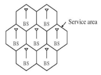
Fig 1 Cellular Structure
For having the communication in cellular structure, we need Mobile station (MS). In these types of structures, the MS communicates with the BS of cell. This is the location of MS in a BS cell. This BS acts as a gateway. For establishing connections, the MS needs to be in the range of the system. The figure below shows the same.
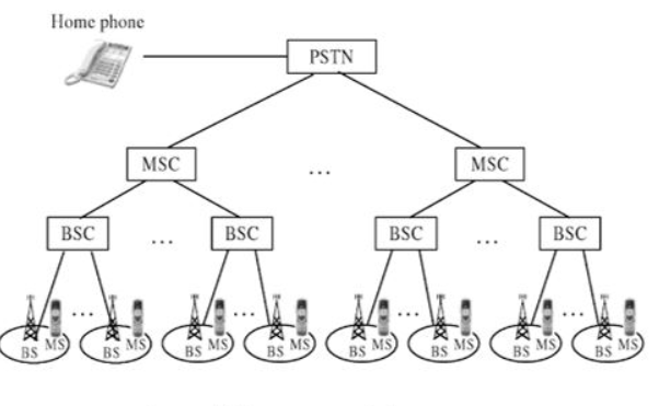
Fig 2 Cellular system infrastructure
Each base station controller (BSC) consists of MS and a BS. These BSC are then connected to the Mobile switching Centre (MSC). These MSC are then connected to a Public Switch Telephone Network (PSTN) and the Asynchronous Transfer Mode (ATM).
A base station consists of several base transceiver stations (BTS) and a BSC. The antenna and tower are the parts of BTS. The BTS system consists of towers and antennas.
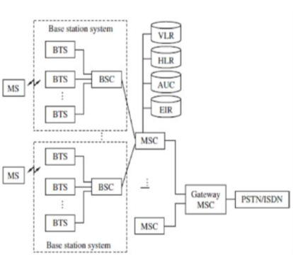
Fig 3 Generic block diagram of cell structure
The Home location register (HLR) is located at MSC. The MS is registered there only in the home location. The visitor location register (VLR) and HLR support mobility and helps to use one number i.e. same number anywhere in world. The VLR has information about all MS.
The authentication and encryption are provided by Authentication centre (AUC). The database which provides identity and information about the mobile is equipment identity register (EIR).
Whenever there is a call it is directed to HLR where home MS is registered. This is then forwarded to VLR of MSC where MS is located currently.
Key takeaway
- Each base station controller (BSC) consists of MS and a BS
- These MSC are then connected to a Public Switch Telephone Network (PSTN) and the Asynchronous Transfer Mode (ATM).
- The authentication and encryption are provided by Authentication center. (AUC).
The cellular system components are listed below
i) Public Switched Telephone Network (PSTN): It has exchange area network, local networks and long-haul networks that are interconnected to other devices.
Ii) Mobile Telephone Switching Office (MTSO): It has MSC in it. It is the main center office. It has relay station for switching calls to PSTN.
Iii) Cell site with antenna system: It is the location of radio equipment which provides coverage within the cell. It consists of transmitters, receivers and antennas.
Iv) Mobile subscriber unit (MSU): It consists of transceiver which has the task of transmitting and also to receive radio transmission to and from cell site. The mobile telephone, portable and transportable are the types of MSUs.
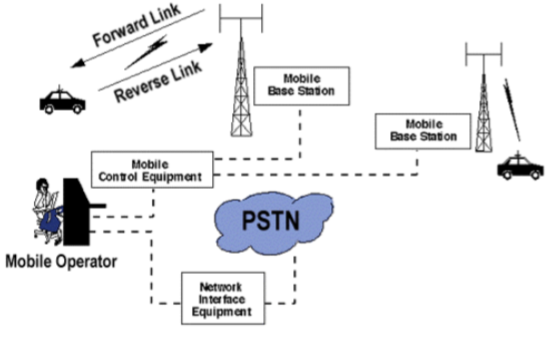 Fig 4 Cellular System Components
Key takeaway
The components of cellular system are PSTN, MSU, MTSO and cell site.
An antenna is a device that radiates equally in all directions. AN isotropic radiator is a small area considered. The gain is given as
DBi= Gain compared to isotropic radiator. It has gain 1db
DBd= gain compared to half wave dipole antenna.
The antenna which is not isotropic is directive. Directivity is
D= Maximum received power/Power received if the antenna was isotropic.
D= Pr(maximum)/Pr(isotropic)
It is covered in section 1.5
In Cellular network, channel allocation schemes are required to allocate bandwidth and communication channels to base stations, access points and terminal equipment.
The objective is to achieve maximum system spectral efficiency in bit/s/Hz/site by means of frequency reuse, but still assure a certain grade of service by avoiding co-channel interference and adjacent channel interference among nearby cells or networks that share the bandwidth.
The basic concept being that a given geography is divided into polygons called cells.
Each cell is allocated a portion of the total frequency spectrum. As users move into a given cell, they are then permitted to utilize the channel allocated to that cell. The virtue of the cellular system is that different cells can use the same channel given that the cells are separated by a minimum distance according to the system propagation characteristics; otherwise, intercellular or cochannel interference occurs.
The minimum distance necessary to reduce cochannel interference is called the reuse distance. The reuse distance is defined as the ratio of the distance, D, between cells that can use the same channel without causing interference and the cell radius, R. Note that R is the distance from the center of a cell to the outermost point of the cell in cases when the cells are not circular.
It means assigning channels or spectrum bands to radio interfaces for communication.
It is process of combining analog and digital signal to send over shared medium.
It divides the capacity of communication channel into multiple channels
Multiplexing is divided into space division, frequency division and time division multiplexing.
Space Division Multiplexing
In wired medium, separate point to point conductors are used to each channel.
In wireless medium multiple elements of antennas are used such that it forms phased array antenna.
Multiple output, multiple input and single input multiple output are the examples of this.
Frequency Division Multiplexing
In these multiple signals are send in distinct frequency in single medium.
The signals are electrical.
Radio, television broadcasting are the examples of FDM.
The service provides can send several channels or signals continuously to all subscribers even the customer has single cable connection.
Time Division Multiplexing
In this for separation of data streams the time is used instead of frequency and space.
It consists of group of bits in sequence one after another.
Each sequence is associated with each receiver.
Carriers sense multiple access and multidrug are the examples of time division multiplexing.
Key takeaway
It is process of combining analog and digital signal to send over shared medium.
It divides the capacity of communication channel into multiple channels
Multiplexing is divided into space division, frequency division and time division multiplexing.
There are two channel assignment strategies in cellular system.
A. Fixed channel assignment:
- In fixed channel assignment each cell is permanently allocated predetermined group of channels. Any call attempt within cell can only be served by unused channels in that particular cell.
- If all channels are occupied, the call is blocked and subscriber does not receive service.
- Borrowing technique where a cell is allowed to borrow channels from a neighbouring cell if all channels are already occupied is always used with this type of strategy. Mobile Base station (MSC) monitors the function of base station including borrowing ensuring that borrowing does not interfere with any call-in progress in donor cell.
B. Dynamic channel assignment:
- In dynamic channel assignment strategy, voice channels are not allocated permanently.
- Entire pool of frequency channels lies with MSC and each time a call request is made, the serving base station requests a channel from the MSC. Switch then allocates a channel to the requested cell following a algorithm.
- MSC allocates frequency channels on dynamic basis if that frequency channel is not presently in use in the cell or any other cell which falls within the minimum restricted distance of frequency reuse to avoid co-channel interference.
- It reduces chances of blocking which increases trunking capacity of system as all available channels are accessible to all cells.
- In this MSC has to collect real time data on channel occupancy, traffic distribution, radio signal strength indication of all channels on continuous basis, thus increasing the computational load on MSC.
Following figure demonstrates the case where a handoff is not made and the signal drops below the minimum acceptable level to keep the channel active. This dropped call event can happen when there is an expansive delay by the MSC in assigning a handoff or when the threshold is set too small for the handoff time in the systems. Excessive delay may occur during high traffic conditions or due to no channels are available on any of the nearby base stations.
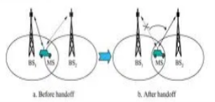
Fig 8 Hand off strategy
In deciding when to handoff, it is important to ensure that the drop in the measured signal is not due to momentary fading and the mobile is actually moving away from the serving base station. But when there is a drop in the measured signal level due to momentary fading and not due to the actual moving mobile away from the base station, that is situation if the handoff of a call takes place then such handoffs must be prevented by ensuring that the base station monitors the signal level for a certain period of time before the handoff is initiated.
Key takeaway
This handoff operation not only involves identifying a new base station, but also requires that the voice and control signals be allocated to channels associated with the new base station.
In this the frequency reuse is increased by reducing number of cells in cluster. The capacity is improved. The CCI is reduced by replacing omni-directional antenna by directional antenna.
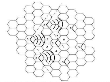
Fig 9 120o sectoring
Key takeaway
It increases number of antennas at BS.
It increases number of handoffs
The free space model is based on assumption that the transmitting and receiving antenna are located in empty environment. The received power Pr in free space is given by
Pr= PtGtGr ( 2
2
GtGr: Transmitter receiver antenna gain
 =wavelength
In db
Pr(dBm) = Pt(dBm)+Gt(dB)-Lp(dB)
Lp(dB) = 20log10(
Key takeaway
Normally free space is used for space communication system and not for cellular telephony.
The unwanted signals which interfere with the actual signal and distort it is called noise. Types of noise is discussed
Internal Noise :-
Also called fundamental noise which is originated within electronic devices or circuits. They are called fundamental sources because they are the integral part of the physical nature of the material used for making electronic components.
This type of noise follows certain rules. Therefore it can be eliminated by properly designing the electronic circuits and equipment.
The fundamental noise sources produce different types of noise. They are as follows.
(i) Thermal noise
(ii) Shot noise
(iii) Partition noise
(iv) Low frequency or flicker noise
(v) High frequency or transit time noise
Shot Noise :- It is produced due to shot effect. Due to the shot effect shot noise is produced in all the amplifying devices rather in all the active devices.
The shot noise is produced due to the random variations in the arrival of electronics (or holes) at the output electrode of an amplifying devices.
Therefore it appears as a randomly varying noise current superimposed and the output. The shot noise “Sounds” like a shower of lead shots falling on a metal sheet.
The shot noise has a uniform spectral density like thermal noise
The mean square shot noise current for a diode is given as
In2 = 2 ( J + Io ) qB Amp2
Where I = direct current across the junction in ampere
Io = reverse saturation current in ampere
q = electron charge = 1.6 X 10⁻¹⁹ C
B = Effective noise Band width in Hz
Thermal Noise :- Also known as Johnson Noise.
The free electrons with in a conductor are always in random motion.
This random motion is due to the thermal energy received by them. The distribution of these free electrons with in a conductor at a given instant of time is not uniform.
It is possible that an excess number of electrons may appear at one end or the other of the conductor
The average voltage resulting from this non uniform distribution is zero but the average power is not zero
As this power results form the thermal energy it is called as the “Thermal noise power”
The average thermal noise power is given by
Pn = KTB Watts
Where k = Boltzmann’s constant = 1.38 X 10⁻²³ J/K
B = Bandwidth of the noise spectrum (Hz)
T = Temperature of the conductor in K
The thermal noise power Pn in proportional to the noise BW and conductor temperature
Flicker noise :- Also known as low frequency noise
The flicker noise appear at frequencies below a few KHz it is sometimes called as 1/f noise in the semiconductor devices, the flicker noise is generated due to the fluctuations in the carrier density.
These fluctuations in the carrier density will cause the fluctuation in the conductivity of the material. This will produce a fluctuating voltage drop when a direct current flows through a device this fluctuating voltage is called as flicker noise voltage.
The mean square value of flicker noise voltage is proportional to the square of direct current flowing through the device.
High frequency noise :- Also called Transit time noise
If the time taken by an electron to travel from the emitter to the collector of a transistor becomes comparable to the period of the signal which is being period of the signal which is being amplified then the transit time effect takes place.
This effect is observed at every high frequency. Due to the transit time effect some of the carriers may diffuse back to the emitter. This gives rise to an input admittance, the conductance component of which increases with frequency.
The minute current induced in the input of the device by the random fluctuations in the output current, will create random noise at high frequencies.
Partition noise :- Partition noise is generated when the current gents divided between two or more paths. It is generated due to the random fluctuations in the division.
Therefore the partition noise in a transistor will be higher than that in a diode.
Noise figure :- It is the ratio of the noise power input to noise power output due to source resistance. The noise figure is a quantity which compares the noise in an actual amplifier with that in an pdeal (noise less) amplifier. Noise figure is expressed in decibels.
Spi (Svi) = Signal power (voltage) input
Npi (Nvi) = noise power (voltage) input due to Rs
Spo (Svo) = Signal power (voltage) output
Npo(Nvo) = noise power (voltage output due to Rs and any noise source within the active device
 Noise figure, NF = 10 log total noise power input
Noise power output due to Rs
 Npo
Npo
 = 10 log
Ap Npi
Where, the power gain of the active devices is
 Ap = Spo
Spi

 Hence, Npo Spi
 = 10 log
Spo Npi

 Spi
Spi
 = 10 log Npi
 Spo
Spo
Npo
The quotient Sp/Np is called the signal to noise power ratio.
The noise figure is the Input signal to noise signal to noise power ratio


 Spi
Spi


 NF = 20 log Npi = 20 Log Svi = 20 log Svo
 Spo Nvi Nvo
Npo
 Where, Sv is called signal to noise Voltage ratio
Nv
Losses
An audio sinusoidal generator Vs with source resistance Rs is connected to the input of Q. The active device is cascaded with a low noise amplifier and filter and the output of this system is measured on a true rms reading voltmeter M. The experimental procedure for determining NF is as follows-
i) Measure Rs and calculate Nvi = Vn
Ii) Adjust the audio signal voltage so that it is 10 times the noise voltage
V/s = 10 Vn or Svi = 10 Nvi
Measure the output voltage with M.
A system is used to measure the noise figure of an active device Q.
Large signal to noise ratio, we may neglect the noise and assume that the voltmeter reading gives the signal output voltage Svo
Iii) Set Vs = O and measure the output voltage Nvo wih M. The low noise amplifier is required only it the noise output of Q is to low to be detected with M.
Friis Formulla :- This formula was named after Danish American Electrical Engineer Harald T. Friis. His formula is used in tele communications engineering to calculate the signal to noise ratio of a multistage amplifier.
He gave two formulars on relates to noise factor while the other relates to noise temperature.
Friis formula is used to calculate the total noise factor of an cascade of stage each with its Owen noise factor and power gain.
The total noise factor can then be used to calculate the total noise figure.
The total noise figure is given as


 Ftotal = F1 + F2-1 + F3-1 + ---------- + Fn-1
G1 G1 G2 G1G2-Gm1
Where Fi and Gi are the noise factor and available power gain respectively of the stage and ‘n’ is the number of stages
Derivation – Let us consider a 3 stage cascaded amplifier that is n=3
A source outputs a signal of power Si and noise of power Ni
Therefore the SNR at input of the chain
 SNRi = Si
Ni
This Si gets amplified by all the 3 amplifiers and the output is given as
So = Si G1 G2 G
Using the definition of the Noise factors of the amplifiers we get the final result


 Ftotal = 1+ Na1 + Na2 + Na3
NiG1 NiG1G2 NiG1G2G3

 = F1 = F2-1 = F3-1
G1 G1G2

 Ftotal = F1 = F2-1 = F3-1
G1 G1G2
Note – Friis formula for noise temperature is given as

 Teq = T1 + T2 + T3 + ------
G1 G1G2
Key takeaway
The noise power at the output of the chain consist of following 4 parts
i) Amplified noise i.e. Ni G1 G2 G3
Ii) The output noise of first amplifier Na1 which gets further amplified by 2nd and 3rd amplifier i.e. Na1 G2 G3
Iii) Similarly output noise of 2nd amplifier Na2 amplified by 3rd i.e. Na2 G3
Iv) Output noise of 3rd amplifier Na3
Therefore, the total noise power at the output equals
No = NiG1G2G3 + Na1G2G3 + Na2G3 + Na3
And the NSR at output becomes
 SNRo = SiG1G2G3
NiG1G2G3+Na1G2G3+Na2G3+Na3
The Total noise factor or noise figure may now be calculated as

 Ftotal = SNRi = Si
 SNRo Ni
 SiG1G2G3
NiG1G2G3+Na1G2G3+Na2G3+Na3


 = 1+ Na1 + Na2 + Na3
NiG1 NiG1G2 NiG1G2G3
Numerical :-
1) A noise generator using diode is required to produce 15µV noise voltage in a receiver which has an input impedance of 75Ω (Purely resistive) . The receiver has a noise power bandwidth of 200KHz calculate the current through the diode.
Sol- Given Vn = 15µV
R = 75Ω
B = 200 KHz
Noise current flowing through 75Ω is
 In = Vn = 15X10-6
R
= 0.2X10-6
= 0.2µa
Diode current –short noise current is given by
In2 = 2 (I +Io) qB
In2 = 2I X Q X B (neglecting Io)
(0.2 X 10⁻⁶) 2 = 2I X 1.6 X 10-19 X 200 X 103
I = 0.625 A = 625 µA
2. A receiver has a noise power band width of 12KHz. A register which watch with the receiver input impedance is connected across the antenna terminals what is the noise power contributed by this register in the receiver bandwidth. Assume temperature to be 30ºC
Sol – Given : B = KHz ; T = 30ºC = 30+ 273 = 303 K
Pn = KTB
= 1.38 X 10-23 X 303 X 12 X 103
= 5.01768 X 10⁻¹⁷ W
- Multi path causes large and rapid fluctuations in a signal
- These fluctuations are not the same as the propagation path loss.
Multipath causes three major things in wireless communication
- Rapid changes in signal strength over a short distance or time.
- Random frequency modulation due to Doppler Shifts on different multipath signals.
- Time dispersion caused by multipath delays
- These are called “fading effects
- Multipath propagation results in small-scale fading.
When the signal is transmitted there are many obstructions in the path due to which the power of the signal fluctuates and the received power is the fluctuated value. The power fluctuations are due to multipath fading. The receiver power is the mean power given as

The probability density is
Fp( =
=  exp {-
 ln2(
ln2( }
}
 = logarithmic standard deviation
The above method is called large area shadowing.
Key takeaway
The shadowing can be managed by proper frequency planning and adaptive transmit power control
Reference:
1. T.S. Rappaport, “Wireless Communication-Principles and practice”, Pearson
Publications, Second Edition.
2. Misra, Wireless Communication & Network: 3G & Beyond, McGraw Hill Education
3. Jaganathan, Principles of Modern Wireless Communication System, McGraw Hill Education
4. Upena Dalal, “Wireless Communication and Networks”, Oxford Press Publications.
5. T L Singal, “Wireless Communications”, McGraw Hill Education.