Unit-4
Multiplexing and Multiple Access
4.1.1 FDMA
- It sub-divide frequency into a several frequency band with non-overlapping.
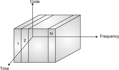
Fig. 1 FDMA
- FDMA allows user to transmit signals simultaneously to satellite transponder with the help of assigning a specific frequency to every user among a channel.
- Each transaction of signal has own unique radio channel. Channel are probably 30 KHz or less used to transmit or receive channels.
- Frequency allocation made by national policies. Uplink (i.e. from mobile station to base station). Downlink (i.e. from base station to mobile station) uses frequencies bands like. Uplink and downlink with frequencies mentioned below :
Uplink | 890.2 MHz, 915 MHz |
Downlink | 935.2 MHz to 960 MHz |
Uplink (UL) and downlink (DL) can be described with the help of one relation among them as follows:
fd = fu + 45 MHz
- For Example :
If UL frequency is :
fu = 890 MHz + n∙ 0. 2 MHz
Then
fd = 935 MHz + n ∙ 0. 2 MHz
- Fixed assigned frequency makes scheme very inflexible limits to no. Of sender turn into disadvantage of FDMA.
4.1.2 TDMA
- It is based on time slots. TDMA more flexible than FDMA scheme.
- Dynamic allocation of channel or by some fixed pattern channels get allotted for time slots to takes places synchronized communication.
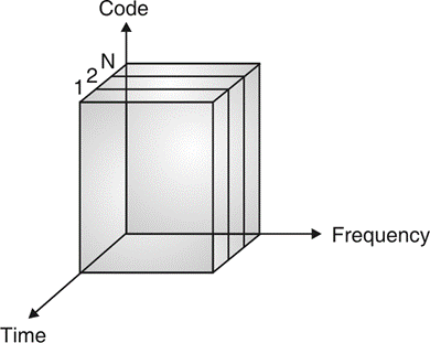
Fig. 2 TDMA
- Fixed channel are allocated for communication as best practice solution for wireless phone system in Medium Access Control (MAC) reserved time slot access is for crucial.
4.1.3 CDMA
- CDMA stands for Code Division Multiple Access. CDMA is a technique for spread spectrum multiple access.
- Data signals are XOReD with pseudorandom code and then transmitted over a channel.
- Different codes are used to modulate their signals, selection of code to modulate is important aspect as it relates with performance of system.
- In CDMA, single channel uses entire bandwidth and it does not share time as all stations transmit data simultaneously. Due to this CDMA differ from FDMA and TDMA.
- Let us assume we have 4 different stations A, B, C and D. All 4 stations connected to same channel. Data from station A is d1, B is d2, C is d3 and D is d4 similarly code assigned to A is C1, B is C2, C is C3 and D is C4.
- To transmit data, all 4 stations have multiplication strategy i.e. either code multiply by itself. It results in 4 stations or code multiply results in 4 stations or code multiply results in 4 station of code multiply by another, it results in zero station.
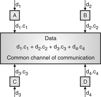
Fig. 3: Communication of station with code
- If station C and station D are talking to each other, D wants to listen whatever C is saying. It multiplies data on channel by C3 of station C.
- As C3 C3 is 4 and rest of combination i.e. C1 C3, C2 C3 and C4 C3 are all zero.
- Every station has some code, which is sequence of numbers known as chips.
- Sequence should be selected in proper manner to get appropriate codes. Orthogonal sequence has some properties :
- Multiplication of sequence by a scalar.
- Inner product of two equal sequences.
- Inner product of two different sequences.
- Sequence generation uses Walsh table to generate chip sequence.
Key takeaway
Approach | SDMA | TDMA | FDMA | CDMA |
Idea | Segment space into cells/sectors | Segment sending time into disjoint time-slots, demand driven or fixed patters | Segment the frequency band into disjoint sub-bands | Spread the spectrum using orthogonal codes
|
Terminals | Only one terminal can be active in one cell/one sector | All terminals are active for short periods of time on the same frequency | Every terminal has its own frequency. Uninterrupted | All terminals can be active at the same place at the same moment uninterrupted. |
Signal separation | Cell structure, directed antennas | Synchronization in the time domain | Filtering in the frequency domain | Code plus special receivers |
Advantages | Very simple, increases capacity per km2 | Established, fully digital, flexible | Simple, established robust | Flexible, less frequency planning needed, soft handover |
Disadvantages | Inflexible, antennas typically fixed | Guard space needed (multipath propagation), synchronization difficult | Inflexible, frequencies are a scarce resource | Complex receivers, needs more complicated power control for senders |
Comment | Only in combination with TDMA, FDMA or CDMA useful | Standard in fixed networks, together with FDMA/SDMA used in many mobile networks | Typically combined with TDMA (frequency hopping patterns) and SDMA (frequency reuse) | Still faces some problems, higher complexity, lowered expectations: will be integrated with TDMA/FDMA |
4.1.4 OFDMA
It is orthogonal frequency division multiplexing. It has multiple closely spaced carriers and due to the orthogonality between them mutual interference is avoided. It is most commonly used form of MCM. The symbols which are to be transmitted are paralyzed after they are modulated. They under go inverse FFT operation producing OFDM symbols. At the receiving end there has to be an FFT operation to retrieve the symbols in frequency domain. The main difference in OFDM and OFDMA is that in OFDM the user is allocated only on time domain but in OFDMA the user is allocated both in time as well as frequency domain.
4.1.5 SC-FDMA
It is single carrier FDMA. It has lower peak to average power ratio unlike OFDMA and hence can be used in uplink. In this scheme the symbols are first pre coded with DFT and then IFFT. Here the ISI is reduced as all subcarriers on a period of time represent same symbol.
Key takeaway
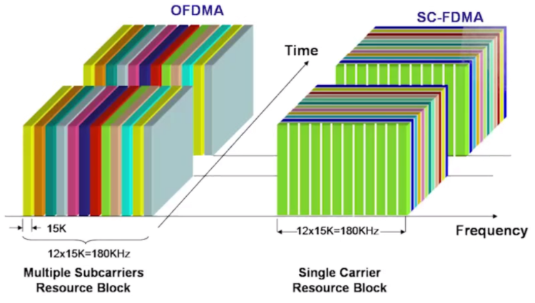
Fig 4 OFDMA and SC-FDMA
This scheme overcomes the problems in CDMA. It is Interleave Division Multiple Access. The user-specific interleavers having low cross-correlation amongst them. The interleaved data resulted from user-specific interleavers, demonstrates better orthogonality amongst each other in the channel. The condition of orthogonality is maintained for reducing the risk of collision amongst the interleavers during communication process. In IDMA inter leavers as the only means in order to distinguish the users. Historical point of view, interleaving was employed in ordering block storage on disk-based storage devices including floppy disk and the hard disk systems. The primary preference of interleaving was to adjust the timing differences between the adjacent bits during data transmission between computer and storage media.
Key takeaway
It removes ISI. It has low receiver cost. It has increased diversity against fading.
- Transmitted signal is received at receiver as time delayed multiple versions of transmitted signal due to propagation delay. RAKE receiver combines all multipath components of original transmitted signal in order to improve signal to noise ratio at receiver. It provides separate correlation receivers for each multipath component to combine all multipath components.
- RAKE receiver is diversity receiver designed for CDMA, where the diversity is provided by the fact that the multipath components are practically uncorrelated from one another when their relative propagation delays exceed a chip period.
- A RAKE receiver utilizes multiple correlators to separately detect the M strongest multipath components. The outputs of each correlator are weighted to provide a better estimate of the transmitted signal than is provided by a single component. Demodulation and bit decision is based on weighted outputs of the M correlators.
- Basic idea of RAKE receiver was proposed by Price and Green. In outdoor environments, the delay between multipath components is usually large and, if the chip rate is properly selected the low auto correlation properties of CDMA spreading sequence can assure that multipath components will appear nearly uncorrelated with each other.
- If only one correlator is used the receiver, once the output of the single correlator is corrupted by fading, the receiver cannot correct the value. Bit decision based on only a single correlation may produce a large bit error rate. In RAKE receiver, if the output from one correlator is corrupted by fading, other signals can be used to recover the original signal and corrupted signal is not counted through weighing process. Decision based on the combination of the M separate decision statistics offered by the RAKE provides a form of diversity which can overcome fading and thus improve CDMA reception.
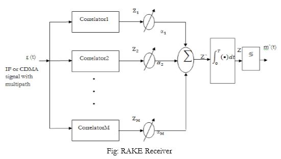
Fig 5 Rake Receiver
- The M decision statistics are weighted to form an overall decision statistic as shown in above figure. The outputs of the M correlators are denoted by Z1, Z2, ... And ZM.
- They are weighted by α1, α2, ……… and αM respectively.
- The weighting coefficients are based on the power or the SNR from each correlator output. If the power or SNR is small out of a particular correlator, it will be assigned a small weighting factor. In case of a maximal ratio combining diversity scheme, the overall signal Z is given by,

The weighting coefficients are normalized to the output signal power of the correlator in such a way that coefficients sum to unity.

Choosing weighting coefficient based on actual outputs of correlators yields good RAKE performance.
Key takeaway
RAKE receiver is diversity receiver designed for CDMA, where the diversity is provided by the fact that the multipath components are practically uncorrelated from one another when their relative propagation delays exceed a chip period.
4.4.1 Pure ALOHA

Fig.6: Classical ALOHA
- Above random access scheme no central control access, no any co-ordination occur in stations.
- When more than two stations are accessing medium, collision take places.
4.4.2 Slotted ALOHA
- It is refinement of classical aloha scheme. All senders are synchronized and transmission takes place at beginning of time slot.
- It provided time slots additionally to classical aloha so known as slotted aloha.
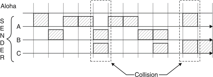
Fig.7: Slotted ALOHA
4.4.3 CSMA and their versions
- Carrier Sense Multiple Access also known as CSMA.
- A sense is added before any channel get access to medium. As request occurred to an idle carrier, probability of collision becomes negligible.
- Different version of CSMA are as :
- Non-persistent CSMA
- 1-Persistent CSMA
- P-Persistent CSMA

Fig 8: CSMA with collision detection
Packet reservation multiple access is a plan where which has frames with fixed number of slots. If there is any data packet in a terminal, they have to compete to gain access in any free slot. Ones the packet reaches base station it needs reservation in the next slot frame. In PRMA the adjacent cells make use of different carrier frequencies in line with cellular reuse plan.
In PRMA the time frame is occupied only during the speech talks and it leaves the channel during the silent periods. It can be used for multi rate data traffic as it is flexible to receive various traffic bit rates.
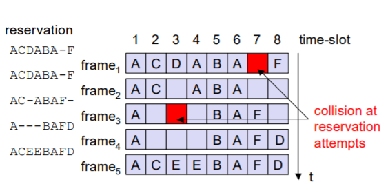
Fig 9: PRMA Scheme
There is minimal intervention from the base station it requires minimum central control. The active voice terminal drops its reservation when moves into other cells and due to this it has to re-contend with other terminals to broadcast the remaining voice packets.
Polling is nothing but a scheme in which the base station sends ready signals to all mobile terminals. The terminals which are ready transmit their random numbers using CDMA or FDMA. This happens without collision. The base station will select one address for polling from all the random numbers which it receives. The base station acknowledges correct packet and polls it to the next terminal. This cycle continues.
Key takeaway
PRMA can be used in combination with CDMA based systems. It is ideal for multimedia traffic.
Reference:
1. T.S. Rappaport, “Wireless Communication-Principles and practice”, Pearson
Publications, Second Edition.
2. Misra, Wireless Communication & Network: 3G & Beyond, McGraw Hill Education
3. Jaganathan, Principles of Modern Wireless Communication System, McGraw Hill Education
4. Upena Dalal, “Wireless Communication and Networks”, Oxford Press Publications.
5. T L Singal, “Wireless Communications”, McGraw Hill Education.