Unit – 1
Node and mesh analysis
Nodal analysis
In the nodal method we are finding the node voltages with the following steps:
- Select a reference node. Assign all the rest nodes voltages, with respect to reference node.
- Use Kirchhoff’s and Ohm’s Laws to each non-reference node and branch currents.
- Resolve the system of equations and obtain node voltages.
Consider the following circuit.
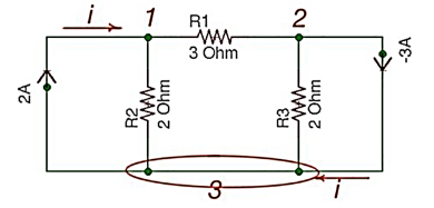
Let us consider a reference node – 3.
In a real circuit a reference node is ground is assumed to have potential.
By the Kirchhoff’s Law having the following current relation:
I1 = i1 + i2
I2 = i2 -i3
Let us represent currents like ratio of voltage and resistance by the Ohm’s Law:
i 1 = v1 /R1 ; i 2 = v1 -v2 /R2 ; i3 = v2/R3;
Or
i 1= v1 * G1 ; i2 =(v1 -v2)*G2 ; i3 =v2 * G3
i1 = v1 * G1 + (v1-v2) * G2 ;
i2 = (v1-v2) * G2 – v2 * G3
i1= v1 * (G1 +G2) – v2 * G2
i2 = v1 *G2 – v2 *(G3 +G2)
Or
And we achieve the following matrix equation, which can be resolved by the Cramer’s rule:
[ G1 + G2 -G3 -G3 ] [v1] = [I1]
[ G2 -G2][v2] =[I2]
Consider the following figure :

There are two possibilities that exist:
- If the voltage source is between reference node and non-reference node, the non-reference voltage is considered equal to the voltage source.
- If the voltage source is between two non-reference nodes, these two nodes are generalised nodes. To determine its voltage Kirchhoff’s Laws must be applied.
Applying Kirchhoff’s Law we achieve the following equations:
i 1 + i4 = i2 + i3
-v2 +5+v3 =0
v 1 =10
By Ohm’s Law
These equations will help determine node voltages.
Mesh Analysis
Mesh analysis is applicable to the networks which are planar. Planar network is a network where branches are not passing over or under each other.
Nodal method uses Kirchhoff’s currents Law to consider nodal voltages, and Mesh method uses Kirchhoff’s voltages Law to consider mesh currents. Mesh is a loop, which does not contain any other loops.

There are only two meshes in abefa and bcdeb, abcdefa is not a mesh but a loop However, for Mesh method only meshes are in use.
Mesh analysis steps are the following:
- Assign mesh currents to all the meshes in a circuit.
- Apply Kirchhoff’s voltage Law to each mesh. Apply Ohm’s Law to determine voltages with mesh currents.
- To resolve simultaneously all the equations to consider mesh currents.
The following equations correspond to the Kirchhoff’s Voltage Laws for the meshes:
V1 = i1 *(R1+R3) – i2 *R3
-V2 = -i1 *R3 + i2 * (R3 +R2);
[ R1 +R3 -R3 [i1]= [V1]
-R3 R2+R3] [i2] = [V2]
Using Cramer’s formula for resolving the matrix equations above we can find mesh currents.
I1 =i 1 I2 = i2 I1 -I2 =i3
Example
Q1) Find the current flowing through 20 Ω resistor of the following circuit using Nodal analysis.

Step 1 − There are three principle nodes in the above circuit. Those are labelled as 1, 2, and 3 in the following figure. In the above figure, consider node 3 as reference node (Ground).

Step 2 − The node voltages, V1 and V2, are labelled in the following figure.

Step 3 – There are two nodal equations, since there are two principal nodes, 1 and 2, other than Ground.
The nodal equation at node 1 is
V1 -20/5 + V1/10 + V1-V2/10 =0
2V1 -40 +V1+V1-V2/10 =0
4V1 -40-V2 =0 --- V2 = 4V1-40 -------(1)
The nodal equation at node 2 is
-4 +V2/20 + V2-V1/10 =0
-80 + V2 + 2 V2 – 2V2/ 20 =0
= 3V2 -2V1 =80 --------------(2)
Step 4 − Finding node voltages, V1 and V2 by solving Equation 1 and Equation 2.
Substitute Equation 1 in Equation 2.
3(4V1−40)−2V1=80
⇒12V1−120−2V1=80
⇒10V1=200
⇒V1=20V
Substitute V1 = 20 V in Equation1.
V2=4(20)−40
⇒V2=40V
So, we got the node voltages V1 and V2 as 20 V and 40 V respectively.
Step 5 − The voltage across 20 Ω resistor is nothing but the node voltage V2 and it is equal to 40 V. Now, we can find the current flowing through 20 Ω resistor by using Ohm’s law.
I 20Ω = V2/R
Substitute the values of V2 and R
I 20 Ω = 40/20
I 20Ω = 2A
Therefore, the current flowing through the 20Ω resistor is 2A.
Q) Find the voltage across 30 Ω resistor using Mesh analysis.

Step 1 − There are two meshes in the above circuit. The mesh currents I1 and I2 are considered in clockwise direction. These mesh currents are shown in the following figure.

Step 2 − The mesh current I1 flows through 20 V voltage source and 5 Ω resistor. Similarly, the mesh current I2 flows through 30 Ω resistor and -80 V voltage source. But, the difference of two mesh currents, I1 and I2, flows through 10 Ω resistor, since it is the common branch of two meshes.
Step 3 − Since there are two meshes in the given circuit write the mesh equations, assume the mesh current of that particular mesh as greater than all other mesh currents of the circuit.
The mesh equation of first mesh is
20−5I1−10(I1−I2)=0
⇒20−15I1+10I2=0
⇒10I2=15I1−20
Divide the above equation with 5.
2I2=3I1−4
Multiply the above equation with 2.
4I2=6I1−8-----------------(1)
The mesh equation of second mesh is
−10(I2−I1)−30 I2+80=0
Divide the above equation with 10.
−(I2−I1)−3I2+8=0
⇒−4I2+I1+8=0-----------------(2)
4I2 = I1 +8
Step 4 − Finding mesh currents I1 and I2 by solving Equation 1 and Equation 2.
The left-hand side terms of Equation 1 and Equation 2 are the same. Hence, equate the right-hand side terms of Equation 1 and Equation 2 in order find the value of I1.
6I1 -8 = I1 +8
5I1 =16
I1 = 16/5 A
Hence, 4I2 = 16/5 + 8
4I2 = 56/5
I2 = 56/20 = 2.8 A
Step 5 − The current flowing through 30 Ω resistor is nothing but the mesh current I2 and it is equal to 14/5 A. The voltage across 30 Ω resistor by using Ohm’s law.
V 30 Ω = I2 R
V30Ω = (14/5) x 30 = 84V
Concept of Super nodes
We are primarily interested in node voltages. We may avoid utilizing the voltage source branch that is causing difficulty. To do this we may treat N2, N3 and the voltage source together as a type of super node and apply KCL to both nodes at same time.
This is possible since total current leaving node 2 is zero and total current leaving node 3 is also zero. Thus, the current leaving both the nodes in totality must be zero.

Fig 1 Circuit with super node
A simple way of identifying the super node is to think of the voltage source as a short circuit physically joining the two nodes together.
Solving the above circuit for finding node voltage
KCL for V1
2+5+ [(V1-V2)/(1/3)]+[(V1-V3)(1/2)]=0
5V1 -3V2-2V3+7=0 (1)
KCL at V4
-5+6+ [(V4-V2)/(1/4)]+[(V4-V3)/1] = 0
4V2+V3+4V4+1=0 (2)
Applying KCL for both N2 and N3 simultaneously we get
[(V2-V1)/(1/3)]-2+(4V2)+[2(V3-V1)]+V3-6=0
-5V1 + 7V2 + 3V3 = 8 (3)
We get one more relation as
V3-V2 = 4 (4)
Solving equations 1,2,3 and 4 we get
V2= -3/5 V
V3 = 17/5 V
V1= -2/5 V
Concept of Super mesh
If the current source is also present in the network than we face difficulty in writing mesh equations. A better approach is we assume the current source to be open circuited and create a new mesh called super mesh. We than apply KVL only to those meshes in the modified network.

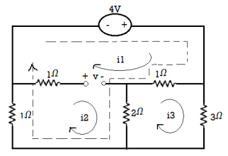
Fig 2 Ciruit (a) 3A in circuit circuit (b) with super mesh
Let the mesh current be i1, i2 and i3. The current source be mentally open circuited. Thus, creating a new mesh called super mesh shown by dotted lines. Applying KVL around this mesh we get
-4+ (i1-i3)1 + 2(i2-i3)+i2 = 0
i1+3i2-3i3=4 (1)
2(i3-i2)+i3-i1+3i3=0
i1+2i2-6i3=0 (2)
i1-i2=3 (3)
Solving above equations we get
i1= 4A
i2= 1A
i3= 1A
Key takeaway
When a current source creates problem while applying mesh we use super mesh by open circuiting the current source. When a voltage source creates problem while applying node we use super node by short circuiting the voltage source.
Matrix Analysis of Networks
When we solve circuit problems, we need to write the equations corresponding to the Ohm’s Law and the Kirchoff’s Laws. These same equations need to be used even when there are a large number of branches, and as such when using Matrix analysis of networks.
Kirchoff’s current Law in matrix form Let Ij be the current in the jth branch. Consider any node k in the network, as shown in the figure. The jth branch may either be directed away from kth node, may be directed towards kth node, or may not be incident on the kth node. From Kirchoff’s current Law,

-i1-i2-i4+i6+i7=0
i1 + i2 + i4 = i6 + i7
Branch currents directed away from the node are associated with a coefficient of +1, while current directed towards the node are associated with a coefficient –1. Branches not connected to (or incident on) the node are obviously associated with a coefficient of 0. These coefficients are defined as ajk so that Kirchoff’s current law may thus be written as

Or for kth node we can write

The collection of such equations for each node k would give the matrix equation

In the matrix [A]t, the row vectors are dependant, since their sum is zero. For this reason, the matrix [A]t is written with one row less, usually the last row for convenience, so that there are only (n-1) rows.
The matrix [A]t of dimension (n-1)×b is referred to as the node-branch incidence matrix. The matrix [A] of dimension b× (n-1) is then referred to as the branch-node incidence matrix. The elements of the matrix [A] are
ajk = +1 if jth current is directed away from the kth node
ajk = −1 if jth current is directed towards the kth node
ajk = 0 if jth current is not incident on the kth node
Kirchoff’s voltage Law in matrix form
Similarly, the Kirchoff’s voltage law may be applied for the sth loop. The coefficients brs of the voltages are defined as +1, −1 or 0 depending on whether the loop direction is the same as the branch direction or not.
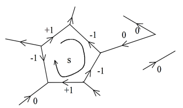
For sth node, for all s;

Where brs = −1, 0, or +1
In matrix form this becomes

The matrix [B]t of dimension l×b is referred to as the mesh-branch incidence matrix. The matrix [B] of dimension b×l is then referred to as the branch-mesh incidence matrix. The elements of the matrix [B] are
The elements of the matrix [B] are brs = +1 if rth current is in the same direction as the sth loop
brs = −1 if rth current is in the opposite direction to the sth loop
brs = 0 if rth current is in the not part of the sth loop
Ohm’s Law in matrix form
A general branch may contain a voltage source and/or a current source in addition to the branch impedance/admittance.
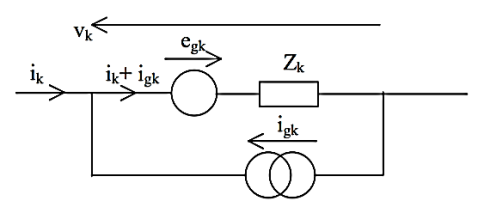
Applying Ohm’s Law
vk = - egk + Zk igk + Zk ik for all branches k = 1, 2, .... ... b
However, using Thevenin’s Theorem or Norton’s Theorem, a current generator may be converted to a voltage generator or vice versa, except when ideal. Thus, analysis can be done with only either a voltage source or a current source. Thus, we may either write
vk = - egk + Zk ik for all branches k = 1, 2, .... ... b

Which may be written in matrix form as

Or we may write vk = Zk igk + Zk ik or Yk vk = Yk Zk igk + Yk Zk ik i.e. ik = Yk vk - igk
Or in matrix form as

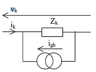
Where:

Mesh Analysis
In mesh analysis, we eliminate the branch voltages from the equations. We further reduce the number of remaining currents to the minimum using Kirchoff’s current law and apply Kirchoff’s voltage law for solution. Let us define a set of mesh currents, Im
The branch currents Ib can be seen to be related to the mesh currents Im by an algebraic summation. In fact, if an example is considered, it will be easily seen that the relation corresponds to the matrix [B].

We can eliminate Vb from the equations, by pre-multiplying equation by [B]t

It is seen that [B]tVb = 0 Also Ib = [B] Im

[B]t Vb = 0 corresponds to the sum of the voltages around a loop is zero. [B]t Vb must correspond to the sum of the voltages around a loop. Since [B]t is constant, and Egb is the branch source voltage vector, [B]t Egb must correspond to the sum of the source voltages around a loop. This is defined as the mesh source voltage vector


This corresponds to only l equations, and the only unknowns in that equation is Im which corresponds to l unknowns. Thus, the original problem of 2b equations and 2b unknowns has been reduced to that of l equations and l unknowns. The elements of the matrix [Zm] can be obtained either by going through the above mathematical considerations, or by inspection in the following manner for the simple problems.
zjj = self impedance of mesh
j = sum of all branch impedances in mesh j
zjk = mutual impedance between mesh j and mesh k
= sum of all branch impedances common to mesh j and mesh k and traversed in mesh direction − sum of all branch impedances common to mesh j and mesh k and traversed in opposite direction ej = algebraic sum of the branch voltage sources in mesh j in mesh direction.
Note: Matrix [B] is also known as the tie-set matrix (as its elements tie the loop together).
Key takeaway
From Kirchoff’s Laws we have


And from Ohm’s Law


Thus, the total number of independent equations is n – 1 + l + b = b + b = 2 b It is seen that there is a total of 2b independent equations and 2b unknowns (corresponding to b branch currents and b branch voltages). However, it is not usual to solve the equations for both current and voltage simultaneously.
So let us see how these may be reduced for solution. The reductions can be done in one of two ways. The first is to eliminate the voltages and solve for currents. The second method is to eliminate the currents and solve for the voltages. These two methods are known as mesh analysis and nodal analysis respectively.
Examples
Q1) Solve the circuit using Mesh matrix analysis. Work from first principles.

A1) Let us first number the branches and the loops.

Let us write the loop currents in terms of the branch currents.
i1 = I1
i2 = - I3
i3 = I1 – I2
i4 = I2
i5 = I2 – I3
i6 = I3
Or in matrix form we can write it as

This gives us the [B] matrix or the Branch-Mesh incidence matrix. We can also write the Mesh–Branch incidence matrix [B]t matrix as follows, independent of the above, by writing the relation between the mesh direction and the branch direction.

The vector of branch currents Egb can be written as follows.

We now need to write the branch impedance matrix. Then we can write expressions for the mesh voltage vector and the mesh impedance matrix using the derived equations.
Egm = [B]t Egb , and [Zm] = [B]t [Zb] [B]
The Branch impedance matrix is 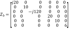
Thus we can write the mesh source voltage vector

This could also have been written by inspection by writing down the sources effectively driving the mesh currents round the loops. If first principles is not asked for, writing by inspection would generally be sufficient. The mesh impedance matrix can be written as


This matrix too could have been written by inspection, and would normally have been done that way, if first principles were not required. Thus, we may now write the mesh analysis equation as

The equations may be solved by inversion or otherwise.


The discriminant ∆ is given by


Thus, I1 is given as


Currents I2 and I3 can be similarly determined. The branch currents i1, i2, ..... May then be determined from the matrix equation.
Nodal Analysis
In nodal analysis, we eliminate the branch currents from the equations. We further reduce the number of remaining voltages to the minimum using Kirchoff’s voltage law and apply Kirchoff’s current law for solution. Let us define a set of nodal voltages, VN which are node pair voltages (i.e. voltage across a pair of nodes) The branch voltages Vb can be seen to be related to the nodal voltages VN by an algebraic summation. In fact, if an example is considered, it will be easily seen that the relation corresponds to the matrix [A].

This gives

But, [A]t Ib = 0.


Where:
 and
and 
As in the case of mesh analysis, the source nodal current vector IgN and the nodal admittance matrix [YN] could be written by inspection as follows.
yii = sum of all branch admittances incident at node i
yij = negative of the sum of all branch admittances connecting node i and nodej.
The reason why the negative sign appears can be understood as follows. Consider the simple circuit shown.
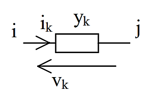
ik = yk vk = yk (Vi – Vj)
At any node i, from Kirchoff’s current law, nodal injected current at the node i is equal to the sum of the branch currents going out from the node

Also,

At node i for all j (different k actually correspond to different j)

Since Vi is a constant for a given i,


Thus, we see that the final equation derived in this manner actually corresponds to the nodal equation, and that the diagonal term of the matrix actually corresponds to the branch admittances connected to the node, and that the off diagonal terms actually correspond to the negative of the branch admittance.
As in the case of mesh analysis, the nodal equation IgN = [YN]VN is first solved to give VN and the branch voltages and branch currents can then be obtained using the matrix equations.
Example
Q1) Solve the circuit using Mesh matrix analysis. Work from first principles.

A1) Let us first convert the above circuit with current sources. The network may also be drawn in terms of admittances as follows.

The branch-node incidence matrix [A], branch injected current Igb, and the branch admittance matrix may be written, with the reference selected as the earthed node as


As in the case of mesh analysis, the nodal current injection vector and the nodal admittance matrix may be written from first principles.


The branch current will be


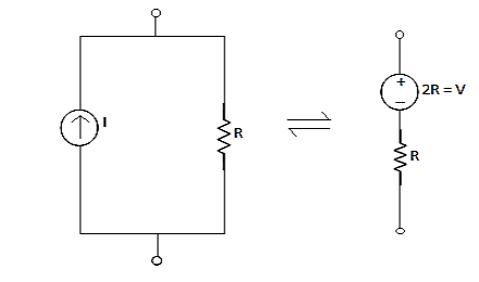
Source transformation
Source transformation methods are used for circuit simplification to modify the complex circuits by transforming independent current sources into independent voltage sources and vice-versa.
Conversion of Voltage Source to Current Source
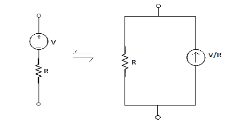
Conversion of Current Source to Voltage Source
Examples
Q1) Find the output voltage using source transformation technique. For the given circuit?

A1) The 12 V Voltage source transfers into Current source:
I =12/3 =4 mA
After source transformation the circuit will be
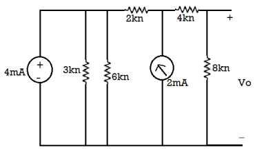
The 3KΩ and 6 KΩ are parallel to each other so equivalent resistance = (3x6)/(3+6) = 2k
The equivalent circuit will now be

The 4mA current source transfers voltage of =4x2 =8V
The reduced circuit diagram is
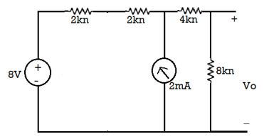
Now 2k and 2k are in series
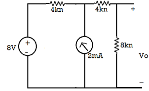
The 8V voltage source convert into current source: = 8/4 = 2A
The circuit diagram is
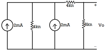
The both current source are in same direction so add the both current sources.

The 4mA current source transfer into a voltage source: = 4 × 4 = 16 V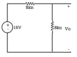
So, calculate the output voltage across 8 ohm using voltage divider rule:
𝑉0 = 16 × 8/(8 + 8) = 8 V
Duality
The two networks are said to be dual if mesh equation of one network is equal to node equation of other.
Let us consider RLC circuit
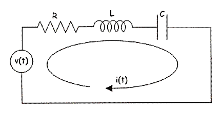
Fig 5 RLC Circuit
Applying KVL we have
v(t) = ri(t) + L  +
+ 
So, dual of above network will be
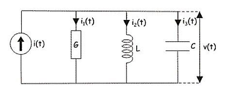
Fig 5 Dual of RLC circuit
i(t) = Gv(t) + C  +
+ 
Steps for construction of Dual Network:
i) In each loop place a dot. This internal dot corresponds to independent node in the dual network.
Ii) Outside network place a dot. This is called datum node is dual network
Iii) Connect all the adjacent loops by dashed lines crossing common branches.
Iv) In dual network this common branch is replaced by its dual element.
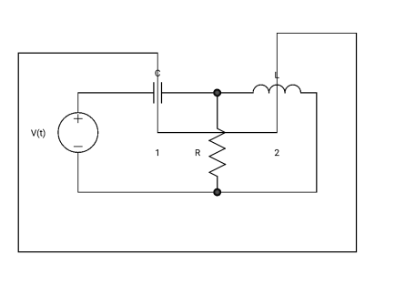
Fig 7 Circuit whose dual is to made
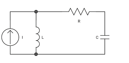
Fig 8 Dual of above circuit
Example
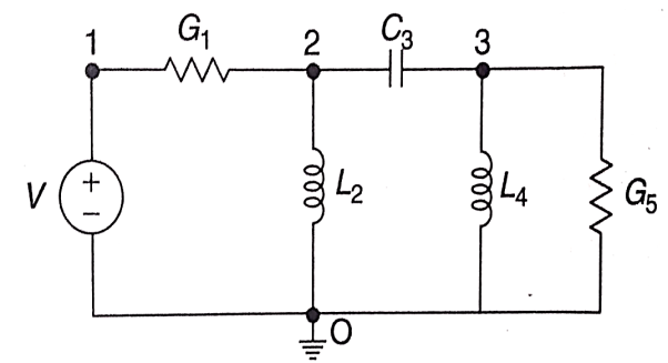
Q1) Draw the dual of the network shown in figure
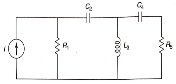
A1) For drawing the dual network, mark the node and dashed lines

The dual network is shown in figure
Key takeaway
Some important duals are given below.
Loop | Node | Loop | Node |
Current | Voltage | Number of Loops | Number of nodes |
Inductance | Capacitance | Link | Tree branch |
Resistance | Conductance | Link current | Tree branch voltage |
Branch Current | Node Voltage | Tree branch current | Link voltage |
Mesh or Loop | Node or pair | Tie Set | Cut Set |
Loop Current | Node pair Voltage | Short Circuit | Open Circuit |
Mesh Current | Node Potential | Parallel path | Series path |
|
|
|
|
Solved Examples
Q1. For the circuits given below write the voltage equations:
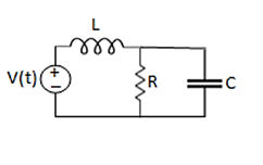
Solution: Let current i1be in loop 1 current and i2 for loop 2 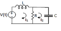


Que Write the loop equations for the given circuit below?
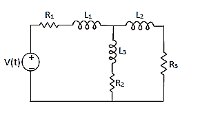
Solution:
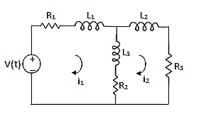
For loop 1

For loop 2

Example: Using nodal analysis find voltage across 5resistor.
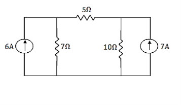
Solution:
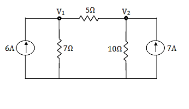
For V1


For V2


Solving 1 and 2:


For 5 voltage = 
= -50.9 + 57.27
= 6.37V
Q) Find the node voltage in the network shown in figure.

A) The node voltage V1 is

Applying KCL at node 2,


Nodes 3 and 4 will form a super node. The voltage equation for the super node.


Solving above equation for given node voltages we get
V1 = -12V
V2 = -4V
V3 = 0
V4 = -2V
Q) For the circuit shown in figure, Find the voltage across 4Ω resistor by using nodal analysis.
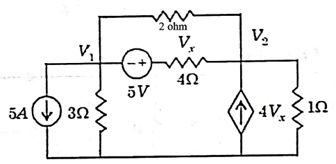
A) Let the voltage at node 1 and 2 be V1 and V2.


Now applying KCL at node 1


Applying KCL at node 2 we get


Solving


Again we have the following set of equations


Again we have


The value Vx will be

Q) Draw the dual of the network shown in figure
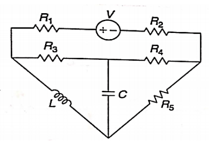
A) For drawing the dual network, mark the node and dashed lines

The dual network is shown in figure

Q) Find dual for the series RLC circuit?
Sol: Let us consider RLC circuit

Applying KVL we have
v(t) = ri(t) + L  +
+ 
So, dual of above network will be
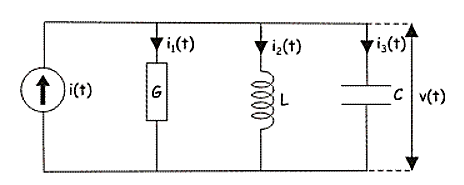
i(t) = Gv(t) + C  +
+ 
Q) For the characteristics given below comment about the type of element?

Sol: It is Linear, Bilateral and Passive element
Q) For the figure below comment on the type of element?
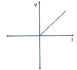
Sol: The element is Non-Linear, Passive and Unilateral.
References:
1. Franklin F. Kuo, “Network Analysis and Synthesis,” Wiley India Education, 2nd Ed., 2006.
2. Van, Valkenburg, “Network analysis,” Pearson, 2019.
3. Sudhakar, A., Shyammohan, S. P., “Circuits and Network,” Tata McGraw-Hill New
Delhi, 1994.
4. A William Hayt, “Engineering Circuit Analysis,” 8th Edition, McGraw-Hill Education.
5. A. Anand Kumar, “Network Analysis and Synthesis,” PHI publication, 2019.