Unit – 3
Trigonometric and exponential Fourier series
Any arbitrary periodic function can be represented by an infinite frequencies. This representation is known as Fourier series representation. The fourier representation of periodic function is extended to non periodic function as a function of frequency is called Fourier transform. The Fourier series representation can be obtained only for periodic function, but the Fourier transform technique can be applied to both periodic and non-periodic function to obtain frequency domain representation of functions. The information about magnitude and phase of various frequency components can be obtained by Fourier analysis.
The plot of magnitude versus frequency is called magnitude spectrum. • The plot of phase versus frequency is called phase spectrum.
Trigonometric Fourier series Representation of Periodic Signals.
To represent any periodic signal x(t) Fourier developed an expression called Fourier series. This is in terms of an infinite sum of sines and cosines or exponentials.
A periodic signal is one which repeats itself periodically over -∞ < t < ∞
A sinusoidal signal x(t) = A sin Ω0t is periodic with period T = 2π/ Ω0.
Let us consider a signal x(t) is a sum of sine and cosine functions whose frequencies are integer multiple of Ω0.
x(t) = a0 + a1 cos (Ω0t) + a2 cos (2 Ω0t) + a3 cos ( 3 Ω0t) ……. + ak cos(k Ω0t) + b1 sin(Ω0t) + b2 sin (2Ω0t) + b3 sin(3Ω0t) + ……….. + bk sin( k Ω0t) ------------- (1
= a0 + 
Where a0, a1……. Ak and b1,b2………bk are constants and  is the fundamental frequency.
If the signal x(t) has to be periodic then it should satisfy the condition
x(t + T) = x(t)
x(t + T) = a0 +  ---------------- (2)
= a0 +  Here
Here 
= a0 +  -------------- (3)
= x(t)
Evaluation of Fourier Coefficients
The constants a0, a1, a2 ……… an , b1,b2…….bn are called Fourier coefficients. To evaluate ao we have to integrate both sides of eq(3) over one period (t0,t0+T)n of x(t) from an arbitrary time t0.
Thus
 +
+  -------(4)
 +
+  ------(5)
= a T +  ------(6)
Each of the integrals in the summation in the above equation(6) is zero since the net areas of sinusoids over the complete periods are zero for any nonzero integer n .
Therefore
 = aoT----------(7)
 a0 = 1/T
  ------(8)
To evaluate an and bn
 = 0 for m≠n when m=n ≠0 = T/2.-------(9)
 = 0 for values of m and n-------(10)
 = 0 when m≠n when m=n ≠0 = T/2------(11)
To find an multiply eq(3) by cos( and integrate over one period. That is
 +
+ t -----------(12)
The first integral on the RHS of the above equation yields to zero because we are integrating over one period.
Therefore
 = am T/2-----(13)
Am = 2/T  or
or
An = 2/T 
Similarly
Bn=2/T 
The Fourier series of functions is used to find the steady-state response of a circuit.
Condition for symmetry
There are different types of symmetry that can be used to simplify the process of evaluating the Fourier coefficients.
Even function symmetry
A function is defined to be even if and only if
f(t) = f(-t)
If a function satisfies the equation then it is said to be even because polynomial functions with only even exponents have this type of behavior.
Av = 2/T 
Ak = 4/T  bk=0 for all values of k.
The function is even if the coefficients of b are zero.
When t0 = -T/2 then
Av = 1/T 
Av = 1/T  +
+ 
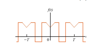
When t= -x we observe that f(-x) =f(x) since it is even function.
 =
=  =
= 
Which does show that integrating from -T/2 to 0 is the same as integrating from 0 to T/2
Therefore
Ak = 2/T  + 2/T
+ 2/T 
 =
=  =-
=- 
Similarly
 =
=  =
= 
To find the Fourier coefficients the integration lies between 0 and T/2.
Odd function symmetry
A periodic function is defined to be odd if f( t) = -f(t) due to the fact that polynomial functions with only odd exponents behave this way.
The expression is
Av= 0 ; ak = 0 for all k;
Bk = 4/T 
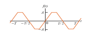
The evenness (oddness) of a function can be dismantled by shifting the periodic function along the time axis.
Example:
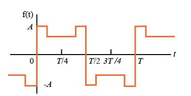
For the following diagram explain whether it is even or odd.
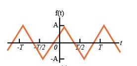
Solution:
The signal is neither even nor odd.
To make the signal even there is a slight shift to be applied as shown in the figure.
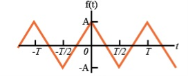
To make the signal odd

Half-wave symmetry:
A periodic signal satisfying the condition
x(t) = -x(t ± T/2)
Is said to half symmetry . The Fourier series expansions of such type of periodic signals contains odd harmonics only.
Example:
Show that the signal x(t) that satisfies half wave symmetry contains Fourier coefficients with odd harmonics only.
A signal with half-wave symmetry that satisfies the condition x(t+T/2) = - x(t)
The Fourier coefficients of the signal are
Cn = 1/T  Ω0 dt
Ω0 dt
= 1/T [ Ω0 dt +
  Ω0 dt
Ω0 dt
= 1/T  Ω0 dt +
  Ω0 dt
Ω0 dt
=  Ω0 dt -
 Ω0 dt
Ω0 dt
Here e-jnπ = 1 for n Even.
Hence Cn=0
Ω0 = 2π/T
Quarter-wave symmetry
If a function has half-wave symmetry and symmetry about the midpoint of the positive and negative half-cycles, the periodic function is said to have quarter--wave symmetry.
Problems:
Find the trigonometric Fourier series for the periodic signal x(t) as shown in the figure.
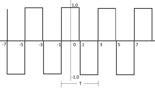
For the given signal the period T =4.
For our convenience let us choose one period signal from t= -1 to t=3
That is t0=-1 and t0+ T =3.
The fundamental frequency
 = 2 π/T =2 π/4= π/2.
x(t) = { 1 for -1 ≤t ≤1
-1 for 1≤t≤3}
a0= 1/T 
= ¼  = ¼[
= ¼[  +
+  ]
]
= ¼ [ t |-1 1 + (-t)| 1 3 ]
= ¼ [ 1 – (-1) – (3-1)] = 0
a0 = 0.
An = 2/T 
½ 
= ½  +
+ 
= ½ [ 2/ nπ sin(nπ/2t) | -1 1 - 2/nπ sin(nπ/2t)|1 3
= ½ [ 8/nπ sin(nπ/2)] = 4/nπ sin(nπ/2)
An=4/nπ sin(nπ/2)
Bn = 1/2 
= ½  +
+ 
= ½ [ -2 /nπ cos(nπ/2t) | -1 1 + 2/nπ cos(nπ/2t) | 1 3
= -2/nπ(cosnπ/2 – cos nπ/2) + 2/nπ (cos 3nπ/2 – cosnπ/2)
= 0
Therefore 4/nπ sinnπ/2 = { 0 n even
4/nπ = 1,,9,13…..
- 4/nπ 3,7,11,15…….
x(t) = 
= 4/π cos (π/2 t) – 4/3π cos (3π/2 t)+ 4/5π cos(5π/2 t) - …………..
= 4/π [ cos(π/2 t) -1/ 3 cos( 3π/2 t ) + 1/5 cos (5 π/2 t) – 1/7 cos(7π/2 t) + ………..
Exponential Fourier Series
The exponential Fourier series is another form of Fourier series. Using Euler’s identity we cam write
An cos(Ω0nt +  n ) = An [ ej(Ω0nt +
  n) –e -j(Ω0nt +
  n)
n)
x(t) = A0 +  ej(Ω0nt +
  n) –e- j(Ω0nt +
  n)]
n)]
= A0 +  ej(Ω0nt ) ej
  n) –e- j(Ω0nt ) . ej
  n)
n)
= A0 +  ej
ej n ) ej(Ω0nt ) + (An/2 e-j
  n ) e- j(Ω0t ) ] -------- (1)
Let n=-k
x(t) = A0 +  ej
ej n ) ej(Ω0nt ] +
  ej
ej  k ) e j(Ω0kt ) ------- (2)
Comparing (1) and (2) we get
An = Ak (- n ) =
n ) =  k n>0 k<0-------------------(3)
Let us define c0 = A0; cn =An/2 ej n for n>0
By changing the index from k to n and combining into one equation we get
x(t) = A0 +  ej
ej n ) ej(Ω0nt) +
  ej
ej n) ej(Ω0nt)]
x(t) =  n ej(Ω0nt) ]
The above series is known as Exponential Fourier Series.
To develop the coefficients of the the exponential Fourier series
We know that
x(t) =  n ej(Ω0nt) ] where Ω0 = 2π/T
Multiply e-jk Ω0 t and integrate over one period. Then
 e-jk Ω0 t dt =
  cn ej(Ω0nt) ] e-jk Ω0 t dt
=  cn
cn  ej(Ω0nt) e-jk Ω0 t dt
Substituting the relation  e-jk Ω0 t dt = 0 for k ≠n and T when k=n
 e-jk Ω0 t dt = T ck
Therefore
Ck = 1/T  e-jk Ω0 t dt
Or
Cn = 1/T  e-jk Ω0 t dt
Where cn are the Fourier series coefficients of exponential Fourier series.
Problems:
- Compute the Exponential series of the following series.

The time period of the signal x(t) isT=4.
Ω0 = 2π/T = 2 π/4= π/2
C0 = 1/T  = ¼ [
= ¼ [ +
+ 
C0 = ¼ [ 2+1 ] = ¾
Cn = 1/T [  e-jnΩot dt = ¼[
 e-jnπ/2t dt +
  e-jn π/2t dt
= ½. 1/ -jn π/2 [e-jn π/2t ] 0 1 + ¼ 1/-jn π/2[ e-jn π/2t ] 1 2
= - 1/jn π[e-jn π/2 – 1] – 1/ 2jn π (e-jn π – e-jn π/2 )
= 1/jn π[ 1 - e-jn π/2 ] – 1/ 2 e-jn π + ½ e-jn π/2 )
= 1/jn π [ 1- ½ (-1) n -1/2 e-j n π/2 ]
Key takeaway
In Fourier series
a0 = 1/T 
An = 2/T 
Similarly
Bn=2/T 
For exponential Fourier Series
Cn = 1/T  e-jk Ω0 t dt
Average Value:
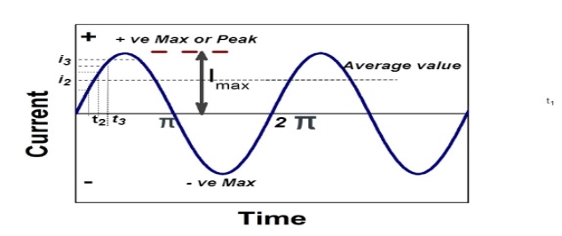
Fig 1 Sinusoidal waveform
The arithmetic mean of all the value over complete one cycle is called as average value

 =
= 
For the derivation we are considering only hall cycle.
Thus  varies from 0 to ᴫ
i = Im Sin


Solving
We get


Similarly, Vavg=
The average value of sinusoid ally varying alternating current is 0.636 times maximum value of alternating current.
RMS value: Root mean square value
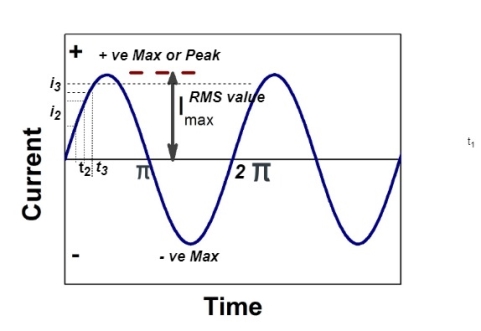
Fig 2 Sinusoidal waveform
The RMS value of AC current is equal to the steady state DC current that required to produce the same amount of heat produced by ac current provided that resistance and time for which these currents flows are identical.

I rms = 
Direction for RMS value:
Instantaneous current equation is given by
i = Im Sin 
But 
I rms = 
= 
=
=
Solving
=
=
Similar we can derive
V rms=  or 0.707 Vm
 the RMS value of sinusoidally alternating current is 0.707 times the maximum value of alternating current.
Reactance
- Inductive Reactance (XL)
It is opposition to the flow of an AC current offered by inductor.
XL = ω L But ω = 2 ᴫ F
 XL = 2 ᴫ F L
It is measured in ohm
 XL∝FInductor blocks AC supply and passes dc supply zero
2. Capacitive Reactance (Xc)
It is opposition to the flow of ac current offered by capacitor
Xc = 
Measured in ohm
 Capacitor offers infinite opposition to dc supply
Impedance (Z)
The ac circuit is to always pure R pure L and pure C it well attains the combination of these elements. “The combination of R1 XL and XC is defined and called as impedance represented as
Z = R +i X
Ø = 0
 only magnitude
R = Resistance, i = denoted complex variable, X =Reactance XL or Xc
Polar Form
Z =  L I
L I
Where  =
=
 Measured in ohm
Power factor (P.F.)
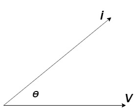
It is the cosine of angle between voltage and current

If Ɵis –ve or lagging (I lags V) then lagging P.F.
If Ɵ is +ve or leading (I leads V) then leading P.F.
If Ɵ is 0 or in phase (I and V in phase) then unity P.F.
Steady state behavior of RLC circuit with excitation
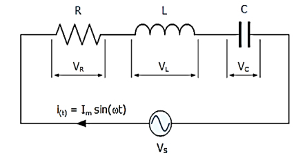
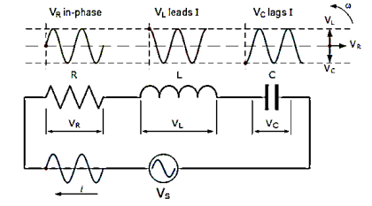
The series RLC circuit is shown below. Let current i(t) be sinusoidal. The value of instantaneous voltage across R is in phase with current. The instantaneous voltage across L leads current by 900. The instantaneous voltage across C lags current by 90o.
Writing the loop equations, we get
Vs-VR-VL-VC=0
VS-IR-L -
- = 0
= 0
VS= IR + L +
+ 
The voltage triangle will be
Vs=
VR = iRsin t
t
VL= iXLsin t+90)
t+90)
VC= iXcsin t-90)
t-90)
Z = =
Impedance Z= 
Key takeaway
V rms=  or 0.707 Vm
 the RMS value of sinusoidally alternating current is 0.707 times the maximum value of alternating current.
Examples
Q) For a series RLC circuit having R=10ohms, L= 0.15H, C=100 F. They are connected across 100v 50Hz supply. Calculate total impedance?
Sol: Impedance Z= 
Z=  = 18.27ohm
Q) For a series RLC circuit having R=12ohms, L= 0.2H, C=60 F. They are connected across 100v 50Hz supply. Calculate circuit current?
Sol: I= 
Z= 
Z=  = 13.89ohm
I = 100/13.89 =7.2A
Q) For a series RLC circuit having R=10ohms, L= 0.15H, C=100 F. They are connected across 100v 50Hz supply. Calculate power factor?
Sol: cosφ = 
Impedance Z= 
Z=  = 18.27ohm
Cosφ =  =
= 
φ = 56.81o lagging
Sinusoidal Steady State Analysis:
1) The method used is phasor method.
2) Take Laplace transform of R, L and C in the circuit.
3) Make all initial conditions zero.
4) Derive the expression for desired voltage and current.
5) Replace S by jω where ω is the frequency at which the circuit is operating.
Que) If V1=6cos2t, find i2 at steady state.
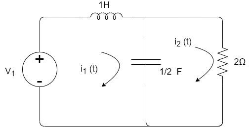
Sol: Apply KVL
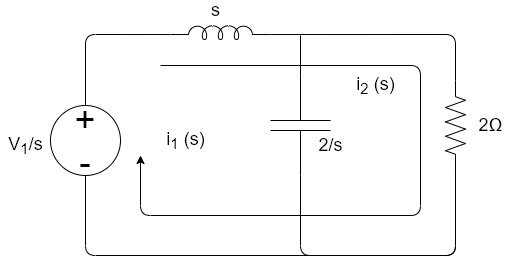
6 -sI1(s)-2I2(s)=0
-2I2(s)- I2(s)+
 I1(s)=0
I2(s) =
= I1(s)
I1(s)
I1(s)= [
[ I2(s)
I2(s)
Substituting I1(s) in first equation
6 -s
-s [
[ }I2(s)- 2I2(s)=0
Solving above equation we get
I2(s)=
Replace s=jω, s=2j
I2(jω)= =
= =
=
=
Que) If V1=2sin2t, Va at steady state will be?
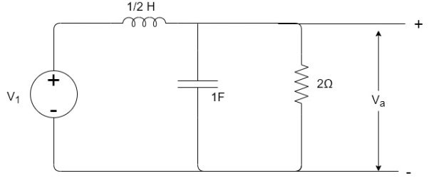
Sol: Zeq=
After Laplace Transform the above circuit will be
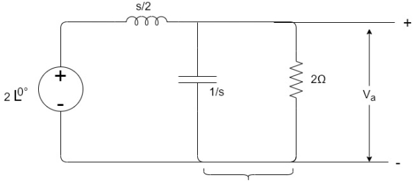
By voltage divider rule Va=
Replace s by jω , s=2j
Va= =
=
Va= =
=
Va=
Fourier Integral
The formula for the decomposition of a non periodic function into harmonic components whose frequencies range over a continuous set of values.
If a function f(x) satisfies the Dirichlet condition on every finite interval and if the integral
 converges then
F(x) = 1/π 
 --------- (1)
The formula was first introduced by J. Fourier in connection with the solution of certain heat conduction problems but was proved later by other mathematicians.
Formula(1) can also be given in the form
f(x) =  ------- (2)
Where
a(u) = 1/π 
b(u) = 1/π 
In particular for even functions
f(x) =  where
where
a(u) = 2/π 
By taking the limits of Fourier series for functions with period 2T as T -> ∞
Then a(u) and b(u) are analogues of the Fourier coefficients of f(x)
Using complex numbers we can replace formula (1) with
f(x) = 1/2π 
 e ju(x-t) f(t)
f(x)= lim 1/π  sin
sin  dt x-t
This is called Fourier Integral.
Problem:
1.Find the Fourier integral of
f(x) = |sin x| |x| ≤ π
= 0 |x| ≥ π
Deduce that  π +1/ 1 - 2 cos (π/2) d = π/2
Solution:
f(x) = 2/π 

= t
t =
= 
=
= - cost(1-) ]0 π - cost(1+) ]0 π
2(1-) 2(1+)
= 1/ 1- 2 [cos π+ 1]
= π +1/ 1 - 2 cos (π/2) d = π/2
Find the Fourier Integral of
f(x) = 1 |x| ≤ 1
0 |x| ≥ 1
f(x) = 1/π  (t-x) dt d
= 1/π  dt d
dt d
= 1/π / ] -1 1 d
= 1/π  -
-  / d
/ d
= 1/π  – sin
– sin  ]/ d
]/ d
= 2/π  / d = π/2 when |x| < 1 and 0 when |x| >1
By setting x=0
=  / d = π/2.
Fourier Transform
Consider a periodic signal f(t) with period T. The complex Fourier series representation of f(t) is given as
f(t) =  k ejkw0t
=  k ej2π/T0kt -------- (1)
Let 1/T0 =  f then equation (1) becomes
f(t) =  k ej2π
 kft --------------- (2)
But you know that
Ak = 1/ T0  e-jkw0t dt
Substitute in eq(2)
f(t) = 
 e-jkw0t dt ej2πk
  ft
ft
Let to = T/2 then

 e-j2πkt
  dt ej2πkt
  ft
ft  f
f
As lim T-> ∞  f approaches differential df, k
  f becomes continuous variable hence summation becomes integration
f(t) = lim T-> ∞ { 
 e-j2πk
  ft dt] ej2πk
  ft
ft  f
f
= 
 e-j2π ft dt] ej2π ft df
f(t)= 
 ejwt dw
Where F(w) =  e-j2π ft dt
Fourier transform of a signal is given by
f(t) = F(w) =  e-jwt dt
And Inverse Fourier transform is given by
f(t) =  ejwt dw
Fourier transform are classified into
- Continuous Fourier transform and
- Discrete Fourier transform.
Continuous Fourier Transform
Fourier series was defined for periodic signals. A periodic signals can be considered as a periodic signal with fundamental period
Consider a periodic square wave:
x(t) = 1 for |t| < T1
= 0 T1< |t| < T0/2
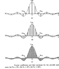
The fourier series co-efficient is
Ak = 2 sin(kwoT1)
k wo T0
To.ak = 2 sin(wT1) | w=kw0
W
Key takeaway
Operation |  |  |
Scalar multiplication Addition Conjugation Duality Scaling (a real) Time shifting Frequency shifting (  Time convolution Frequency convolution Time differentiation
Time integration
|           
|            |
Three Phase
In three phase the windings are separated by 1200 each. The voltage produced in those windings are 1200 apart from each other. Below shown is one coil RR’ and two more coils YY’ and BB’ each having phase shift of 1200.
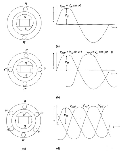
The instantaneous value of voltages is given as
VRR’ = Vmsinωt
VYY’ = Vmsin(ωt-120)
VBB’ = Vmsin(ωt-240)
The three phase voltages are of same magnitude and frequency.
Phase sequence
The change in voltage is in order VRR’- VYY’- VBB’. So, the three-phase are changed in that order and are called as phase change.
VRR’ = Vmsinωt
VYY’ = Vmsin(ωt-120)
VBB’ = Vmsin(ωt-240)
Phasor Diagram
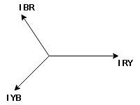
We are getting resultant line current IR by subtracting 2 phase currents IRY and IBR  take phase currents at reference as shown
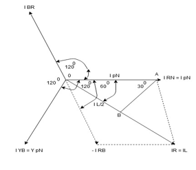
Cos 300 = 
 =
= 
IL = Iph
Iph
- Complete phases diagram for delta connected balanced Inductive load.
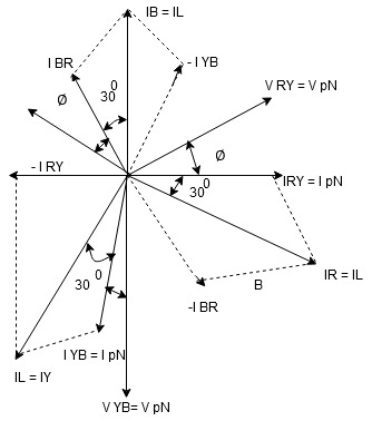
Phase current IYB lags behind VYB which is phase voltage as the load is inductive
Star Connection:
In this type similar ends are connected to common point called as neutral and having a star shape. These connections are used in case of unbalanced current flowing in the three-phase. To avoid any kind of damage we use this connection.
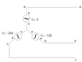
Line voltage VL =  Vphase
Line current IL = Iphase
Delta Connection:
There are three wires with no neutral. They are used for short distance due to unbalanced current in circuit.
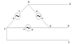
Line voltage VL = Vphase
Line current IL =  Iphase
Power relation for delta load star power consumed per phase
PPh = VPh IPh Cos Ø
For 3 Ø total power is
PT= 3 VPh IPh Cos Ø …….①
For star
VL and IL = IPh (replace in ①)
 PT = 3
  IL Cos Ø
 PT = 3
  VL IL Cos Ø – watts
For delta
VL = VPh and IL =  (replace in ①)
PT = 3VL
= 3VL  Cos Ø
Cos Ø
 PT
PT VL IL Cos Ø – watts
Total average power
P =  VL IL Cos Ø – for ʎ and
  load
load
K (watts)
Total reactive power
Q =  VL IL Sin Ø – for star
  delta load
K (VAR)
Total Apparent power
S =  VL IL – for star
  delta load
K (VA)
Three Phase Unbalanced Circuits
If the load connected across the three phases are not identical to each other, which means they have different magnitudes and power factors. These kinds of loads are known as unbalanced loads. The phase currents in delta and phase or line current in star connections differ in unbalanced loading, giving rise to flow of current in neutral wire.
IN = IR+IY+IB
Unbalanced Delta-connected loads
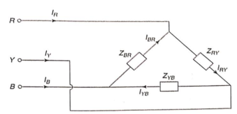
Fig 3 Unbalance Delta connected load
For delta load
VL = Vph


Phase currents are given by


Unbalanced three wire star connected load
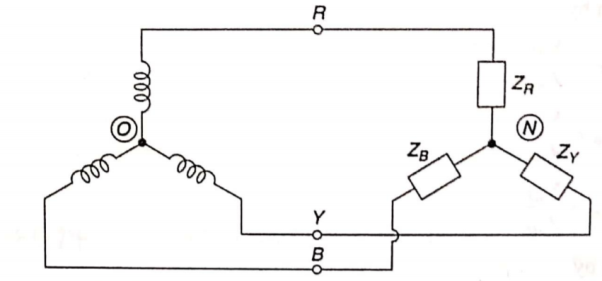
Fig 4 Unbalanced three wire star connected load
If neutral N of the load is not connected to the neutral point O of the supply, there exists a voltage between the supply neutral point and the load neutral point. The load phase voltage is not the same as the supply phase voltage. There are many methods to solve such networks. Most commonly used are
- Star Delta Transformation
In star transformation, the star connected loads are replaced by equivalent delta connected loads.


The problem is then solved as an unbalanced delta connected load. The line current so calculated are equal to the line currents of the original star connected load.
- Millman’s Theorem
An unbalanced three wire star connected load can also be solved by Millman’s Theorem. Let VRO, VYO and VBO be the phase voltages of supply, which are equal in magnitude but differ in phase from each other by 120o. Let VRN, VYN and VBN be the load phase voltages, which are unequal in magnitude as well as differ in phase by unequal angles. The voltages between the neutral points, N and O, VNO is calculated using Millman’s theorem.

Where YR, YB and YY are the admittances of the branches of the unbalanced star connected load. The voltage across phase impedance or load phase voltage can be calculated as


The phase currents in the load are given as


For star load line current is equal to phase current.
Solved Examples
Q1) Three similar resistors are connected in star across 400V 3-phase lines. Line current is 4A. Calculate the value of each resistor.
Sol: For star connection:
IL=Iph=4A
Vph=VL/ = 400/
 = 231V
Rph= 231/4= 57.75ohm
For Delta Connection:
IL=4A
Iph= IL/
=4/ ==2.30A
Zph=400/2.30=173.9ohm
Rph= 173.9/3 = 57.97ohm
Q2) Three identical impedances are connected in delta 3-phase supply of 400V. The line current is 30A and total power taken from the supply is 10kW. Calculate the resistance and reactance value of each impedance?
Sol: VL=Vph=400V
IL=30A
Iph=IL/ = 30/
= 30/ =17.32A
Zph=Vph/Iph= 400/17.32=23.09ohm
P= VLIL Cos Ø
Cos Ø = 10000/ 400x30 = 0.48
Sin Ø =0.88
Rph=Zph Cos Ø= 23.09x0.48=11.08ohm
Xph=Zph Sin Ø = 23.09x0.88=20.32ohm
Q3) A star connected alternator supplies a delta connected load. The impedance of the load branch is 6+j5 ohm/phase. The line voltage is 230V. Determine the current in the load branch and power consumed by the load.
Sol: Zph= = 7.8ohm
VL=Vph=230V
Iph=Vph/Zph=230/7.8=29.49A
Iph=IL/
IL=  Iph=
Iph= x29.49=51.07A
P= VLIL Cos Ø =
  x 230x51.07x0.768=15.62kW
Q4) The load connected to a 3-phase supply comprise three similar coils connected in star. The line currents are 25A and the kVA and kW inputs are 18 and 10 respectively. Find the line and phase voltage, the kVAR input resistance and reactance of each coil?
Sol: IL= 25A
P= 10000W
Cos Ø = 10/18 = 0.56
P= VLIL Cos Ø
10000= x VLx25x0.56
VL =412.39V
Vph= VL/ = 412.39/
 =238.09V
KVAR= = 14.96
Zph=238.09/25=9.52ohm
Rph=Zph Cos Ø= 9.52x0.56=5.33ohm
Xph=Zph Sin Ø = 9.52x0.83=7.88ohm
Q5) A balanced delta connected load consisting of three coils draws 8 A at 0.5 p.f from 100V 3-phase ac supply. If the coils are reconnected in star across the same supply. Find the line current and total power consumed?
Sol: For Delta connection:
IL=8 A
A
Iph= IL/ = 8A
= 8A
Vph=100V
Zph=100/8=12.5ohm
Rph=Zph Cos Ø=12.5x0.5 = 6.25ohm
Xph=Zph Sin Ø = 12.5x0.866=10.825ohm
P= VLIL Cos Ø
=  x 100x 8
 x0.5=1200W
For Star Connection:
Vph= VL/ = 100/
 V=57.73V
Zph=100/8=12.5ohm
Iph=57.73/12.5=4.62A
P= VLIL Cos Ø
= x 100x 4.62x0.5
P= 400W
Q6) A 3-phase supply with a line voltage of 250V has an unbalanced delta connected load as shown in figure
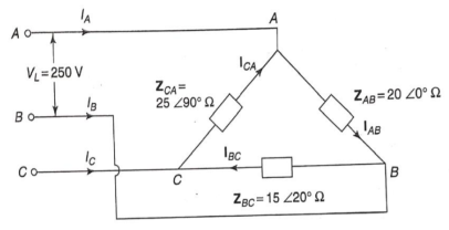
Find (a) Phase current (b) line current?
Sol: From above figure we can write


The phase currents are


The Line currents are


Q7) Find vc(t) for circuit shown in the figure?
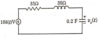
Sol: Let the current in circuit be i(t). From KVL we have

Taking F.T we get

As i(0+) =0 hence I(0)=0


Takin IFT we get

Q8) Find Fourier transform of the waveform given below?
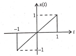
Sol:


Q9) Find the Fourier series coefficients for the given saw tooth wave(in exponential form) as shown in figure

Sol:


Q10) A continues time periodic signal x(t) has a fundamental period T=8. The nonzero Fourier series coefficients for x(t) are: 𝑎1 = 𝑎−1 = 2. 𝑎3 = 𝑎∗−3 = j4
Express x(t) in the form of-

Sol:


Here, 
Therefore,

Q11) For the circuit shown in figure, Determine the voltage response 𝑣𝑜 𝑡 to a current source excitation i(t)=2𝑒−𝑡𝑢(𝑡), using Fourier transform?
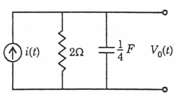
Sol: We apply KCL

Taking FT of both sides we have

Therefore,

By partial fraction of above equation, we get

Taking IFT of above equation we get

Q12) In the Circuit of fig., A 400 V, 50 Hz, three phase supply of phase sequence ABC is supplied to a delta connected load consisting of a 100 Ohm resistor between lines A and B, a 378 mH inductor between lines B and C, and a 37.8 micro farad capacitor between lines C and A. Determine Phase and line currents.
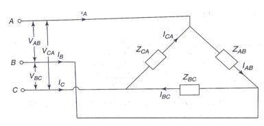
Sol: VL = 400V, f=50Hz, R= 100 Ohm, L= 318mH, C=31.8 micro farad


Phase Current


Line Currents


References:
1. Franklin F. Kuo, “Network Analysis and Synthesis,” Wiley India Education, 2nd Ed., 2006.
2. Van, Valkenburg, “Network analysis,” Pearson, 2019.
3. Sudhakar, A., Shyammohan, S. P., “Circuits and Network,” Tata McGraw-Hill New
Delhi, 1994.
4. A William Hayt, “Engineering Circuit Analysis,” 8th Edition, McGraw-Hill Education.
5. A. Anand Kumar, “Network Analysis and Synthesis,” PHI publication, 2019.