UNIT 1
Review of signals and systems
Signal:
A signal is a description of how one parameter varies with another parameter.

Fig.1: Signal
For example: voltage changing over time in an electronic circuit.
System
A system is a process that produces an output signal in response to an input signal.

Fig.2: Communication System
As illustrated in the figure system produces output signal in response to an input signal.
Classification of Systems
Continuous –time System and Discrete Systems
A continuous time system is one which operates on the continuous time input signal and produces a continuous-time output signal.


 x(t) y(t)
Fig.3: CT system
If the input is x(t) and output is y(t) then
y(t) = T{x(t)}
That is x(t) is transformed to y(t).
Example: Amplifiers, filters, motors etc
Discrete time system is one which operates on discrete time input signal and produces a discrete-time output signal.


 x(n) y(n)
Fig.3: DT system
If the input is x(n) and output y(n) then
y(n) = T[x(n)]
Static and Dynamic Systems
A system is said to be static or memoryless if its output at any instant depends on the input at that instant but not on the past or future values of input.
Otherwise the system is dynamic or with memory.
Example for static:
y(t) = x2(t)
y(n) = nx(n)
Example for dynamic
y(t) = dx(t)/dt
y(n) = x(n-1)
Find whether the following systems are dynamic or not:
a) y(t) = x(t-2)
Here, the output depends on the past value of input therefore the system is dynamic
b) y(n) = x(n+2)
The output depends on the future value of input. Therefore, system is dynamic.
c) y(t) = x2(t)
The output depends on the present input .Therefore system is static.
Linear and Non-linear Systems.
Superposition principle states that the response to a weighted sum of input signals be equal to the weighted sum of the outputs corresponding to each of the individual input signals. A system that satisfies the superposition principle is said to be linear system.
T [a1 x1(t) + a2 x2(t)] = a1 T[x1(t)] + a2 T[x2(t)]
∴, T [a1 x1(t) + a2 x2(t)] = a1 y1(t) + a2 y2(t)
Similarly, for discrete –time linear system
T [ax1(n) + bx2(n)] = a T[x1(n) + bTx2(n)]
Example:
Check whether the systems are linear or not.
a) dy/dt + 3t y(t) = t2 x(t)
b) y(t) = 
c) y(n) = Ax(n) + B
Solution:
a) dy/dt + 3t y(t) = t2 x(t)
For input x1(t) the output is y1(t)
Dy1(t)/dt + 3t y1(t) = t2 x1(t) --------- (1)
Similarly, for x2(t) output is y2(t)
Dy2(t)/dt + 3t y2(t) = t2 x2(t) ---------- (2)
Multiply (1) with a and (2) with b
a dy1(t) /dt + 3at y1(t) + b dy2(t)/dt + 3by2(t) = at2 x1(t) + bt2 x2(t)
d/dt[ay1(t) +by2(t)] + 3t[ay1(t) + by2(t)] = t2[ax1(t) + bx2(t)]
The system is linear because weighted sum of inputs produces the corresponding weighted sum of outputs.
b) y(t) = 
For x1 input output is y1(t)
y1(t) =
y2((t) 
Linear combination of both yields
 ay1(t) + by2(t) = a
  + b
+ b 
 =
= 
Linear combination of inputs
Linear combination of outputs
Therefore, system is linear.
c) y(n) = Ax(n) + B
For input x1(n) the corresponding output is y1(n)
y1(n) = T[x1(n)] = Ax1(n) + B ; y2(n) = Tx2(n)] = A x2(n) + B
Ay1(n) + by2(n) = a[Ax1(n) + B] + b[Ax2(n) +B]
The output will be y3(n) = A[x1(n) + x2(n) ] +B
y3(n) ≠ ay1(n) + by2(n)
Therefore, system is non-linear.
d) y(t) = e x(t)
y1(t) = e x1(t)
y2(t) = e x2(t)
y3(t) = T[ax1(t) + b x2(t) ] = e[ax1(t)+bx2(t)]
Ay1(t) + by2(t) = a ex1(t) + b ex2(t)
y3(t) ≠ ay1(t) + b y2(t)
Hence, system is not linear.
Time Variant and Time Invariant Systems
A system is said to be time-variant if its input-output characteristics does not change with time.
Suppose we apply a signal(t) to a system to a system and obtain an output y(t) as shown in the figure.
If we delay by T seconds then for a time-invariant system the output will be delayed by T seconds.
Example
Determine whether the following systems are time variant or time invariant.
a) y(t) = x(t) cos 50πt
b) y(t) = e x(t)
c) y(t) = x(t2)
d) y(n) = x2(n-1)
a) y(t) = x(t) cos 50πt
If the input is delayed by T sec then output
y(t,T) = T[x(t-T)] = x(t-T) cos (50πt)
If the output is delayed by T sec then
y(t-T) = x(t-T) cos 50 π(t –T)
y(t,T) ≠ y(t – T)
Hence the system is time-variant.
b) y(t) = ex(t)
The output for delayed input is
y(t,T) = e x(t-T)
The delayed output is
y(t-T) = ex(t-T)
y(t,T) = y(t-T)
Hence, system is time-invariant.
c)y(t) = x(t2)
The output for delayed input is
y(t,T) = x(t2 –T)
The delayed output is
y(t-T) = x(t-T)2
y(t,T) ≠ y(t – T)
Hence the system is time variant
d) y(n) = x2 (n-1)
The output for delayed input is
y(n-k) = x2(n-1-k)
The delayed output is
y(n-k) = x2 (n-1-k)
y(n,k) = y(n-k)
System is time invariant.
Causal and Non-casual systems.
System is said to be casual if its output depends on the present and past inputs and not on the future input.
If the output depends on the future inputs then it is non- casual system.
For example
y(t) = 2 x(t) + 3 x(t-3)
Let t=1 therefore y(1) = 2 x(1) + 3 x(-2)
The system output only depends upon present and past inputs. Hence, the system is causal.
y(t) = 2 x(t) + 3 x(t – 3) + 6 x( t+3)
Let t=1 the system output is
y(1) = 2x(1) + 3 x(-2) + 6 x( 4)
Here the output depends future input. Hence non –casual.
Invertible and Non-Invertible systems
A system is said to invertible if the input of the system appears at the output.

Fig.4: Invertible system
Y(S) = X(S) H1(S) H2(S)
= X(S) H1(S) · 1(H1(S))/ (H1( S)) Since H2(S) = 1/( H1(S) )
∴, Y(S) = X(S)
→ y(t) = x(t)
Hence, the system is invertible.
If y(t) ≠ x(t), then the system is said to be non-invertible.
To test whether the system is invertible or not:
- If the system produces zero output for any input the system is non-invertible.
- If the system gives same output for different inputs the system is non-invertible.
Stable and Unstable Systems
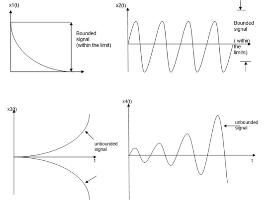
Fig.5: Stable and unstable system
An input signal x(t) is said to be bounded if it satisfies the condition |x(t) |≤Mx < ∞ for all t.
Similarly, the output signal is bounded if it satisfies the condition |y(t)| ≤My < ∞
The example for bounded and unbounded signals is as shown in the figure.
Note: For a bounded signal, amplitude is finite.
Example 1: y (t) = x2(t)
Let the input is u(t) that is unit step then output y(t) = u2(t) = u(t) = bounded output.
Hence, the system is stable.
Example 2: y (t) = ∫x(t)dt
Let the input be u (t) then
Output y(t) = ∫u(t)dt but ∫ u(t)dt = ramp signal
It is unbounded because the amplitude of ramp is not finite and tends to become infinite when t →infinite
Hence, the system is unstable.
Problems:
Check whether the following systems are
Static or dynamic
Linear or Non-linear
Causal or non-casual
Time Invariant or time variant
a) y(t) d2y(t) /dt2 + 3t dy(t)/dt + y(t) = x(t)
- Since it is a differential equation the system is dynamic.
- The input x1(t) and output y1(t) can be described by
y1(t) d2 y1(t)/dt2 + 3t dy1(t)/dt + y1(t) = x1(t)
Similarly, y2(t) d2y2(t)/dt2 + 3t dy2(t)/dt + y2(t) =x2(t)
a y1(t) d2y1(t)/dt2 + 3at dy1(t)/dt + a y1(t) + b y2(t) d2y1(t)/dt2 + 3bt dy1(t)/dt +by2(t) = ax1(t) + b x2(t)
Ay1 d2 y1(t)/dt2 + by2(t) d2 y(t)/dt2 + 3t d/dt[ay1(t) + b2 y2(t)] + ay1(t) + b y2(t) = ax1(t) + bx2(t)
Since the differentiation ay1(t) d2 y1(t)/dt2 + by2(t) d2 y2(t)/dt2 is not a function of the weighted sum of outputs, superposition principle is not satisfied hence the system is non-linear.
- The output depends on the present input only hence the system is causal.
- The co-efficient of the differential equations are function of time. Hence the system is time-variant.
b) y(n) = x(n) x(n-1)
The output depends the past values of input. Hence it requires memory therefore the system is dynamic.
The output y1(n) for input x1(n) is
y1(n) = x1(n) x1(n-1)
y2(n) = x2(n) x2(n-1)
y3(n) = ax1(n) + b x2(n) [ax1(n-1)+ b x2(n-1)]
a y1(n) + by2(n) = a x1(n) x1(n-1) + bx2(n) x2(n-1)
Since y3(n) ≠ ay1(n) + b y2(n)
Hence the system is non-linear.
The output depends on the present and past values of input. Hence, the system is casual.
y(n) = x(n) x(n-1)
y(n,k) = x(n-k) x(n-1-k)
y(n-k) = x(n-k) x(n-1-k)
Since y(n,k) = y(n-k) the system is time-invariant.
c) y (n) = cos[x(n)]
The output depends on the input at that instant. Therefore, system is static.
For input x1(n)
y1(n) = cos[x1(n)]
For input x2(n)
y2(n) = cos[x2(n)]
y3(n) = cos[ax1(n) + b x2(n)]
a y1(n) + b y2(n) = a cos [x1(n)] + b cos[x2(n)]
Hence the system is non-linear.
The output depends on the present input hence the system is casual.
y(n) = cos[x(n)]
y(n,k) = cos[x(n-k)]
y(n-k) = cos[x(n-k)]
y(n,k) = y(n-k)
Hence system is time –invariant.
For the given system check whether the system is linear, time-invariant, casual memoryless or stable.
Y(t) = x(t-2)+ x(2-t)
- System is not memoryless since the output depends on the past and future values of input.
- The system is non-casual since output depends on the future values of input.
y(t, = x1(t-2-
 )+x1(2-t-
 )
)
y(t- ) = x(t-2-
 ) + x2(2-t+
 )
)
y(t, ≠ y(t-
System is time variant.
y1(t) = x1(t-2) + x1(2-t)
y2(t) = x2(t-2) + x2(2-t)
a1y1(t) + a2 y2(t) = a1 x1(t-2)+ a1x1(2-t) + a2x2(t-2)+a2x2(2-t)
= a1x1(t-2) + ax2(t-2) +a1x1(2-t)+a2 x2(2-t)
= System is linear.
For bounded input, the output is also bounded. Hence the system is stable.
- Standard Test Signal
We need to obtain the response of the signal for a specific input. But the question is, the input can be varying signal or sometimes random signal. Therefore, some standard test signals are required to know the performance of the system. Thus, the standard input signals include:
- An impulse
- Step
- Ramp
- Parabolic input.
Impulse Signal 
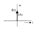
Fig.6: Impulse signal
The impulse response is as shown in the figure.
- The impulse response is zero for t ≠ 0.
- It rises to infinity at t = 0– and comes back to zero at t = 0+ enclosing a finite area.
- If this area is A it is called as an impulse function of strength A.
- If A = 1 it is called a unit impulse function.
Thus an impulse signal is denoted by f(t) = A (t).
Properties on Impulse function:
 = x(0)
 =x(t0)
 = x(t0)
 1/|a|
1/|a| 
 =x(t)
=x(t)
Evaluate the following integrals:

 (t-3) 2 dt
Solution:
1) 
 = 1 for t=0. For t≠ 0 =0.
=  |t=0 = 0
2)  (t-3) 2 dt for t=3
  = 1
= 1
(t-3) 2 |t=3 =0
Step Signal
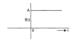
Fig.7: Step signal
The step signal is as shown in the figure.
- For t<0 it is zero.
- For t=0 it rises to A
- For t>0 it remains the same.
Thus, the step signal is denoted by f(t) = A u(t). If A=1 it is called unit step function.
Ramp Signal
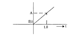
Fig.8: Ramp signal
The ramp signal is as shown in the figure.
- For t<0 it is zero.
- Uniformly increases with slope = A.
It is denoted by f(t) = At. If the slope is unity then it is called a ramp signal.
Unit Parabolic Signal
A unit parabolic signal, p(t) is defined as,
p(t) = t2/2; t≥0
=0; t<0 and t=0
We can write unit parabolic signal p(t) in terms of unit step signal u(t) as
P(t) = t2/2 u(t).
The following figure shows the unit parabolic signal.
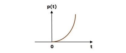
Fig.9: Unit Parabola signal
Key Takeaways:
- A signal is a description of how one parameter varies with another parameter.
- A system is a process that produces an output signal in response to an input signal
A signal is said to be periodic if it satisfies the condition x (t) = x (t + T) or x (n) = x (n + N).
Where T = fundamental time period,
ω0= fundamental frequency = 2π/T
There are two basic periodic signals:
x(t) = cos wot (sinusoidal)
x(t) = e jwot (complex exponential)
These two signals are periodic with period T=2π/ω0
A set of harmonically related complex exponentials can be represented as ɸk(t)
ɸk(t) = {e jkwot} = {e jk(2π/T)t} where k=0,±1,±2,±3,………………(1)
All these signals are periodic with period T.
According to orthogonal signal space approximation of a function f(x) with n mutually orthogonal functions is given by
x(t) =  e jkwot ……………………………………………….(2)
= k ejkwot
Where ak= Fourier coefficient = coefficient of approximation.
This signal x(t) is also periodic with period T.
Equation 2 represents Fourier series representation of periodic signal x(t).
The term k = 0 is constant.
The term k=±1 having fundamental frequency ω0, is called as 1st harmonics.
The term k=±2 having fundamental frequency 2ω0, is called as 2nd harmonics, and so on...
The term k=±n having fundamental frequency nω0, is called as nth harmonics.
Deriving Fourier Coefficient
We know that x(t) =  e jkwot ------------------------(1)
Multiply e-jnwot on both sides we get
x(t) e -jnwot =  e jkwot . e- jnwot
Consider integral on both sides we get
 e jkwot dt =
  e jkwot . e- jnwot
=  e j(k-n)wot dt
=  e jkwot dt =
 j(k-n)wot dt --------------------------(2)
By Eulers formula
 j(k-n)wot dt =
  wo dt + j
  wo dt
wo dt
 j(k-n)wot dt = { T k=n
0 k  n
n
Hence in equation (2) the integral is zero for all values of k except at k=n. Put k=n is equation 2
=  j(k-n)wot dt = anT
=an = 1/T  -jnwot
Replace n by k we get
= ak = 1/T  -jkwot dt
x(t) = e j(k-n) wot
Where ak = 1/T  -jkwot dt
DSB – FC: Double side band full corner Modulated signal can be represented as,
Xc( t ) = [ Ac + Am Cos ( 2 ∏ fm t ) ]cos ( 2 ∏ fc t )
M = Am / Ac - - - - - called modulation depth
Xc( t ) = Ac [ 1 + Am / Ac cos ( 2 ∏ fm t ) ] cos (wct )
Xc( t ) = Ac [ 1 + m Cos 2 ∏ fm t ] cos wct
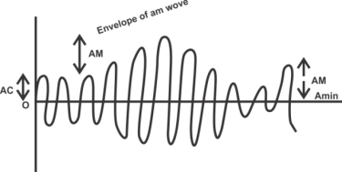
Fig.10: DSB-FC
The value of modulation index depends on Am and Ac. But it has to lie between ‘0’ to ‘1’ i.e 0 \< m \< 1
When m > 1 it is called over modulation. It leads to distortion after demodulation. Hence over modulation should be avoided.
The modulating signal x (t) can be signal sinusoidal. This is called tone modulation.
Frequency domain description of AM [spectrum of AM]:
Fourier transform of x (t) be X (f).
 X (t) X (f)
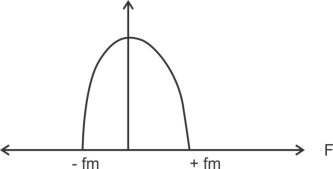
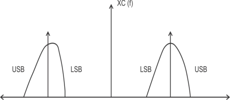
Fig.11: Frequency in AM
The frequency spectrum of AM signal consists of corner frequency and the upper and lower side band. Hence the AM is also called double side band full corner or DSB FC.
Total bandwidth of the AM signal is 2fm where fm is highest frequency component present in the modulating signal x (t).
Bandwidth of AM = fc + fm – (fc – fm)
= fc + fm – fc + fm
BW = 2fm
Power Relation in AM wave:
Pc = Ac2 / 2 or Pc = Ac2 / 2R - - - where this R is antenna resistance
PUSB = m2 Ac2 / 8
PLSB = m2 Ac2 / 8
Total power of AM signal for single tone modulation is,
Pt = Pc + PLSB + PUSB
Pt = Ac2 / 2 + m2 Ac2/ 8 + m2 Ac2/8
Pt = Ac2 / 2 [ 1 + m2 / 2 ]
Pc = Ac2 / 2R
The modulation index can be expressed as
M = √ 2(Pt / Pc – 1)
The carrier does not carry any information. The information is contained in the side hand. Hence high carrier power should be avoided.
Transmission efficiency of AM wave
x = Total sideband power / Total transmitted power
x = PLSB + PUSB / Pt
For single modulation tone
x = m2 Ac2 / 8 + m2 Ac2 / 8 / Pc [ 1 + m2 / 2 ]
= m2 / 4 Pc + m2 / 4 Pc / Pc [ 1 + m2 / 2 ] - - - - - - > as, Pc = Ac2 / 2
= m2 / 2 / 1 + m2 / 2
X = m2 / 2 + m2
PLSB = PUSB = m2 Ac2 / 2R
Modulation index in terms of vtg:
M = √ 2 ( Vt / Vc ) 2 – 1
Prob :- Ac = 5V, Am = 2V. Find m, Pt
M = Am / Ac = 2 / 5 = 0.4
Pc = Ac2 / 2 = 25 / 2 = 12.5 watt
PLSB = PUSB = m2 Ac2 / 8 = (0.4)2 25 / 8
= 0.5 watt
Pt = Pc + PLSB + PUSB
= 12.5 + 0.5 + 0.5
= 35.5 watt
P= m2 / 2 + m2 = (0.4)2 / 2 + ( 0.4 )2
= 0.16 / 2 + 0.16
= 0.074 = 7.4 %
Measurement of Modulation index by using Envelope:

Fig.12: Envelop for modulation
M = Am / Ac
Am = Amax – Amin / 2
Ac = Amax + Amin / 2
M = Amax – Amin / Amax + Amin
Trapezoid method can also be used to measure modulation index
The modulating signal is applied to vertical deflection circuit & modulating signal to horizontal circuit [XY mode]. The resultant shape displayed on screen.


Fig.13: Resultant shape displayed on screen
Generation of AM signal:
The AM signal can be generated using two methods
1>. Using Analog Multiplier
2>. Using Nonlinear Resistance Device
Practical AM generation Technique:
Circuit wise we can divide the amplitude modulator circuit in two types
1>. Discrete component ‘s amplitude modulators
2>. Integrated circuits ( IC ) amplitude modulators
Transmission method wise categorization can be given as
1>. High level modulation [ Broadcasting purpose] - - > (class ‘ c’ amplifier used to give high efficiency )
2>. Low level modulation [ Laboratory purpose] :-
Generated AM wave is then amplified using a chain of linear amplifiers like Class A, Class B, Class AB, etc.
Collector Amplitude Modulator:
To reduce eddy current & hysteresis losses at high frequency air core transformer is used for o/p stage of collector amplitude modulator.
RF choke (Rfc) is used to block high frequency AM< wave with carrier interfering to Af modulating transformer.
Neutralization is mostly used in the amplifiers which are either RF tune damper or working at frequency above 25 MHz.
There are four methods of neutralization to avoid the parasitic oscillations. These are
1>. Hazeltine neutralization method
2>. Rice neutralization method
3>. Cross neutralization method
4>. Direct neutralization method
Low level Amplitude Modulators:
1>. Emitter injection transistorized AM modulator
2>. Base injection transistorized AM modulator
3>. FET AM modulator
Double Sideband Suppressed Carrier:
In AM signal DSB –FC contains carrier which is filtered at the receiver and has no information. Thus, AM signal has a bandwidth of 2fm Hz where fm is bandwidth of message signal. Thus, AM occupies double the bandwidth of message signal.
A modulation technique in which the modulated signal contains no carrier and has only sidebands been called Double sideband suppressed carrier modulation.
The bandwidth of DSB – SC is 2fm where fm is highest frequency component or bandwidth of modulating signal.
It is used in forming chrominance signal in NTSC & PAL colour T.V. Systems.
DSB – SC is first step in generation of DSB – SC signal.
The total power of DSB – SC modulated signal for a sinusoidal modulating signal is equal to sum of powers of upper & lower side band signals.
PUSB – SC = PUSB + PLSB
PLBS = PUSB = m2 Ac2 / 8R
PDSB – SC = m2 Ac2 / 8R + m2 Ac2 / 8R
= m2 Ac2 / 4R
= m2 2PC R / 4R
PDSB – SC = m2 / 2 x PC
PDSB – SC = (1 + m2 / 2) PC
Total power of the PDSB – SC signal will be
Pt = PLSB + PUSB
Generation of DSBSC:
DSBSC modulated signal can be generated using
1> Multiplier Modulator
2> Balanced Modulator
3> Ring Modulator used in telephone circuits Balance modulator It consists of four diodes which forms a ring.
A square wave carrier fc is used for switching these diodes.
Thus DSB – SC with carrier frequencies of fc, 3fc, 7fc, etc are produced in the o/p because the sequence carrier signal has only the fundamental and odd harmonics.
Key Takeaways:
- The frequency spectrum of AM signal consists of corner frequency and the upper and lower side band. Hence the AM is also called double side band full corner or DSB FC.
- The AM signal can be generated using two methods
1>. Using Analog Multiplier
2>. Using Nonlinear Resistance Device
SSB – SC has only one sideband to be transmitted hence there is significant reduction of power and bandwidth.
SSBSC technique has following disadvantages.
1>. The receiver for SSB – SC is more complex because of the absence of carrier and another sideband.
2>. Practically it is not easy to suppress the other sideband as it is very close to the sideband which has to be retained.
Methods of Generation of SSB – SC signal:
There are mainly two methods of generation of SSB – SC modulated signals.
1>. Filter method or Balance modulator filter method
In this method we first generate a DSB – SC signal and then filter out the unwanted sideband.
2>. Phasing method
3>. Variant of phasing method named weaver’s method
4>. Third method having advantages of filter and phase shift method.
In television we need to transmit both video & audio signals.
Amplitude modulation is used for video & frequency modulation is used for audio transmission in T.V.
The video signal has a bandwidth of 5 MHz. If AM is used the bandwidth of modulated signal will be 10 MHz hence not suitable.
SSB – SC cannot be used for following reasons,
1>. The receiver for SSB – SC is complex and expensive.
2>. Commercial T.V. Broad casting requires high level. Suppression of sidebands which is difficult to achieve at transmitter using phasing method.
3>. The video signals have considerable d.c & low frequency component present in it. This prevents use of filtering method which require hole in low frequency part of spectra.
4>. Phase response of band pass filter used in filter method is non-linear near passband edge. Hence the received video signal is distorted.
Vestigial sideband (VSB) modulation is used in T.V. Signal since AM & SSB – SC is not suitable.
In VSB carrier one sideband and part of another sideband (vestige) is also transmitted.
VSB Application in T.V. Broadcasting: -
Modulation Method | Power Requirement | Bandwidth Requirement | Demodulation or receiver requirement |
AM | Highest | 2fm | Simple diode detector is required |
DSB | Less than AM | 2fm | Complex circuit containing balanced modulators are required. |
SSB | Lowest | Fm | Complex circuit containing balanced modulators are required. |
VSB | Less than AM (moderate) | Less than AM (BW < 2 fm ) | Simple diode detector is required in T.V. Receiver. |
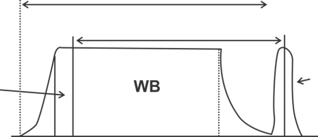
Fig.14: Vestigial Band
The VSB modulation is used for modulating video (picture) signal only. Thus, above figure clearly indicate that if AM is used for video signal the bandwidth will become 11.25 MHz using VSB modulation technique a part of LSB is taken & hence the bandwidth of one channel becomes 7 MHz.
Key Takeaways:
- Vestigial sideband (VSB) modulation is used in T.V. Signal since AM & SSB – SC is not suitable.
- In VSB carrier one sideband and part of another sideband (vestige) is also transmitted.
References:
1. Haykin S., "Communications Systems," John Wiley and Sons, 2001.
2. Proakis J. G. And Salehi M., "Communication Systems Engineering," Pearson Education,
2002.
3. Taub H. And Schilling D.L., "Principles of Communication Systems,” Tata McGraw Hill,
2001.
4. Wozencraft J. M. And Jacobs I. M., “Principles of Communication Engineering,” John
Wiley, 1965.
5. Barry J. R., Lee E. A. And Messerschmitt D. G., “Digital Communication,” Kluwer
Academic Publishers, 2004.
6. Proakis J.G., “Digital Communications',' 4th Edition, McGraw Hill, 2000.
7. Abhay Gandhi, “Analog and Digital Communication,” Cengage publication, 2015.