UNIT-III
Probability and Random Process
Probability is the measure of the likelihood that an event will occur in a Random Experiment. Probability is quantified as a number between 0 and 1, where, loosely speaking, 0 indicates impossibility and 1 indicates certainty. The higher the probability of an event, the more likely it is that the event will occur.
Example
A simple example is the tossing of a fair (unbiased) coin. Since the coin is fair, the two outcomes (“heads” and “tails”) are both equally probable; the probability of “heads” equals the probability of “tails”; and since no other outcomes are possible, the probability of either “heads” or “tails” is 1/2 which could also be written as 0.5 or 50%.
Conditional probabilities arise naturally in the investigation of experiments where an outcome of a trial affects the outcomes of the subsequent trials.
We try to calculate the probability of the second event (event B) given that the first event (event A) has already happened. If the probability of the event changes when we take the first event into consideration, we can safely say that the probability of event B is dependent of the occurrence of event A.
For example
- Drawing a second ace from a deck given we got the first ace
- Finding the probability of having a disease given you were tested positive
- Finding the probability of liking Harry Potter given we know the person likes fiction
Here there are 2 events:
- Event A is the probability of the event we are trying to calculate.
- Event B is the condition that we know or the event that has happened.
Hence we write the conditional probability as P ( A/B), the probability of the occurrence of event A given that B has already happened.
P(A/B) = P( A and B) / P(B) = Probability of occurrence of both A and B / Probability of B
Suppose you draw two cards from a deck and you win if you get a jack followed by an ace (without replacement). What is the probability of winning, given we know that you got a jack in the first turn?
Let event A be getting a jack in the first turn
Let event B be getting an ace in the second turn.
We need to find P(B/A)
P(A) = 4/52
P(B) = 4/51 {no replacement}
P(A and B) = 4/52*4/51= 0.006
P(B/A) = P(A and B)/ P(A) = 0.006/0.077 = 0.078
Here we are determining the probabilities when we know some conditions instead of calculating random probabilities
Statistical Independence
Statistical independence is a concept in probability theory. Two events A and B are statistically independent if and only if their joint probability can be factorized into their marginal probabilities, i.e.,
P(A ∩ B) = P(A)P(B).
If two events A and B are statistically independent, then the conditional probability equals the marginal probability:
P(A|B) = P(A) and P(B|A) = P(B).
The concept can be generalized to more than two events. The events A1, …, An are independent if and only if
P(⋂i=1n Ai)=∏i=1 nP(Ai)
Key Take-Aways:
- Probability is the measure of the likelihood that an event will occur in a Random Experiment.
- Statistical independence is a concept in probability theory.
It is a stochastic process (a collection of random variables indexed by time or space), such that every finite collection of those random variables has a multivariate normal distribution, i.e. every finite linear combination of them is normally distributed. The distribution of a Gaussian process is the joint distribution of all those (infinitely many) random variables, and as such, it is a distribution over functions with a continuous domain, e.g. Time or space.
White noise is often used to model the thermal noise in electronic systems. By definition, the random process X(t) is called white noise if SX(f) is constant for all frequencies. By convention, the constant is usually denoted by N0/2
The random process X(t) is called a white noise process if
SX(f)=N0/2, for all f.
Before going any further, let's calculate the expected power in X(t). We have
E[X(t)2]=∫SX(f)df=∫ N0/2df=∞
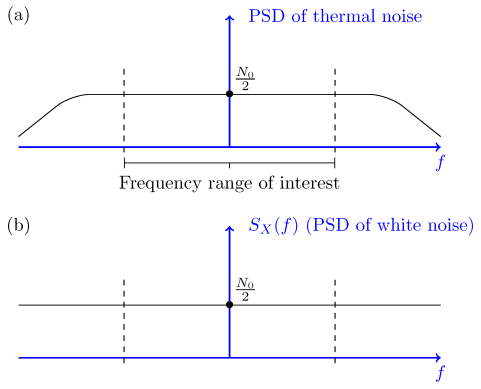
Thus, white noise, as defined above, has infinite power! In reality, white noise is in fact an approximation to the noise that is observed in real systems. To better understand the idea, consider the PSDs shown in Figure

Figure 1- Part (a): PSD of thermal noise; Part (b) PSD of white noise.
Part (a) in the figure shows what the real PSD of a thermal noise and the PSD of the white noise is shown in Part (b) are approximately the same.
The thermal noise in electronic systems is usually modeled as a white Gaussian noise process. It is usually assumed that it has zero mean μX=0 and is Gaussian.
The random process X(t) is called a white Gaussian noise process if X(t) is a stationary Gaussian random process with zero mean, μX=0, and flat power spectral density,
SX(f)=N0/2, for all f
Since the PSD of a white noise process is given by SX(f)=N0/2, its autocorrelation function is
RX(τ)=F−1{N0/2}=N0/2δ(τ),
Where δ(τ) is the dirac delta function
δ(x)= 0, x=0 otherwise 1 for x=1
Example
Let X(t) be a white Gaussian noise process that is input to an LTI system with transfer function
|H(f)|={21<|f|<20 otherwise
If Y(t) is the output, find P (Y (1) <N0).
Solution
Since X(t)X(t) is a zero-mean Gaussian process, Y(t) is also a zero-mean Gaussian process. SY(f) is given by

Therefore,

= 4 .
.
Thus,
Y
To find P(Y(1)<

= Φ 
Key Take-Aways:
- White noise is often used to model the thermal noise in electronic systems. By definition, the random process X(t) is called white noise if SX(f) is constant for all frequencies.
- The PSD of a white noise process is given by SX(f)=N0/2, its autocorrelation function is
RX(τ)=F−1{N0/2} = N0/2δ(τ)
Thermal Noise
Thermal noise is the electronic noise generated by thermal agitation of charge carriers inside an electrical conductor in equilibrium, which happens regardless of any applied voltage.
Movement of electrons will form kinetic energy in the conductor related to temperature in the conductor.
When the temperature increases the movement of electrons increases and current flows through the conductor.
Current flows due to free electrons which create noise voltage n(t).
Noise voltage is influenced by temperature hence it is called thermal noise.
Q. Calculate the thermal noise power available from any resistor at room temperature (290K) for a bandwidth of 1Mhz. Calculate also the corresponding noise voltage given that R = 50 Ω.
Pn = 1.38 x 10 -23 x 290 x 10 6
= 4 x 10 -15.
En2 = 4 x 50 x 1.38 x 10 -23 x 290
= 0.895 µ V
Shot Noise
Shot noise arises because the current consists of a vast number of discrete charges.
The continuous flow of these discrete pulses gives rise to almost white noise. There is a cut-off frequency by the time it takes for the electron or other charge carrier to travel through the conductor.
Unlike thermal noise, this noise is dependent upon the current flowing and has no relationship to the temperature at which the system is operating.
Shot noise is more apparent in devices such as PN junctions. The electrons are transmitted randomly and independently of each other.
Partition Noise
When the circuit is to divide in between two or more paths then the noise generated is known as Partition noise. The reason for this generation is random fluctuation in the division.
Flicker Noise
Flicker noise or modulation noise is the one appearing in transistors operating at low audio frequencies. Flicker noise is proportional to the emitter current and junction temperature. However, this noise is inversely proportional to the frequency.
Burst Noise
Burst noise consists of step-like transitions suddenly between two or more discrete voltages or current levels.
Each shift in offset voltage or current lasts for millisecond to seconds. It is also known as popcorn noise because of the popping or crackling sound it produces in audio circuits.
Avalanche Noise
Avalanche noise is the noise produced when a junction diode is operated at the onset of avalanche break down, a semiconductor junction phenomenon in which the carriers having high voltage gradient develop sufficient energy to dislodge additional carriers through physical impact creating ragged current flow.
NOISE IN DSB-SC SYSTEM:
Let the transmitted signal be
u(t) = Ac m(t) cos(2πfct) -----------------------(1)
The received signal at the output of the receiver noise- limiting filter: sum of this signal and filtered noise. A filtered noise process can be expressed as in-phase and quadrature component as
n(t) = A(t) cos[ 2πfct +  ] --------------------------(2)
= A(t) cos([ 2πfct) cos  - sin(2πfct) sin
  ----------------------(3)
Where nc(t) is in phase component and ns(t) in quadrature component.
Received signal (Adding the filtered noise to the modulated signal)
r(t) = u(t) + n(t) ----------------------------(4)
Ac m(t) cos (2πfct) + nc(t) cos(2πfct) – ns(t) sin(2πfct)------------------------(5)
Demodulate the received signal by first multiplying r(t) by a locally generated sinusoid cos(2πfct + ) where is the phase of the sinusoid.. Passing the product signal through the ideal low pass filter having bandwidth W
The multiplication of r(t) with cos(2πfct + ) yields
= r(t) cos(2πfct + )-----------------------------(6)
= u(t) cos(2πfct + ) + n(t) cos(2πfct + )-----------------------------(7)
= Ac m(t) cos(2πfct + ) cos(2πfct + )----------------------------------(8)
= ½ Ac m(t) cos( ) + ½ Ac m(t) cos(4πfct + ) + ½ [nc(t) cos( ) + ns(t) sin()] + ½ [nc(t) cos(4πfct + ) – ns(t) sin(4πfct + )]------------------------------------(9)
NOISE in SSB-SC SYSTEM
Let SSB modulated signal is
u(t) = Ac m(t) cos(2πfct ) ± Ac m^(t) sin(2πfct) -------------------------(1)
Input to the demodulator be
r(t) = Ac m(t) cos(2πfct) + Ac m^(t) sin(2πfct) + n(t) -----------------------(2)
= Ac m(t) cos(2πfct) + Ac m^(t) sin(2πfct) + nc(t) cos(2πfct) - ns(t) sin(2πfct)]-------(3)
= [Ac m(t) + nc(t)] cos(2πfct) + [Ac m^(t) –ns(t)] sin(2πfct) ------------------------(4)
Assumption: Demodulation with an ideal phase reference
Hence the output of the low pass filter is the in-phase component (with a co-efficient of ½) with the preceding signal.
Po =P2/4 PM
Pno = ¼ Pnc = ¼ Pn --------------------------------------- (5)
(S/N)0 = Po/Pno = (Ac2 /PM) / WNo
Pn =  = No/2 x 2W = WNo
PR = PU = Ac2 PM
(S/N)0 SSB = PR / N0 W = (S/N)b
The signal-to-noise ratio in an SSB system is equivalent to that of a DSB system.
Key Take-Aways:
- When the temperature increases the movement of electrons increases and current flows through the conductor.
- Current flows due to free electrons which create noise voltage n(t).
- Noise voltage is influenced by temperature hence it is called thermal noise.
- The signal-to-noise ratio in an SSB system is equivalent to that of a DSB system.
Noise generally is spread uniformly across the spectrum (the so-called white noise, meaning wide spectrum). The amplitude of the noise varies randomly at these frequencies.
FM systems are inherently immune to random noise. In order for the noise to interfere, it would have to modulate the frequency somehow.
But the noise is distributed uniformly in frequency and varies mostly in amplitude. As a result, there is virtually no interference picked up in the FM receiver.
FM is sometimes called "static free, " referring to its superior immunity to random noise.
White Noise
White noise plays an important role in modelling of WSS signals. A white noise process W(t) is a random process that has constant power spectral density at all frequencies.
Thus
S w(w) = N0/2 ----------------(1) - ∞<w<∞
Where No is real constant and called the intensity of the white noise. The corresponding autocorrelation is given by
Rw( = N/2
= N/2  (
( where
where  (
( is the Dirac delta.
The average power of white noise
P wg = E W 2 = 1/2π dw -> ∞
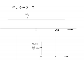
The autocorrelation function and the PSD of white noise process is shown in Figure.

Fig.2 : White noise
Key Take-Aways:
The average power of white noise
P wg = E W 2 = 1/2π dw -> ∞
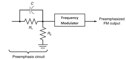
- Pre-emphasis: The noise suppression ability of FM decreases with the increase in the frequencies. Thus, increasing the relative strength or amplitude of the high frequency components of the message signal before modulation is termed as Pre-emphasis. The Fig3 below shows the circuit of pre-emphasis.

Fig3. Pre-emphasis circuit
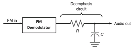
- De-emphasis: In the de-emphasis circuit, by reducing the amplitude level of the received high frequency signal by the same amount as the increase in pre-emphasis is termed as De-emphasis. The Fig4. Below shows the circuit of de-emphasis.

Fig4. De-emphasis circuit
- The pre-emphasis process is done at the transmitter side, while the de-emphasis process is done at the receiver side.
- Thus, a high frequency modulating signal is emphasized or boosted in amplitude in transmitter before modulation. To compensate for this boost, the high frequencies are attenuated or de-emphasized in the receiver after the demodulation has been performed. Due to pre-emphasis and de-emphasis, the S/N ratio at the output of receiver is maintained constant.
- The de-emphasis process ensures that the high frequencies are returned to their original relative level before amplification.
- Pre-emphasis circuit is a high pass filter or differentiator which allows high frequencies to pass, whereas de-emphasis circuit is a low pass filter or integrator which allows only low frequencies to pass.
Key Take-Aways:
- By increasing the relative strength or amplitude of the high frequency components of the message signal before modulation is termed as Pre-emphasis.
- In the de-emphasis circuit, by reducing the amplitude level of the received high frequency signal by the same amount as the increase in pre-emphasis is termed as De-emphasis.
- At low SNRs, the signal is not distinguishable from the noise and a mutilation or threshold effect is present. –There exists a specific SNR at the input of the demodulator known as the threshold SNR, beyond which signal mutilation occurs.
- The existence of the threshold effect places an upper limit on the trade-off between bandwidth and power in an FM system. –This limit is a practical limit in the value of the modulation index βf

Key Take-Aways:
Threshold Effect. The signal will be lost in the noise if the input SNR is small.
References:
1. Haykin S., "Communications Systems," John Wiley and Sons, 2001.
2. Proakis J. G. And Salehi M., "Communication Systems Engineering," Pearson Education,
2002.
3. Taub H. And Schilling D.L., "Principles of Communication Systems,” Tata McGraw Hill,
2001.
4. Wozencraft J. M. And Jacobs I. M., “Principles of Communication Engineering,” John
Wiley, 1965.
5. Barry J. R., Lee E. A. And Messerschmitt D. G., “Digital Communication,” Kluwer
Academic Publishers, 2004.
6. Proakis J.G., “Digital Communications',' 4th Edition, McGraw Hill, 2000.
7. Abhay Gandhi, “Analog and Digital Communication,” Cengage publication, 2015.