UNIT-5
Digital Modulation
In this, the phase of the carrier signal is modulated to represent the signal levels, while amplitude and frequency remains constant.
Binary Phase Shift Keying (BPSK) is the simplest form of PSK where there are two signal elements represented by two different phases.
In Quadrature PSK (QPSK), two bits of information are transmitted per symbol by using four different phases.
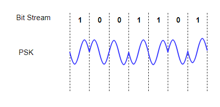
Fig.1: PSK
PSK is of two types, depending upon the phases the signal gets shifted. They are −
Binary Phase Shift Keying BPSK
This is also called as 2-phase PSK or Phase Reversal Keying. In this technique, the sine wave carrier takes two phase reversals such as 0° and 180°.
BPSK is basically a Double Side Band Suppressed Carrier DSBSC modulation scheme, for message being the digital information.
Quadrature Phase Shift Keying QPSK
This is the phase shift keying technique, in which the sine wave carrier takes four phase reversals such as 0°, 90°, 180°, and 270°.
If this kind of techniques are further extended, PSK can be done by eight or sixteen values also, depending upon the requirement.
The block diagram of Binary Phase Shift Keying consists of the balance modulator which has the carrier sine wave as one input and the binary sequence as the other input. Following is the diagrammatic representation.
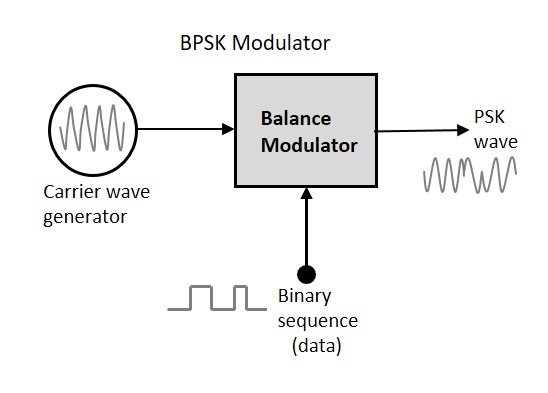
Fig. 2 : BPSK modulator
The modulation of BPSK is done using a balance modulator, which multiplies the two signals applied at the input. For a zero-binary input, the phase will be 0° and for a high input, the phase reversal is of 180°.
Following is the diagrammatic representation of BPSK Modulated output wave along with its given input.
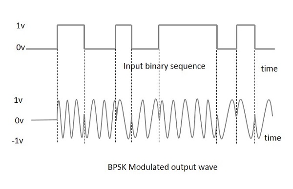
Fig.3 : BPSK modulated output
The output sine wave of the modulator will be the direct input carrier or the inverted 180°phaseshifted180°phaseshifted input carrier, which is a function of the data signal.
Key Takeaways:
- In this, the phase of the carrier signal is modulated to represent the signal levels, while amplitude and frequency remains constant.
- Binary Phase Shift Keying (BPSK) is the simplest form of PSK where there are two signal elements represented by two different phases.
- In Quadrature PSK (QPSK), two bits of information are transmitted per symbol by using four different phases.
In FSK, the frequency of the signal is modulated to represent the signal levels, while amplitude and phase remains constant.
To represent the signal levels 0 and 1, two different frequencies are used.
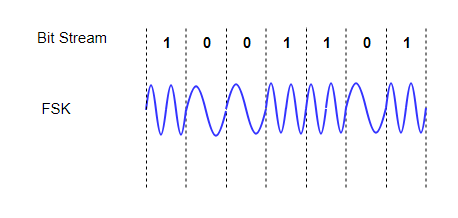
Fig.4: FSK
FSK Modulator
The FSK modulator block diagram comprises of two oscillators with a clock and the input binary sequence. Following is its block diagram.
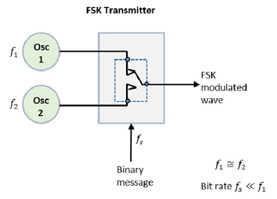
Fig.5: FSK modulator
The two oscillators, producing a higher and a lower frequency signals, are connected to a switch along with an internal clock. To avoid the abrupt phase discontinuities of the output waveform during the transmission of the message, a clock is applied to both the oscillators, internally. The binary input sequence is applied to the transmitter so as to choose the frequencies according to the binary input.
FSK Demodulator
There are different methods for demodulating a FSK wave. The main methods of FSK detection are asynchronous detector and synchronous detector. The synchronous detector is a coherent one, while asynchronous detector is a non-coherent one.
Asynchronous FSK Detector
The block diagram of Asynchronous FSK detector consists of two band pass filters, two envelope detectors, and a decision circuit. Following is the diagrammatic representation.
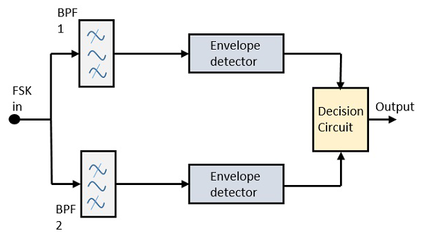
Fig.5: FSK demodulator
The FSK signal is passed through the two Band Pass Filters BPFs, tuned to Space and Mark frequencies. The output from these two BPFs look like ASK signal, which is given to the envelope detector. The signal in each envelope detector is modulated asynchronously.
The decision circuit chooses which output is more likely and selects it from any one of the envelope detectors. It also re-shapes the waveform to a rectangular one.
Key Takeaways:
- In FSK, the frequency of the signal is modulated to represent the signal levels, while amplitude and phase remains constant.
- To represent the signal levels 0 and 1, two different frequencies are used.
QAM is a combination of ASK and PSK. Here, both the amplitude and the phase are varied to transmit more bits per symbol.
QAM utilises both amplitude and phase components to provide a form of modulation that is able to provide high levels of spectrum usage efficiency.
It is a signal in which two carriers shifted in phase by 90 degrees (i.e. sine and cosine) are modulated and combined. Because of their 90° phase difference, they are in quadrature. Here, one signal is called the In-phase or “I” signal, and the other is the quadrature or “Q” signal.
The resultant overall signal consists of both I and Q carriers which has both amplitude and phase variations. Therefore, it may also be considered as a mixture of amplitude and phase modulation.
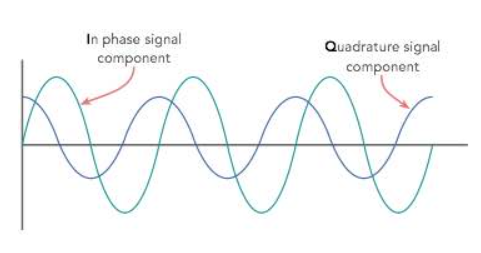
Fig3: QAM
Continuous phase modulation (CPM) is a constant-amplitude modulation scheme that is a generalization of continuous phase frequency shift-keying (CPFSK) or minimum shift-keying (MSK). The lack of phase discontinuities reduces high-frequency spectral content, making CPM a highly spectrally efficient scheme.
One form of CPM that can result in significant coding gains is multi-h phase coding, where h stands for the modulation index. This scheme is a generalization of CPFSK schemes because different phase changes result from the transmission of the same symbol in two contiguous symbol intervals. A mathematical representation of the signal during the ith interval, iT ≤ t (i + 1)T, is expressed by the following formula:

Where Es is the symbol energy
T is the symbol duration
ωc is the carrier frequency in radians/second
d and ω are the sequences that represent the M-ary information sequence
The data phase terms diωi(t - iT) and φ correspond to the phase associated with the current data symbol and the phase accumulation due to the previous data symbol such that
And

where  is the angular frequency corresponding to the modulation index used during the ith baud. The different values of h can be used between symbol intervals in a round robin fashion.
Key Takeaways:
- Continuous phase modulation (CPM) is a constant-amplitude modulation scheme that is a generalization of continuous phase frequency shift-keying (CPFSK) or minimum shift-keying (MSK).
References:
1. Haykin S., "Communications Systems," John Wiley and Sons, 2001.
2. Proakis J. G. And Salehi M., "Communication Systems Engineering," Pearson Education,
2002.
3. Taub H. And Schilling D.L., "Principles of Communication Systems,” Tata McGraw Hill,
2001.
4. Wozencraft J. M. And Jacobs I. M., “Principles of Communication Engineering,” John
Wiley, 1965.
5. Barry J. R., Lee E. A. And Messerschmitt D. G., “Digital Communication,” Kluwer
Academic Publishers, 2004.
6. Proakis J.G., “Digital Communications',' 4th Edition, McGraw Hill, 2000.
7. Abhay Gandhi, “Analog and Digital Communication,” Cengage publication, 2015.