Unit 3
Fourier Series
A signal is said to be periodic if it satisfies the condition x (t) = x (t + T) or x (n) = x (n + N).
Where T = fundamental time period,
ω0= fundamental frequency = 2π/T
There are two basic periodic signals:
x(t) = cos wot (sinusoidal)
x(t) = e jwot (complex exponential)
These two signals are periodic with period T=2π/ω0
A set of harmonically related complex exponentials can be represented as ɸk(t)
ɸk(t) = { ejkwot} = { e jk(2π/T)t} where k=0,±1,±2,±3,………………(1)
All these signals are periodic with period T.
According to orthogonal signal space approximation of a function f(x) with n mutually orthogonal functions is given by
x(t) =  e jkwot ……………………………………………….(2)
= k ejkwot
Where ak= Fourier coefficient = coefficient of approximation.
This signal x(t) is also periodic with period T.
Equation 2 represents Fourier series representation of periodic signal x(t).
The term k = 0 is constant.
The term k=±1 having fundamental frequency ω0, is called as 1st harmonics.
The term k=±2 having fundamental frequency 2ω0, is called as 2nd harmonics, and so on...
The term k=±n having fundamental frequency nω0, is called as nth harmonics.
Deriving Fourier Coefficient
We know that x(t) =  e jkwot ------------------------(1)
Multiply e-jnwot on both sides we get
x(t) e -jnwot =  e jkwot . e-jnwot
Consider integral on both sides we get
 e jkwot dt =
  e jkwot. e-jnwot
=  e j(k-n)wotdt
=  e jkwot dt =
  j(k-n)wot dt --------------------------(2)
By Eulers formula
 j(k-n)wot dt =
  wo dt + j
  wo dt
wo dt
 j(k-n)wot dt = { T k=n
0 k  n
n
Hence in equation (2) the integral is zero for all values of k except at k=n. Put k=n is equation 2
=  j(k-n)wot dt = anT
=an = 1/T  -jnwot
Replace n by k we get
= ak = 1/T  -jkwot dt
x(t) = e j(k-n) wot
Where ak = 1/T  -jkwot dt
Key Takeaways:
- Fourier series definition
- Derivation and Representation
Aperiodic signals in continuous time are represented by the Fourier transform
An aperiodic signal can be viewed as a periodic signal with an infinite period
As the period becomes infinite, the frequency components form a continuum and the Fourier series becomes an integral
The (CT) Fourier transform (or spectrum) of x(t) is
X(jw) =  e -jwt dt ---------------------------------------(1)
x(t) can be reconstructed from its spectrum using the inverse Fourier transform
x(t) = 1/ 2 π e jwtdw ------------------------------------------(2)
The above two equations are referred as Fourier transform pair with the first one being the analysis equation and the second being the synthesis equation.
Notation
X(jw) = F{x(t)}
x(t) = F -1 {X(jw)}
x(t) and X(jw) form a Fourier transform pair denoted by
 x(t) F X(jw)
Example :
Rect(t) or π(t) = 1 |t|  ½
½
0 |t| > ½
½ |t| =1/2
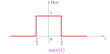
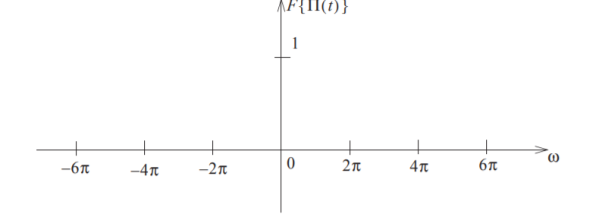
Figure1.Fourier transform of rect of rect(t)
Key Takeaways:
- What is fourier transform.
- Derivation and Representation
If x1(t) and x2(t) are both periodic with period T and the Fourier series co-efficient of x1(t) and x2(t) are cn and dn respectively then
FS[x1(t) x2(t) ] =  dn-l
dn-l
Proof:
FS[x1(t) x2(t) ] = 1/T  x2(t) e – jnΩot dt ------------------------(1)
Using synthesis equation, we write
x 1 (t) =  l e jlΩot --------------------------------------(2)
x 2(t) =  k e jkΩot ---------------------------------------(3)
Substituting (2) and (3) in (1) we get
FS[x1(t) x2(t) ] = 1/T  l e jlΩot
  k e jkΩot e – jnΩot dt-----------------(4)
= 1/T = 1/T  l e jlΩot d k e jkΩot e – jnΩot dt --------------------(5)
= l d k ∂ (n –(k+l)) -------------------------------(6)
=  l d n-l ------------------------------------------(7)
Key Takeaways:
- Convolution its definition
- Derivation and representation
H(e jw) = H R ( e jw) + j H I ( e jw) = | H ( e jw) | e j  1 (w)
1 (w)
 1 (w) = angle H(e jw)
Example:
h[n] = - δ[n]
| H (ejw)| = 1 angle H(e jw) = π
In the magnitude or phase representation a real valued frequency response does not mean that the system is zero-phase.
Using this representation,
|Y (ejw) | = | H ( ejw)| | X (ejw)|

Thus, |H(ejω)| and angle H(ejω) are commonly referred to as the gain and the phase shift of the system, respectively.
In magnitude and phase plots, as ω goes through a zero on the unit circle, the magnitude will go to zero and the phase will flip by π, as shown in the figure below.
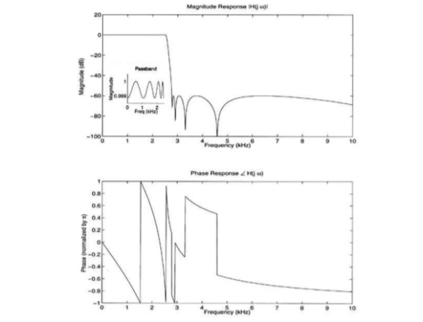
Figure2. Fourier transform magnitude and frequency response
Representation of Fourier transform
- Magnitude Response
- Frequency Response
The Duality property is very useful because it can enable to solve Fourier Transforms that would be difficult to compute directly (such as taking the Fourier Transform of a sinc function). The Duality Property tells us that if x(t) has a Fourier Transform X(ω), then if we form a new function of time that has the functional form of the transform, X(t), it will have a Fourier Transform x(ω) that has the functional form of the original time function (but is a function of frequency). Mathematically, we can write:


Notice that the second term in the last line is simply the Fourier Transform integral of the function X(t), i.e.

Therefore we get the Duality Property:

Example Using the Fourier Transform integral equation, directly find the Fourier Transform of
x(t) = e-at u(t), a> 0
Key Takeaways:
- Transform of signal from one domain to another
- Expression for back to original form
Discrete Fourier Transform
The discrete-time Fourier transform (DTFT) or the Fourier transform of a discrete–time sequence x[n] is a representation of the sequence in terms of the complex exponential sequence ejωn.
The DTFT sequence x[n] is given by
X(w) =  e-jwn ---------------(1)
Here X(w) is a complex function of real frequency variable w and can be written as
X(w) = Xre (w) + j X img(w)
Where Xre (w) , j X img(w) are real and Imaginary parts of X(w)
Xre (w) = |X(w) cos 
Ximg(w) = |X(w)| sin 
|X(w)| 2 = |Xre(w) | 2 + |Xim(w)| 2
And | X(w)| can be represented as
 .
.
Inverse Discrete Fourier Transform is given by

Key Takeaways:
- Definition of DTFT
- Derivation for DTFT ,IDFT
Problems:
Find the four point DFT of the sequence
x(n) = {0,1,2,3}
Here N=4. W40 = e-j2πn/4 = e-j π/ 2 = cos 0 – j sin = 1 for n=0
W41 = e-j2 π/4 = cos π/2 – j sin π /2 = -j
W42 = e-j π = cos π – j sin π = -1
W43 = e-j2.3 π/4 = cos 3 π/2 – j sin 3 π/2 = j
For k=0
X(k) =  e-j2 π nk/N
X(0) =
X(0) = x(0)+ x(1)+x(2) + x(3) = 0 +1+2+3 = 6
X(1) =  e-j2 π nk/N
X(1) =  e-j2 π n/4
= x(0) e0 + x(1) e –j2 π /4+ + x(2) e-j4 π/4+ x(3) e- j 6 π/4
= 0 + 1 –j + 2( -1) + 3(j)
= -2+ 2j
X(2) =  e-j2 π n2/4
X(2) =  e-j π n
X(2) = x(0) 1+ x(1) e-j π + x(2) e-j2 π + x(3) e-j3 π
X(2) = -2
X(3) =  e-j2 π n3/4
X(3) = x(0) e0 + x(1) e-j3 π/2 + x(2) e-j3 π + x(3) e-j9 π/2
X(3) = -2-2j.
DFT = { 6, -2+2j,-2,_2-2j}
Consider two periodic signals x1(t) and x2(t) with equal period T. If the Fourier series co-efficient of these two signals are cn and dn then
1/T  x2(t) = 1/T
  n e j n Ωot [
  m e jmΩot ] dt---------------------(1)
= 1/T  n d *m
  e j(n-m)Ωot dt ------------------------------(2)
= 0 n≠ m
=  n d *n n=m --------------------------------(3)
If x1(t) = x2(t) = x(t) then eq(3) becomes
1/T  2 =
2 =  2 --------------------------------(4)
The above equation can be written as
 2 = c0 2 +
  2
2
n≠0
= c0 2 +  n c *n
n≠0
a0 2 +  [Re(c 2 n ) + Im (cn ) 2]
= a0 2 +  2 n /2 + b 2 n /2 ---------------------------(5)
Key Takeaway:
- Definition of Parsevals theorem
- Derivation of the theorem
Signal space (or vector) representation of signals (waveforms) is a very effective and useful tool in the analysis of digitally modulated signals. In fact, any set of signals is equivalent to a set of vectors.
Two vectors u and v are orthogonal if hu, vi = 0. More generally, a set of m vectors v (k) , 1 ≤ k ≤ m, are orthogonal if v (i) , v (j) = 0 for all 1 ≤ i, j ≤ m, and i 6= j.
Key Takeaways:
Signal Space and its basis for othognality.
Consider an LTI system by a complex exponential signal of the form
x(t) = Gest.
Where s = any complex number = σ+jω
σ = real of s, and
ω = imaginary of s
The response of LTI can be obtained by the convolution of input with its impulse response i.e.
y(t)=x(t)×h(t)=  Ges(t-τ) d
= Gest  e-sτd
e-sτd
= Gest H(s) = x(t) H(s)
Where H(s) = Laplace transform of h(τ) =  e-sτd
e-sτd
Similarly Laplace transform of x(t) = X(S) =  e-stdt
Key Takeaways:
- Laplace transform and its derivation
Example:
Find the Laplace transform of e–t .
F(s) = 
F(s) =
F(s) = 
F(s) = 1 / 1-s [ ]0
]0
F(s = 1/ s-1.
Find the Laplace transform of unit -step function.
f(t) = 1 (t≥0)
F(s) =  -st dt = -1/s e -st | 0∞ = 1/s [ e -∞ - e -0] = 1
F(s) = 1/s.
A continuous-time Fourier transform (F.T.) is a tool to represent signals as linear combinations of complex exponentials. The exponentials are of the form est with s=j and ejw is an eigen function of the LSI system.
The Fourier Transform only exists for signals which can absolutely integrated and have a finite energy. This observation leads to generalization of continuous-time Fourier transform by considering a broader class of signals using the powerful tool of "Laplace transform".
It will be trivial to note that the L.T can be used to get the discrete-time representation using relevant substitutions. This leads to a link with the Z-Transform and is very handy for a digital filter realization/designing.

Figure 3. Eigen functions of LSI system
Let H(s) =  λ) e -sλ dλ
Where H(s) is the Laplace transform of h(t). e st is an eigen LSI system only if H/(s) converges.
Key Takeaways:
- Laplace transform
- Its representation in Eigen
The eigenfunctions are orthogonal. Moreover, the eigenfunctions Φ form a basis for the function space consisting of functions that satisfy the boundary conditions, meaning that any such function can be expressed as a linear combination of the eigenfunctions.
If we have a linear operator, L, with a complete set of orthonormal eigenfunctions, and an inhomogeneous equation
Lu f = we can solve this problem using a basis of eigenfunctions.
We can expand f in terms of the basis
f(x) =  k ɸk(x)
And the solution given as  k ɸk(x)
Substituting this into the inhomogeneous equation, we get
 k ɸk(x) = f(x) = Lu = L
  k ɸk(x)=
  k λ ɸk(x)
Equating the coeffecients of ɸk we get the relation
Uk = fk/λk
Since λk ->∞ |fk| are bounded
So we have uk->0
Key Takeaways:
- Eigen functions the need.
- Its derivation and basis
Properties of ROC:
Property 1:
The ROC of X(s) consists of strips parallel to the jΩ – axis in the s-plane.
Property 2.
ROC does not contain any poles.
Property 3.
If x(t) is of finite duration and is absolutely integral then ROC is the entire s-plane.
Property 4:
If x(t) is a right sided signal that x(t) = 0 for t<to <∞ then ROC is of the form Re(s) >  max. Where
  max equals to the maximum real part of any poles of X(s).
Property 5:
If x(t) is left-sided that is x(t) =0 for t>t1 >- ∞. Then the ROC is of the form Re(s) < >  min.
min.
Property 6:
If x(t) is two-sided than the ROC is of the form  < Re(s) <
Key Takeaways:
- The properties of ROC
- How to represent ROC for different conditions.
Find the Laplace transform of the signal
x(t) = e -3t u(t) + e -2t u(t) and find the ROC
What are the pole-zero location.
X(s) =  e -st dt
 e -3t u(t) e -st dt +
  e -2t u(t) e -st dt
 e –(s+3) t dt +
  e –(s+2)t dt
Converges if Re(s) >-3 and converges if Re(s) > -2
X(s) = -1/s+3 e –(s+3) t | 0 ∞ + -1/s+2 e –(s+2)t | 0 ∞
= 1/s+3 + 1/ s+2 ROC : Re(s) >-2
= 2s + 5 / s2 +5s + 6 ROC  > -2
> -2
The poles are obtained (s+2)(s+3) at s=-2 and s=-3. and zero is at s=-5/2.


 Re(s) > -2
-2.5 -2
ROC are always vertical half plane stripes bounded by poles.
Right side signals -> ROC in right half plane
Left side signals -> ROC in left half plane
Double sided signals -> ROC in a central stripe or does not exist.
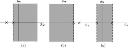
XX(s) = s+3/ (s+1) (s-2) = A/ s+1 + B/s-2
AA = -2/3 B = 5/3
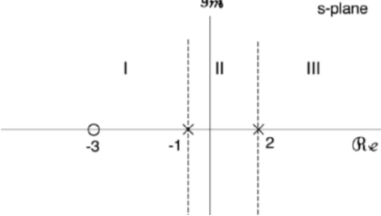
1/s + 1 = e-t
1/ s-2 = e 2t
All Laplace transforms in the above examples are rational, i.e., they can be written as a ratio of polynomials of variable  in the general form
X(s) = N(s) / D(s) =  s k /
s k /  s k =
s k =  k=1 M (s-szk)/ (s-spk)
- N(s) is the numerator polynomial of order M with roots szk(k=0,1,2…….M),
- D(s) is the denominator polynomial of order N with roots with spk =(1,2………N).
In general, we assume the order of the numerator polynomial is always lower than that of the denominator polynomial, M<N. If this is not the case, we can always expand X(s) into multiple terms so that M<N is true for each of terms.
Example:
X(s) = s2 – 2s + 2 / s3 + 5s2 + 12 s + 8
= s2 – 2s + 2 / (s+1) ( s2 + 4s + 8)
= [ s-(1+j)] [ s-(1-j)] / [ s-(-1)][s-(-2 + 2j) ][s-(-2 -2j)]
Two zeros: s1 = 1+j s2 = 1-j
Three poles sp1 = -1, sp2 = -2+2j and sp3 = -2 -2j
Key Takeaways:
- Representation of poles and zeros
Example:
X(s) = s2 -3/ s+2
As the order of the numerator M=2 is higher than that of denominator N=1 we expand the following terms
X(s) = s2 -3 / s+2 = A + Bs + C/ s+2
And get
s2 – 3 / s+2 = A + Bs + C/ s+2
And get
s2 – 3 = (A+Bs)(s+2) + C = B s2 + (A+2B ) s + (2A + C)
Equating the coefficients for terms s k k= 0,1……….M on both sides, we get
B=1, A +2B =0, 2A + C =-3
Solving this equation system, we get coefficients
A=-2, B=1, C=1.

Figure 4. RC network
In time-domain
At t=0 , v(0-) = 0
Therefore v(0) = 0 short circuit.

Figure 5. Short circuit
v(0+) = 1/C  ∂(x) dx = Io/C
The impulse current source has stored energy. ½ C ((v(0+)) 2 in capacitor as an initial voltage in an infinitesimal moment.
For t>0+ , ∂ (t) = 0 open circuit.
C dv/dt + v/R =0 natural response
v(0+) = Io/C
v(t) = Io/C e -t/τ u(t) , τ = RC

FFFigure 6. Open circuit
In s-domain

Figure7. RC circuit in s-domain
V(s) = Io R x 1/Cs / R + 1/Cs = Io/C / s + 1/RC
v(t) = Io/C e -t/τ u(t) ; τ = RC
Impulse caused by switching operation. The switch is closed at t=0 in the following circuit.

Figure 8. Capacitor circuit
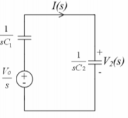
Figure 9. RC network
I(s) = Vo/s / 1/sC1 + 1/sC2 x Vo Ce
Ce = C1 . C2 / C1 + C2 ; V2(s) = Vo. Ce / sC2 = Vo/s . C1/C1 + C2
Therefore i(t) = Vo Ce ∂(t)
v2(t) = C1 / C1 + C2 Vo
At t=0 a finite charge of C1 is transferred to C2 instantaneously.
When the switch is closed the voltage across C2 does not jump to Vo of C1 but to its final value of the two paralleled capacitors.
Q2 = C2 V2 = C1.C2 / C1 + C2 Vo for t>0+
Q1 = C1 V2 = C1 2 / C1 + C2 . Vo ; t > 0+
Q1 + Q2 = c1 Vo ; t>0+
At t=0_ Q1 = C1 Vo; Q2 =0
Q1 + Q2 = C1 Vo
Conservation of charge.

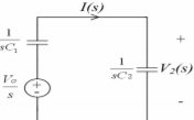
Figure 10. RC network
Key Takeaways:
Lapalce transform its representation t domain and s domain
Laplace transform can be used to solve (first‐ and second‐order) differential equations with constant coefficients. The differential equations must be IVP's with the initial condition (s) specified at x = 0.
Method:
For the given IVP apply Laplace transform to both the sides of the differential equation.
This will transform the differential equation to algebraic equation which is unknown.
F(p) is the Laplace transform of desired solution.
Solve the algebraic equation for F(p) and take inverse Laplace transform on bot sides to get the result which is the solution to the original IVP.
Solve the following IVP
y′′−10y′+9y=5t,y(0)=−1y′(0)=2y″−10y′+9y=5t,y(0)=−1y′(0)=2
The first step in using Laplace transforms to solve an IVP is to take the transform of every term in the differential equation.
L{y’’} – 10L {y’} + 9L{y} = L{5t}
s 2 Y(s) – s y(0) – y’(0) – 10 (sY(s) – y(0) ) + 9Y (s) = 5/ s 2
Plug in the initial conditions we get
(s 2 – 10s +9) Y(s) +s -12= 5/ s2
Solve for Y(s)
Y(s) = 5/ s2 (s-9) (s-1) + 12-s / (s-9) (s-1)
Combining the two terms we get
Y(s) = 5+12 s2 – s3 / s2 (s-9) (s-1)
The partial fraction decomposition for this transform is,
Y(s) = A/s + B/ s2 + C /s-9 + d/s-1
A = 50/81; B = 5/9 ; C= 31/81; D=-2
Taking inverse transform gives us
y(t) = 50/81 + 5/9 t + 31/81 e 9t – 2 et
Key Takeaways:
- Solution to the differential equation both for first order and second order
- To obtain the desired solution.
References:
1. A.V. Oppenheim, A.S. Willsky and I.T. Young, "Signals and Systems," Pearson, 2015.
2. R.F. Ziemer, W.H. Tranter and D.R. Fannin, "Signals and Systems - Continuous and Discrete," 4th edition, Prentice Hall, 1998.
3. B.P. Lathi, "Signal Processing and Linear Systems," Oxford University Press, 1998.
4. Douglas K. Lindner, "Introduction to Signals and Systems," McGraw Hill International Edition: 1999.
5. Simon Haykin, Barry van Veen, "Signals and Systems," John Wiley and Sons (Asia) Private Limited, 1998.
6. V. Krishnaveni, A. Rajeswari, “"Signals and Systems," Wiley India Private Limited, 2012.
7. Robert A. Gabel, Richard A. Roberts, "Signals and Linear Systems," John Wiley and Sons, 1995.
8. M. J. Roberts, "Signals and Systems - Analysis using Transform methods and MATLAB," TMH, 2003.
9. J. Nagrath, S. N. Sharan, R. Ranjan, S. Kumar, "Signals and Systems," TMH New Delhi, 2001.
10. A. Anand Kumar, “Signals and Systems,” PHI 3rd edition, 2018.
11. D. Ganesh Rao, K.N. Hari Bhat, K. Anitha Sheela, “Signal, Systems, and Stochastic Processes,” Cengage publication, 2018