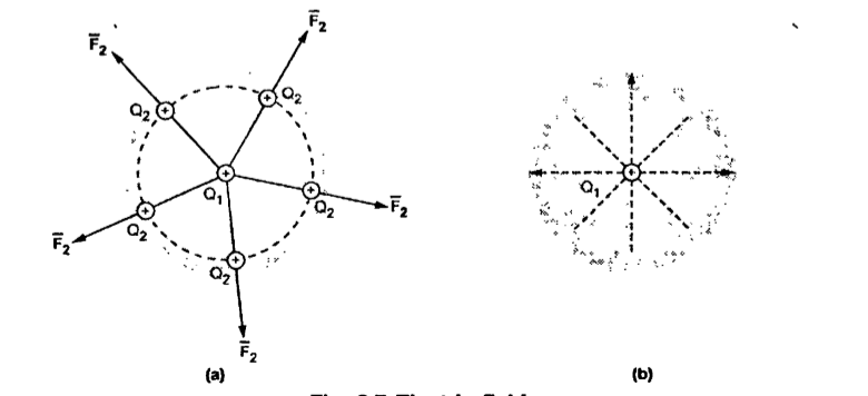
Consider a point charge Q1 as shown in figure:
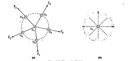
Figure 1. Electric field Intensity
If any other similar charge Q2 is brought near it Q2 experiences a force. Infact if Q2 is moved around Q1 still Q2 experiences a force as shown in figure.
Thus, there exists a region around a charge in which it exerts force on any other charge. This region where a particular charge exerts a force on any other charge located in that region called electric field of that charge . The electric field of Q1 is shown in figure (b).
The force experienced by the charge Q2 due to Q1 is given by Coulombs law as ,
 = Q1 Q2 / 4 π
  R2 12 .
Thus, force per unit charge can be written as:
 /Q2 = Q1 / 4 π
  R2 12 .
This force exerted per unit charge is called electric field intensity or electric field strength. It is a vector quantity and is directed along a segment from the charge Q1 to the position of any other charge.
It is denoted as  .
.
Another definition of electric field is the force experienced by a unit positive test charge that is Q2 = 1C.
Consider a charge Q1 as shown in figure below. The unit positive charge Q2=1C is placed at distance R from Q1. Then the force acting on Q2 due to Q1 is along the unit vector  As the charge Q2 is unit charge the force exerted on Q2 is nothing but electric field intensity
  of Q1. Then the force acting on Q2 due to Q1 is along the unit vector
  .As the charge Q2 is unit charge the force exerted onQ2 is nothing but electric field intensity
  of Q1 at a point where unit charge is placed.
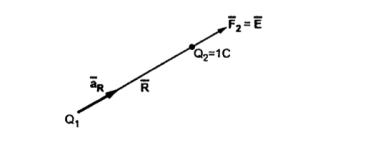
Figure 2. Concept of electric field intensity
 = Q1 / 4 π
  R2 .
R2 . 
If a charge Q1 is located at the centre of the spherical coordinate system then unit vector  in equation (3) becomes the radial unit vector
  coming radially outwards from Q1 and the distance R is the radius of the sphere r.
Key Takeaways:
The electric field intensity at any location is the force that would be experienced by unit test charge placed at the location.
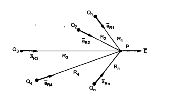
Consider n charges Q1,Q2,……..Qn as shown in figure . The combined electric field intensity is to be obtained at point P. The distances of point P from Q1,Q2……Qn are R1,R2,R3………Rn. The unit vectors along these directions are ,  ,
,  2,
2,  3……
3…… n.
n.
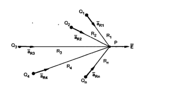
Figure 3. Electric field Intensity
Then the total electric field intensity at point P is the vector sum of the individual field intensities produced by various charges at the point P
 =
=  +
+  +
+  …………………. +
= Q1/ 4 π  R2 .
R2 .  + Q2/ 4 π
  R2 .
R2 .  + ……………+ Qn/4 π
  Rn2 .
Rn2 . 
 1/ 4 π
  / Ri 2
Each unit vector can be obtained by using the method discussed earlier
 =
=  -
-  / |
/ |  -
-  |
|
Where  = Position vector of point P
 = Position vector of point where charge Q1 is placed.
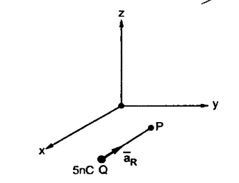
Determine the electric field intensity at P(-0.2,0,0,-2.3) m due to a point charge of +5nC at Q(0.2,0.1,-2.5)m in air.
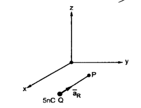
 = Q / 4 π
  R 2 .
R 2 . 
 =
=  / |
/ | 
=  -
-  / |
/ |  -
-  |
|
 -
-  = (-0.2 – 0.2)
  + (0 -0.1 )
  + [ -2.3 – (-2.5)]
= -0.4  – 0.1
– 0.1  + 0.2
+ 0.2 
 = -0.4
  – 0.1
– 0.1  + 0.2
+ 0.2  / √ (-0.4) 2 + (0.1) 2 + (0.2) 2
= -0.4  – 0.1
– 0.1  + 0.2
+ 0.2  / 0.45825
= -0.8728  – 0.2182
  + 0.4364
R = | -
-  | = 0.45825
 = 5 x 10 -9 / 4
  x 8.854 x 10 -12 x (0.45825) 2 [
 ] = 214
Substituting value of 
 = -186.779
  – 46.694
  + 93.389
  V/m
V/m
This is electric field intensity at point P.
Key Takeaways:
The electric field intensity at any point is the strengtb of electric field at that point . It is defined as the force experienced by unit positive charge placed at a particular point.
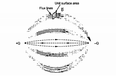
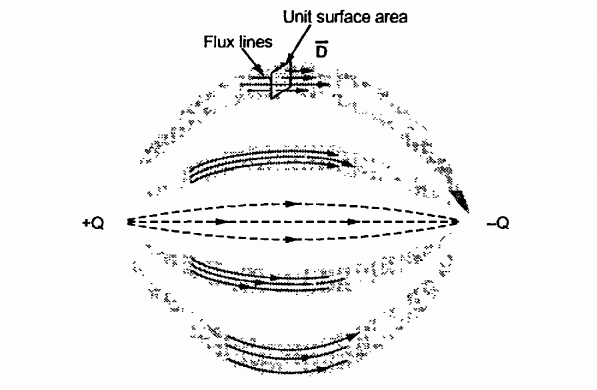
Figure 4. Electric flux density
Consider a unit surface area as shown in figure. Te number of flux lines are passing through this surface area.
The net flux passing normal through the unit surface area is called electric flux density. It is denoted as  . It has specific direction normal to the surface area under consideration hence it is a vector field.
Consider a sphere with a charge Q placed at the centre. There are no other charges present around. The total flux distributes around the charge is  = Q. This flux distributes uniformly over the surface of the sphere.
 = Total flux
While S = Total surface area of sphere.
The electric flux density is defined as
D =  / S in magnitude.
Definition:
The total charge enclosed by the irregular closed surface is Q coulombs. Hence the total flux has to pass through the closed surface is Q. Consider a small differential surface dS at point P. As the surface is irregular the direction of D as well as its magnitude is going from point to point on the surface. The surface dS under consideration can be represented in vector form.
d  = d S
= d S 
where  = Normal to the surface d at point P
The flux density at point P is D and its direction is such that it makes an angle Ѳ with the normal direction at point P.
The flux d passing through the surface dS is the product of the component normal to dS and d
 .
.
Mathematically thus can be represented as,
d  = Dn dS
Dn = component of  in the direction of normal to the surface dS
From the figure we can write
Dn = | | cos
| cos 
d  = |
= | | cos
| cos  dS
dS
From the definition of the dot product
 .
.  = |A| |B| cos ƟAB
| | cos
| cos  dS =
dS =  d
d 
This is the flux passing through incremental surface area dS. Hence the total flux passing through the entire closed surface is to be obtained by finding the surface integration of the equation
 =
= 
 =
= 
 sign indicates the integration over the closed surface called closed surface integral.
Such a closed surface over which the integration in eq(6) is carried out is called Gaussian surface.
Total charge enclosed by the surface is given by
 =
=  = Q = Charge enclosed.
Applications:
Infinite line charge:
Consider an infinite line charge of density  C/m lying along the z-axis from -
  to
to  as shown in figure.
Consider the Gaussian surface as the right circular cylinder with z-axis as its axis and radius r as shown in figure. The length of the cylinder is L.
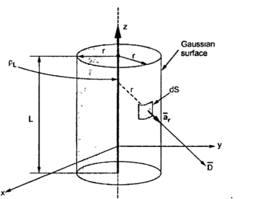
Figure 5. Infinite Line charge
The flux density at any point on the surface is directed radially towards that is in the  direction according to cylindrical co-ordinate system.
Consider differential surface area dS as shown which is at a radial distance r from the line charge. The direction is normal to dS is 
As the line charge is along z-axis there cannot be any component D in z direction. So D has only radial component.
Now Q =  . d
. d 
The integration is to be evaluated for side surface, top surface and bottom surface
Q =  . d
. d  +
+  . d
. d  +
+  . d
. d 
 = Dr
= Dr  as has only radial component
d  = r dɸ dz
  normal to
  direction
 . d
. d  = D r r dɸ dz (
  .
.  = D r r dɸ dz
D r is constant over the side surface.
As  has only radial component and no component along
  and -
and -  hence integrations over top and bottom surfaces is zero.
 . d
. d  =
=  . d
. d 
Q =  . d
. d  =
=  r dɸ dz
=  r dɸ dz = r Dr [ z] 0 L [ ɸ] 0 2π
Q = 2  r Dr L
Dr = Q / 2  r L
r L
 = Dr
= Dr  = Q / 2
  r L .
r L . 
Q/L =  / 2
/ 2  r .
r . 
 =
=  /
/  = =
= =  / 2
/ 2  r .
r .  V/m
V/m
Key Takeaways:
Gauss Law states that the total electric flux out of a closed surface is equal to the charge enclosed divided by the permittivity.
2.4.1 Maxwells equations
The divergence of electric flux density  is given by
div  = lim ∆v->0
  . d
. d  / ∆v --------------------(1)
 Dx/
Dx/  +
+  Dy /
Dy /  y +
y +  Dz/∂z -------------------------(2)
According to Gauss’s law it is known that
 = Q =
= Q =  . d
. d  -----------------------------------------------(3)
Expressing Gauss’s law per unit volume basis
Q/ ∆v =  . d
. d  / ∆v -----------------------------------------(4)
Taking lim ∆v->0 volume shrinks to zero
lim ∆v->0 Q/ ∆v = lim ∆v->0  . d
. d  / ∆v
/ ∆v
But lim ∆v->0 Q/ ∆v =  at that point-----------------------(5)
This equation gives the volume charge density at the point where divergence is obtained.
Equating (1) and (5)
div  =
=  -------------------------------(6)
 .
.  =
= 
This is volume charge density around a point. The equation (6) is called Maxwells first equation.
The current Iout coming out of the closed surface
I out =  . dS = - d Qin/dt
Where Qin is the total charge enclosed by the closed surface. Using diverhgence theorem
 . dS =
  . J dv
But
-d Qin/dt = -d/dt  dv = -
  /dt dv--------------------(i)
Equation (i) now becomes
 . J dv = -
  /dt dv
Or
 . J = - ∂
  / ∂t
/ ∂t
This is called continuity of current equation.
According to Ohms law
J =  E
E
According to Gauss law
 =
=  /
/  --------------------------------(ii)
 =
=  /
/  = - ∂
= - ∂  /
/ 
Or
∂  / ∂t +
  /
/  =0
=0
This is homogeneous linear ordinary differential equation. By separating variables, we get
∂  /
/  =
=  /
/  ∂t
∂t
Integrating both sides
ln  = -
= -  /
/  + ln
+ ln  vo where
  vo is constant of integration.
Where
 =
=  vo e -t/Tp
Tr =  /
/ 
The time constant Tr is known as the relaxation time or the relaxation time.
Depending on the nature of the media there are two situations of boundary conditions:
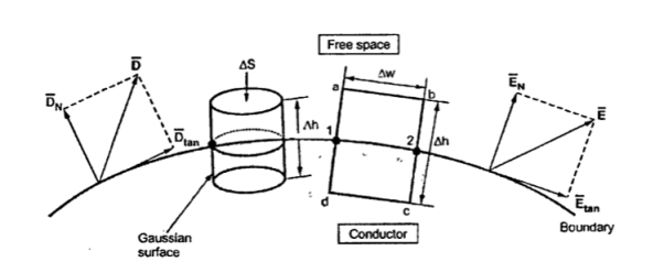
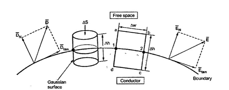
Figure 6. The boundary between conductor and free space.
The field intensity inside the conductor is zero and flux density inside a conductor is zero.
No charge can exist within a conductor. The charge appears on the surface in the form of surface charge density.
The charge density within the conductor is zero.
Thus  ,
,  and
and  within the conductor
  is zero is the surface charge density.
In order to determine the boundary conditions, use the closed path and Gaussian surface.
 at the boundary.
Let  be the electric field intensity in the direction making some angle with the boundary. This
  is resolved into two components
The component tangential to the surface
The component normal to the surface.
 . d
. d  = 0 ------------------------(1)
The integral  . d
. d  of carried over a closed contour is zero that is the work done in carrying unit positive charge along the closed path is zero.
Consider a rectangular closed path abcda as shown in figure. It is traced in clockwise direction hence  . d
. d  is divided into four parts:
 . d
. d  =
=  . d
. d  +
+  . d
. d  +
+  . d
. d  +
+  . d
. d  =0 ---------(2)
The closed contour is placed in such a way that its two sides a-b and c-d are parallel to tangential direction to the surface while the other two are normal to the surface at the boundary.
The rectangle with height  and width
  is placed in a manner that half of it is conductor and remaining half is free space. Thus
  is in the conductor and
in free space.
The portion of c-d in conductor where  hence the corresponding integral is zero.
 . d
. d  +
+  . d
. d  +
+  . d
. d  =0
=0
The width  therefore E is constant hence,
 . d
. d  =
= 
 =
= 
 =
=  (
( w) ---------------------(4)
But  is tangential to the boundary hence
  =
=  tan (∆w)
 . d
. d  = E tan (∆w) where Etan = | E tan| ---------------(5)
Now b-c is parallel to the normal component therefore  =
=  N along this direction. Let
EN = |EN|
For small height  EN is assumed constant and taken out of integration.
 . d
. d  =
= 
 = EN
= EN  ----------------(6)
But out of b-c , b-2 is in free space and 2-c is in the conductor when  =0
=0
 =
=  +
+  = ∆h/2 + 0 = ∆h/2 ----------------(7)
 = EN (∆h/2) -------------------(8)
For path d-a the condition is same as for b-c only direction is opposite.
 .
.  = -EN (∆h/2)
Substituting eq 4 and 8 and 3 and 9 we get
Etan ∆w + EN (∆h/2) - EN (∆h/2) = 0
Etan ∆w =0
E tan =0
Thus, the tangential component of the electric field intensity is zero at the boundary between conductor and free space.
Problem:
a) V b) c) Et d) EN e)
  f) DN g)
At P , x=0.1 , y=  z =
z =  / 24.
/ 24.
V = 100 e – 0.5 sin 3 / 12 cos 4
 / 24 = 37.1422 V
 = -
= -  V ( ∂Vx/∂x
  + ∂ Vy/ ∂ y
  + ∂ Vz/ ∂ z
= -100[-5 e 5x sin 3y cos 4z  + e -5x (3) (cos3y)(cos 4z)
  + e-5x (sin 3y) (4) (-sin 4z)
At P
 = [-100[-1.857
  - 1.114
  + 85.776
  ]= 185.7
  -111.4
  + 85.776
|E| = 232.9206 V/m
c ) Et = 0 V/m P is on the boundary.
d ) EN = | | = 232.9206 V
e )  = 8.854 x 10 -12 [185.7
  -111.4
  + 85.776
  ]
]
 = 1.992 nC /m2
DN = | |= 1.992 nC /m2
DN =  1.992 nC / m2
Magnetostatics is the subfield of electromagnetics describing a static magnetic field, such as the one generated by a steady electric current or a permanent magnet. Starting with free space, the equations of magnetostatics are Gauss's magnetic law:

and Maxwell–Ampère's law (static version):
where 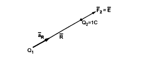 is the magnetic flux density,
  is the current density, and
  is the permeability of vacum.
Note that the magnetic version of Gauss's law implies that there are no magnetic charges. A further consequence of this law is that the magnetic flux density is solenoidal, or divergence free. This means that the field can be written as the curl of another vector field as follows:
where the field 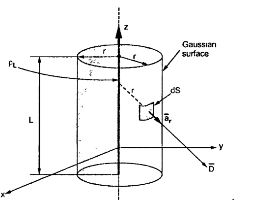 is called the magnetic vector potential.
It states that
The line integral of magnetic field intensity  around closed path is exactly equal to direct current enclosed by that path.
The mathematical representation of Ampere’s circuital law is
 .
.  = I ----------------------------------(1)
This law is useful to determine  when current distribution is symmetrical.
Proof:
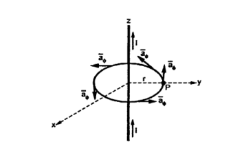
Figure . Conductor
Consider a long straight conductor carrying direct current I placed along z axis as shown in figure. Consider a closed circular path of radius r which encloses the straight conductor carrying direct current I. The point P is at perpendicular distance r from the conductor.
Consider  at point P which is direction
  direction tangential to circular path at point P.
Therefore,
 = r dɸ
  ------------------------------(2)
While  obtained at point P, from Biot-Savart law due to infinitely long conductor is,
 = 1/2πr .
  ---------------------------------(3)
 .
.  = 1/2πr .
  + r dɸ
= 1/2πr . r dɸ = 1/2π dɸ
Integrating  .
.  over the entire closed path
 .
.  =
=  dɸ = 1/2π [ɸ] 0 2π
= I 2π/2π
This proves that the integral  .
.  along closed path gives the direct current enclosed by that closed path.
Steps to Apply Amper’s Circuital Law:
Step1: Consider a closed path preferably symmetrical such that it encloses the direct current I once. This is Amperian path.
Step2: Consider differential length  depending upon the co-ordinate system used.
Step3: Identify the symmetry and find in which direction  exists according to co-ordinate system used.
Step 4: Find  . Make sure that
  and
and  are in the same direction.
Step 5: Find the integral of  .
.  around the closed path. And equate it to current I enclosed by the path.
To apply Ampere’s circuital law the following conditions must be satisfied,


Consider Ampere's law for the usual infinitely long wire carrying a steady current I, but now break the wire at some point and put in two large circular metal plates, a capacitor, maintaining the steady current I in the wire everywhere else, so that charge is simply piling up on one of the plates and draining off the other.
Looking now at the wire some distance away from the plates, the situation appears normal, and if we put the usual circular path around the wire, application of Ampere's law tells us that the magnetic field at distance r, from
 =μ0I
=μ0I
is just
B=μ0I/2πr.
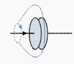
Figure 8. Parallel plates
Assuming the plates are close together, we can take all the electric field lines from the charge q on one plate to flow across to the other plate, so the total electric flux across the surface between the plates,
 .
.  = q/
= q/
Now, the current in the wire, I, is just the rate of change of charge on the plate,
I=dq/dt.
Putting the above two equations together, we see that
I=d/dt(ε0 .  .
.  )
)
Ampere's law can now be written in a way that is correct no matter where we put the surface spanning the path we integrate the magnetic field around:
 = μo( I + d/dt (ε0 .
  .
.  ))
))
This is Maxwell’s fourth equation.
In Electrostatics, electric field E is derivable from the electric potential V.
 x E = 0
 = -
= -  V
V
V is a scalar quantity and easier to handle than E which is a vector quantity. In Magnetostatics, the quantity Magnetic scalar potential can be obtained using analogues relation
 x B =
x B = 
In regions of space in the absence of currents, the current density j =0
 x B =0
B is derivable from the gradient of a potential Therefore B can be expressed as the gradient of a scalar quantity φm B = - ∇φm φm is called as the Magnetic scalar potential.
The magnetic scalar potential is useful only in the region of space away from free currents. If J=0, then only magnetic flux density can be computed from the magnetic scalar potential The potential function which overcomes this limitation and is useful to compute B in region where J is present is . Magnetic Vector Potential
Figure 9. Charge density
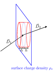
Consider the electric displacement at a boundary between two different materials. To be completely general, we will assume that there is some surface charge density ρs (charge per unit area) on the boundary. Applying Gauss’ theorem to the divergence of the electric displacement, integrated over a pillbox crossing the boundary.
Take Maxwell’s equation: ∇ · D~ = ρ (1)
Integrate over the volume of the pillbox, and apply Gauss’ theorem:

 dV =
dV =  =
=  dV -------------------------------------------(2)
Taking the limit in which the height of the pillbox becomes zero. If the flat ends of the pillbox have (small) area A, then:
− D1nA + D2nA = ρsA
Dividing by the area A, we arrive at: D2n − D1n = ρ
Now consider the magnetic intensity at a boundary between two different materials
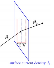
Figure 10. Current density
Assume that there is some surface current density J~s (current per unit length) on the boundary. On applying Stokes’ theorem to the curl of the magnetic intensity, integrated over a loop crossing the boundary.
Take Maxwell’s equation:
 x
x  =
=  +
+ 
 /
/  t ---------------------------------------------------(5)
Integrate over the surface bounded by the loop, and apply Stokes’ theorem to obtain:
 x
x  .
.  =
=  .
.  =
=  x
x  .
.  + ∂ / ∂t
  .
.  ---------(6)
Now take the limit where the lengths of the narrow edges of the loop become zero:

where Js⊥ represents a surface current density perpendicular to the direction of the tangential component of H~ that is being matched
Boundary conditions on the normal component of the magnetic field B~ , and on the tangential component of the electric field E~ can be obtained using the same arguments.
The total flux of electric field out of a closed surface is just the total enclosed charge multiplied by 1/ε0,
 .
.  = q/
= q/ 
This is Maxwell’s first equation. It represents completely covering the surface with a large number of tiny patches having areas 
The second Maxwell equation is the analogous one for the magnetic field, which has no sources or sinks that is no magnetic monopoles, the field lines just flow around in closed curves. Thinking of the force lines as representing a kind of fluid flow, the so-called "magnetic flux",
 .
.  = 0
= 0
The simplest version of Maxwell's third equation is the electrostatic case:
The path integral  ⋅
⋅  for electrostatics.
However, we know that this is only part of the truth, because from Faraday's Law of Induction, if a closed circuit has a changing magnetic flux through it, a circulating current will arise, which means there is a nonzero voltage around the circuit.
The full version of Maxwell's third equation is:
 ⋅
⋅  = -d/dt (
 .
.  )
)
References:


