Unit - 5
Fibre Optics & Laser
OPTICAL FIBRE
A cable which is used to transmit the data through fibres (threads) or plastic (glass) is known as optical fibre cable. This cable includes a pack of glass threads which transmits modulated messages over light waves.
Principle: Optical Fibre works on the principle of Total Internal Reflection.
Total internal reflection:
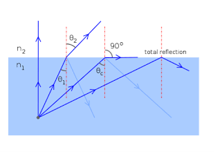
When the light ray travels from denser medium to rarer medium the refracted ray bends away from the normal. When the angle of incidence is greater than the critical angle, the refracted ray again reflects into the same medium. This phenomenon is called total internal reflection. The refracted ray bends towards the normal as the ray travels from rarer medium to denser medium. The refracted ray bends away from the normal as it travels from denser medium to rarer medium.
|
Figure – Total Internal Reflection
CHARACTERISTICS OF OPTICAL FIBRE
- It has a large bandwidth.
- The optical frequency of 2 x 10¹⁴ Hz can be used and hence the system has higher bandwidth.
- Thus optical fibres have greater information-carrying capacity due to greater bandwidth.
- In optical fibre system transmission losses are as low as 0.1 db/km.
- Optical fibre is of small size and light weight as compared to electrical fibre.
- Optical fibre communication is free from electromagnetic interference.
- Optical fibre does not carry high voltage and current hence they are safer than electrical cable.
- Optical Fibres are flexible and have high tensile strength. Thus can be bent or twisted easily.
|
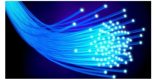
Figure: Optical Fibre
CONSTRUCTION OF OPTICAL FIBRE
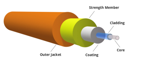
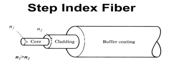
It consists of a very thin fibre of silica or glass or plastic of a high refractive index called the core. The core has a diameter of 10 um to 100 um. The core is enclosed by a cover of glass or plastic called cladding. The refractive index of the cladding is less than that of the core (which is a must condition for the working of the optical fibre). The difference between the two indicates is very small of order 10-3. The core and the cladding are enclosed in an outer protective jacket made of plastic to provide strength to the optical fibre. The refractive index can change from core to cladding abruptly (as in step-index fibre) or gradually (as in graded-index fibre).
|
Figure Representation of Optical Fibre
WORKING OF OPTICAL FIBRE
When a ray of light is incident on the core of the optical fibre at a small angle, it suffers refraction and strikes the core-cladding interface, As the diameter of the fibre is very small hence the angle of incidence is greater than the critical angle. Therefore, the ray suffers total internal reflection at the core-cladding interface and strikes the opposite interface. At this interface also, the angle of incidence is greater than the critical angle, so it again suffers total internal reflection. Thus, the ray of light reaches the other end of the fibre after suffering repeated total internal reflections along the length of the fibre. At the other end, the ray suffers refraction and emerges out the optical fibre.
We can see that the light travels in the core in a guided manner. Hence the communication through the optical fibre is sometimes referred as an optical waveguide.
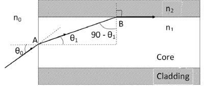
ACCEPTANCE ANGLE Definition: - Acceptance angle is defined as the maximum angle of incidence at the interface of air medium and core medium for which the light ray enters into the core and travels along the interface of core and cladding. Let n0 be the refractive indices of air n1 be the refractive indices of core n2 be the refractive indices of cladding
Let a light ray OA is incident on the interface of air medium and core medium with an angle of incidence θ0 The light ray refracts into the core medium with an angle of refraction θ1 and the refracted ray AB is again incidenting on the interface of core and cladding with an angle of incident (90- θ1) If (90- θ1) is equal to the critical angle of core and cladding media then the ray travels along the interface of core and cladding along the path BC. If the angle of incident at the interface of air and core θ1< θ0 then (90- θ1) will be greater than the critical angle. Therefore, The total internal reflection takes place. According to Snell’s law at point A n0 Sin θ0 = n1 Sin θ1 Sin θ0= (n1 / n0) Sin θ1 ………(1) According to Snell’s law at point B n1 Sin(90- θ1) = n2 Sin90 ………(2) n1 Cosθ1 = n2 as (Sin90=1) Cosθ1 = n2 /n1 Sinθ1 = (1-Cos2 θ1)1/2 Sinθ1= (1- (n2 /n1)2)1/2 Sinθ1= ( n12- n22 )1/2/ n1 ………(3) We know Sin θ0= (n1 / n0) Sin θ1 from equation (1) Substitute the value of Sinθ1 from equation (3) Sinθ0= (n1 / n0) *( n12- n22 )1/2/ n1 On simplification Sinθ0= ( n12- n22 )1/2/ n0 θ0=Sin-1 ( n12- n22 )1/2/ n0 Acceptance Angle is θ0=Sin-1 ( n12- n22 )1/2/ n0 ………(4)
NUMERICAL APERTURE Definition: -Numerical aperture is defined as the light gathering capacity of an optical fibre and it is directly proportional to the acceptance angle. Numerically it is equal to the sin of the acceptance angle. NA = Sin(acceptance angle) NA = Sin {Sin-1 (( n12- n22 )1/2/ n0)} from equation (4) NA = (( n12- n22 )1/2/ n0) ………(5) If the refractive index of the air medium is unity i.e. n0=1 put in (5) NA = ( n12- n22 )1/2 ………(6) Fractional change in refractive index ∆= (n1- n2)/ n1 n1∆ = (n1- n2) ………(7) from equation (6), we have NA = {( n1- n2 )( n1+n2 )}1/2 NA = { n1∆ (n1+n2 )}1/2 as n1∆ = (n1- n2) by Eq(7) NA = { n1∆ 2n1}1/2 n1 ≈ n2, so n1+n2 =2n1 NA = n1{2∆}1/2 This gives the relation between Numerical aperture and Fractional change in refractive index.
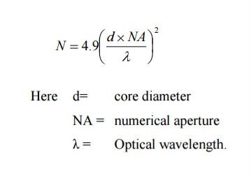
NORMALIZED FREQUENCY Or V-NUMBER V – number determines how many modes a fiber can support, It is given by, V = Where d is the diameter of the core, l is the wavelength of light used NA is the numerical aperture of the fibre. V = Or V = If V ≤ 2.405, then the fibre is single mode fibre (SMF)
If V > 2.405, then the fibre is multimode fibre (MMF) Example: Consider a multimode step index fibre with n1 = 1.53 and n2 = 1.50 and λ= 1μm. If the core radius = 50 μm then calculate the normalized frequency of the fibre (V) and the number of guided mode. Solution: d = 2r = 2 x 50 x 10-6 m V = =94.72= normalized frequency Total number of guided mode = M = V2/2 = 4486. |
The types of optical fibres depend on the refractive index, materials used, and mode of propagation of light.
The classification based on the materials used is as follows:
- Plastic Optical Fibres: The polymethylmethacrylate is used as a core material for the transmission of the light.
Example:
Core: polymethyl methacrylate : Cladding: Co- Polymer
Core: Polystyrene : Cladding: Methyl methacrylate
- Glass Fibres: It consists of extremely fine glass fibres.
Example:
Core: SiO2 Cladding: SiO2
Core: GeO2- SiO2 Cladding: SiO2
The classification based on the mode of propagation of light is as follows:
Mode of propagation:
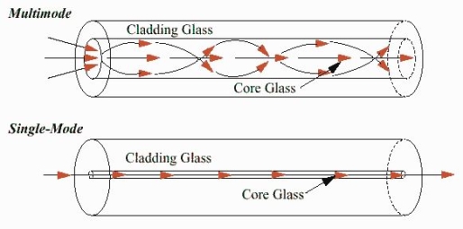
Light propagates as electromagnetic waves through an optical fibre. All waves, having ray directions above the critical angle will be trapped within the fibre due to total internal reflection. However, all such waves do not propagate through the fibre. Only certain ray directions are allowed to propagate. The allowed directions correspond to the modes of the fibre. In simple terms, modes can be visualized as the possible number of paths of light in an optical fibre.
- Single-Mode Fibres:
These fibres are used for long-distance transmission of signals. In general, the single mode fibres are step – index fibres. These types of fibres are made from doped silica. It has a very small core diameter so that it can allow only one mode of propagation and hence called single mode fibres.
The cladding diameter must be very large compared to the core diameter. Thus in the case of single mode fibre, the optical loss is very much reduced. The structure of a single mode fibre is given below.
Structure:
Core diameter : 5-10μm
Cladding diameter : Generally around 125μm
Protective layer : 250 to 1000μm
Numerical aperture : 0.08 to 0.10
Band width : More than 50MHz km.
Application:
Because of high bandwidth, they are used in long haul communication systems.
|
2. Multimode Fibres:
These fibres are used for short-distance transmission of signals. The multi-mode fibres are useful in manufacturing both for step – index and graded index fibres. The multi-mode fibres are made by multi-component glass compounds such as Glass – Clad Glass, Silica – Clad – Silica, doped silica etc. Here the core diameter is very large compared to single mode fibres, so that it can allow many modes to propagate through it and hence called as Multi mode fibres. The cladding diameter is also larger than the diameter of the single mode fibres. The structure of the multimode fibre is as shown in the figure above.
Structure: Core diameter : 50-350μm Cladding diameter : 125μm - 500μm Protective layer : 250 to 1100μm Numerical aperture : 0.12 to 0.5 Band width : Less than 50MHz km. The total number of modes possible for such an electromagnetic wave guide is
|
Application:
Because of its less band width it is very useful in short haul communication systems.
The classification based on the refractive index is as follows:
- Step Index Single mode Fibres
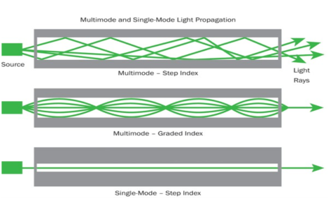
It consists of a core surrounded by the cladding, which has a single uniform index of refraction. Step index-single mode fibres: A single mode step index fibre consists of a very thin core of uniform refractive index surrounded by a cladding of refractive index lower than that of core. The refractive index abruptly changes at the core cladding boundary. Light travels along a side path, i.e., along the axis only. So zero order modes is supported by Single Mode Fibre.
|
- Step index-Multimode fibres
A multimode step index fibre consists of a core of uniform refractive index surrounded by cladding of refractive index lower than that of the core. The refractive index abruptly changes at the core cladding boundary. The core is of large diameter. Light follows zigzag paths inside the fibre. Many such zigzag paths of propagation are permitted in Multi-Mode Fibre. The Numerical Aperture of a Multi-mode fibre is larger as the core diameter of the fibre is larger
|
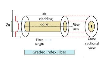
- Graded Index Fibres:
The refractive index of the optical fibre decreases as the radial distance from the fibre axis increases. GRIN fibre is one in which refractive index varies radially, decreasing continuously in a parabolic manner from the maximum value of n1, at the center of the core to a constant value of n2 at the core cladding interface.
In graded index fibre, light rays travel at different speeds in different parts of the fibre because the refractive index varies throughout the fibre. Near the outer edge, the refractive index is lower. As a result, rays near the outer edge travel faster than the rays at the center of the core. Because of this, rays arrive at the end of the fibre at approximately the same time. In effect light rays arrive at the end of the fibre are continuously refocused as they travel down the fibre. All rays take the same amount of time in traversing the fibre. This leads to small pulse dispersion.
|
|
For a parabolic index fibre, the pulse dispersion is reduced by a factor of about 200 in comparison to step index fibre. It is because of this reason that first and second generation optical communication systems used near parabolic index fibres.
Attenuation in Optical Fibres
- Attenuation is a measure of decay of signal strength or loss of light power that occurs as light pulses propagate through the length of the fibre
- In optical fibres the attenuation is mainly caused by two physical factors absorption and scattering losses. Absorption is because of fibre material and scattering due to structural imperfection within the fibre.
- Nearly 90 % of total attenuation is caused by Rayleigh scattering only. Micro bending of optical fibre also contributes to the attenuation of signal.
- The rate at which light is absorbed is dependent on the wavelength of the light and the characteristics of particular glass. Glass is a silicon compound; by adding different additional chemicals to the basic silicon dioxide the optical properties of the glass can be changed.
- The Rayleigh scattering is wavelength dependent and reduces rapidly as the wavelength of the incident radiation increases.
- The attenuation of fibre is governed by the materials from which it is fabricated, the manufacturing process and the refractive index profile chosen.
- Attenuation loss is measured in dB/km.
As attenuation leads to a loss of power along the fibre, the output power is significantly less than the couples power. Let the couples optical power is P(0) i.e. at origin (z =0).Then the power at distance z is given by, P(z) = P(0) Where, αp is fibre attenuation constant (per km). αp = αp (dB/km ) = 10. αp (dB/km ) = 4.343 αp/km
This parameter is known as fibre loss or fibre attenuation. Attenuation is also a function of wavelength.
Example: When mean optical power launched into an 8 km length of fibre is 12 μW, the mean optical power at the fibre output is 3 μW. Determine a) Overall signal attenuation in dB. b) The overall signal attenuation for a 10 km optical link using the same fibre with splices at 1 km intervals, each giving an attenuation of 1 dB.
Solution: Given :z=8km P(0) = 120 μW P(z) = 3 μW
a) Overall attenuation is given by,
αp (dB/km ) = 10. log
b) Overall attenuation for 10 km, Attenuation per km = αp (dB/km ) = = Attenuation in 10 km link = 2.00 x 10 = 20 dB In 10 km link there will be 9 splices at 1 km interval. Each splices introducing attenuation of 1 dB. Total attenuation = 20 dB + 9 dB = 29 dB
Dispersion in Optical Fibres Dispersion: A light pulse launched into a fibre decreases in the fibre. It also spreads during its travel. The pulse received at the output is wider than input pulse. It means that the pulse becomes distorted as it is propagated through the fibre. Such a distortion arises due to dispersion effects. Dispersion is typically measured in Nano seconds per kilometre (ns/km). There are three mechanisms which contribute to the distortion of the light pulse in a fibre. They are known as:
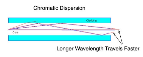
Material dispersion is also called as chromatic dispersion. Material dispersion exists due to change in index of refraction for different wavelengths. A light ray contains components of various wavelengths. The time delay is different for different wavelength components. This results in time dispersion of pulse at the receiving end of fibre. Light waves of different wavelengths travel at different speeds in a medium. The short wavelength waves travel slower than long wavelength waves. Consequently, narrow pulses of light tend to broaden as they travel down the optical fibre. This is known as material dispersion.
The material dispersion for unit length (L = 1) is given by
D =
Where c = Light velocity λ = Center wavelength
Negative sign shows that the upper sideband signal (lowest wavelength) arrives before the lower sideband (highest wavelength).
The unit of dispersion is : ps/nm/km. The amount of material dispersion depends upon the chemical composition of glass.
Example: An LED operating at 850 nm has a spectral width of 45 nm. What is the pulse spreading in ns/km due to material dispersion? Solution: Given :λ = 850 nm σ = 45 nm R.M.S pulse broadening due to material dispersion is given by, σm= σLM Considering length L = 1 metre Dmat = For LED source operating at 850 nm, M = M = 9.8 ps/nm/km σm= 441 ns/km
τwg =
Where, b = Normalized propagation constant k = 2π / λ (group velocity) Normalized frequency V, V = ka τwg = The second term As frequency is a function of wavelength, the group velocity of the energy varies with frequency. This produces additional losses (waveguide dispersion). The propagation constant (b) varies with wavelength, the causes of which are independent of material dispersion.
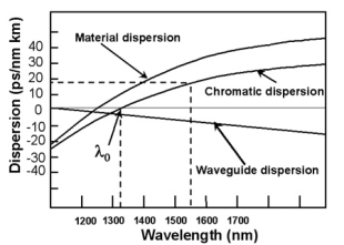
The combination of material dispersion and waveguide dispersion is called chromatic dispersion. These losses primarily concern the spectral width of transmitter and choice of correct wavelength.
Material dispersion and waveguide dispersion effects vary in opposite senses as the wavelength increased, but at an optimum wavelength, two effects almost cancel each other and chromatic dispersion is at minimum. Attenuation is therefore also at minimum and makes highly attractive Operating wavelength.
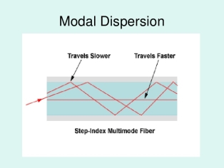
As only a certain number of modes can propagate down the fibre, each of these modes carries the modulation signal and each one is incident on the boundary at a different angle, they will each have their own individual propagation times. The net effect is spreading of pulse; this form o dispersion is called modal dispersion.
∆tmodal =
Where ∆tmodal = Dispersion n1= Core refractive index Z = Total fibre length c = Velocity of light in air. The above equation can also be written as ∆tmodal = The modal dispersion ∆tmodal describes the optical pulse spreading due to modal effects optical pulse width can be converted to electrical rise time through the relationship. tr mod = 0.44 (∆tmodal)πr2
ADVANTAGES OF FIBRE OPTIC COMMUNICATION
The optical fibre communication has more advantages than convectional communication. 1. Enormous Bandwidth 2. Low Transmission Loss 3. Electric Isolation 4. Signal Security 5. Small Size and Less Weight 6. Immunity Cross Talk
1. Enormous bandwidth:- The information carrying capacity of a transmission system is directly proportional to the frequency of the transmitted signals. In the coaxial cable transmission, the bandwidth range is up to around 500MHz only. Where as in optical fibre communication, the bandwidth range is large as 105 GHZ.
2. Low transmission loss:- The transmission loss is very low in optical fibres (i.e.KmdB/2.0) than compare with the conventional communication system. Hence for long distance communication fibres are preferred.
3. Electric isolation:- Since fibre optic materials are insulators, they do not exhibit earth and interface problems. Hence communicate through fibre even in electrically danger environment.
4. Signal security:- The transmitted signal through the fibre does not radiate, unlike the copper cables, a transmitted signal cannot be drawn from fibre without tampering it. Thus the optical fibre communication provides 100% signal security.
5. Small size and less weight:- The size of the fibre ranges from 10μm to 50μm, which is very small. The space occupied by the fibre cable is negligibly small compared to conventional electrical cables. Optical fibres are light in weight.
6. Immunity cross talk:- Since the optical fibres are dielectric wave guides, they are free from any electromagnetic interference and radio frequency interference. Since optical interference among different fibres is not possible, cross talk is negligible even many fibres are cabled together.
DISADVANTAGES OF OPTICAL FIBRE The disadvantages of optical fibre include the following
APPLICATION OF OPTICAL FIBRE
|
Introduction
LASER stands for “Light Amplification by Stimulated Emission of Radiation” .
L = Light
A = Amplification (by)
S = Stimulated
E = Emission (of)
R = Radiation
Theodore H. Maiman of the Hughes Research Laboratory, California, was the first scientist who experimentally demonstrated laser by flashing light through a ruby crystal in 1960. But the basic idea behind the development of laser was given by the great scientist “Albert Einstein” in his 1917.
Properties of Laser
- Laser is a powerful source of light having extraordinary properties which are not found in the normal light sources like tungsten lamps, mercury lamps etc.
- The unique property of laser is that its light waves travel very long distances with e very little divergence. whereas conventional source of light can travel very short distances only.
- A high degree of directionality and monochromatic is also associated with these laser light beams. Therefore, in a laser beam the light waves not only are in the same phase but also have the same colour throughout their journey.
- The beam of the ordinary light spreads out very quickly. On the other hand, the laser beam is highly collimated and spreads very little.
- The spread of laser light on the surface of the moon has been found to be only about 3 km across. Hypothetically, if ordinary light was able to travel to the so moon, its beam would have fanned out to such an extent leading to a diameter of the light on the moon as much as 40, 000 km.
- Another remarkable feature of laser is the concentration of its energy to extremely high intensities, the intensity remaining almost constant over long distances because of low divergence.
- If a laser beam with a power of a few megawatts is focused by a lens at a spot with a diameter of 1/1000th of a centimeter. the beam intensity increases to a few hundred billion watts per sq. cm. This concentrated energy is so intense that it easily ionizes the atmospheric air to create sparks. When the beam focused from a high power laser, even the hardest material like diamond can be melted in a fraction of a second.
ABSORPTION OF RADIATION, SPONTANEOUS AND STIMULATED EMISSION OF RADIATION
Let us discuss Einstein’s theory of interaction of electromagnetic radiation with matter. He proposed that electromagnetic radiation interacts with matter in following three steps.
- Stimulated Absorption
- Spontaneous Emission
- Stimulated Emission
Stimulated Absorption:
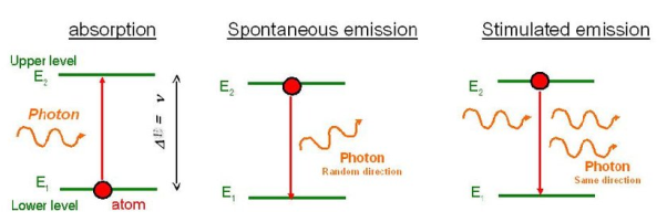
Let E1 and E2 be the energies of ground and excited states of an atom. Suppose, if a photon of energy hν= E1− E2 interacts with an atom present in the ground state, the atom gets excitation form ground state E1 to excited state E2. This process is called stimulated absorption. Stimulated absorption rate depends upon the number of atoms available in the lowest energy state as well as the energy density photons.
Stimulated absorption rate ∝ Number of atoms in the ground state
∝ Density of photons Spontaneous emission
|
Spontaneous Emission:
Let E1 and E2 be the energies of ground and excited states of an atom. Suppose, if a photon of energy hν= E1− E2 interacts with an atom present in the ground state, the atom gets excitation form ground stateE1 to excited state E2. The excited atom does not stay in a long time in the excited state. The excited atom gets de-excitation after its life time by emitting a photon of energy hν= E1− E2. This process is called spontaneous emission. Also Spontaneous means by its own. Here excited atom comes to ground state by its own so it is named as spontaneous emission.
The spontaneous emission rate depends up on the number of atoms present in the excited state.
Spontaneous emission ∝ rate number of atoms in the excited state
Stimulated Emission:
This phenomena is responsible for producing laser light. Let E1and E2 be the energies of ground and excited states of an atom. Suppose, if a photon of energy hν= E1− E2 interacts with an atom present in the ground state, the atom gets excitation form ground stateE1 to excited state E2. Let, a photon of energy hν= E1− E2 interacts with the excited atom with in their life time; the atom gets de-excitation to ground state by emitting of another photon. These photons have same phase and it follows coherence. This phenomenon is called stimulated emission.
Stimulated emission rate depends upon the number of atoms available in the excited state as well as the energy density of photons.
Stimulated emission rate ∝ number of atoms in the excited state
∝ Density of photons
Einstein’s theory of matter radiation: A and B coefficients The distribution of atoms in the two energy levels will change by absorption or emission of radiation. Einstein introduced three empirical coefficients to quantify the change of population of the two levels. Let N1 be the number of atoms per unit volume with energy E1 and N2 be the number of atoms per unit volume with energy E2. Let ‘n’ be the number of photons per unit volume at frequency ‘υ’ such that hυ= E1− E2. Then, the energy density of photons ρ(υ) = nhυ
When these photons interact with atoms, both upward (absorption) and downward (emission) transition occurs. At the equilibrium the upward transitions must be equal downward transitions. Upward Transition Stimulated absorption rate depends upon the number of atoms available in the lowest energy state as well as the energy density photons. We have seen above that Stimulated absorption rate ∝ N1 i.e. Number of atoms in the ground state ∝ ρ(υ) i.e. Density of photons spontaneous emission
Stimulated absorption rate = B12N1ρ(υ) ………(1) Where B12 is the Einstein coefficient of stimulated absorption. Downward transition The spontaneous emission rate depends up on the number of atoms present in the excited state. Spontaneous emission rate ∝ N2 i.e. number of atoms in the excited state Spontaneous emission rate = A21N2 ………(2) Where A21 is the Einstein coefficient of spontaneous emission. Stimulated emission rate depends upon the number of atoms available in the excited state as well as the energy density of photons. Stimulated emission rate ∝ N2 i.e. number of atoms in the excited state ∝ ρ(υ) i.e. Density of photons Stimulated emission rate = B21N2ρ(υ) ………(3) If the system is in equilibrium the upward transitions must be equal downward transitions. upward transitions = downward transitions B12N1ρ(υ) = A21N2 + B21N2ρ(υ) ………(4) B12N1ρ(υ) - B21N2ρ(υ) = A21N2 (B12N1- B21N2) ρ(υ) = A21N2 ρ(υ) = Divide with B21N2 in numerator and denominator in right side of the above equation, ρ(υ) = ρ(υ) = We know from Maxwell Boltzmann distribution law
And also from Planck’s law, the radiation density ρ(υ) = Comparing the two equations (7) and (9)
The above relations referred to as Einstein relations. From the above equation for non degenerate energy levels the stimulated emission rate is equal to the stimulated absorption rate at the equilibrium condition.
|
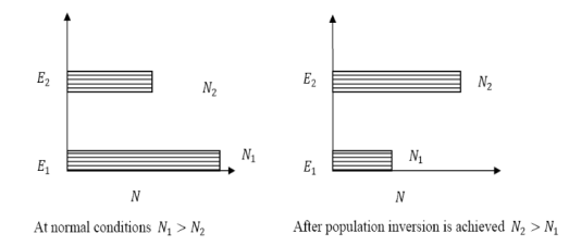
Definition The number of atoms present in the excited state or higher energy state is greater than the number of atoms present in the ground state or lower energy state is called population inversion.
Population inversion as name suggests that this is inverted phenomena. In general lower energy level is more populated that means it have more number of atoms in lower energy level as compared to higher energy level. But by pumping we will obtain a state when the number of atoms present in the higher energy state is greater than the number of atoms present in lower energy state.
Let us consider two level energy system of energies E1 and E2 as shown in figure.
Let N1 and N2 be the populations that means number of atoms per unit volume of energy levels E1 and E2 respectively.
According to Boltzmann’s distribution the population of an energy level E, at temperature T is given by
Ni=N0
Where N0 is the population of the lower level or ground state and k is the Boltzmann’s constant.
From the above relation, the population of energy levels E1 and E2 are
N1=N0 N2=N0 At ordinary conditions N1 >N2 i.e., the population in the ground or lower state is always greater than the population in the excited or higher states. The stage of making, population of higher energy level is greater than the population of lower energy level is called population inversion i.e. N1 < N2
When population inversion method is used to enforce more and more atoms to give up photons. This initiates a chain reaction and releasing massive amount of energy. This results in rapid build-up of energy of emitting one particular wavelength traveling coherently in fixed direction. This process is called amplification by stimulated emission using population inversion. This population inversion situation is essential for a laser action. For any stimulated emission, It is necessary that the upper energy level or meta stable state should have a long life time, i.e., the atoms should pause at the meta stable state for more time than at the lower level.
Pumping mechanisms of population inversion Thus for laser action, pumping mechanism (exciting with external source) maintain a higher population of atoms in the upper energy level relative to that in the lower level. A system in which population inversion is achieved is called as an active system. The method of raising the particles from lower energy state to higher energy state is called pumping. The process of achieving of population inversion is called pumping. This can be done by number of ways. The most commonly used pumping methods are
Optical pumping As the name suggests, in this method, light is used to supply energy to the laser medium. Optical pumping is used in solid laser. Xenon flash tubes are used for optical pumping. Since these materials have very broad band absorption, sufficient amount of energy is absorbed from the emission band of flash lamp and population inversion is created. So xenon flash lamp is used to produce more electrons in the higher energy level of the laser medium. Examples of optically pumped lasers are ruby, Nd: YAG Laser(Neodymium: Yttrium Aluminum Garnet).
Electrical discharge pumping Electrical discharge pumping is used in gas lasers. Since gas lasers have very narrow absorption band pumping then any flash lamp is not possible. Electric discharge refers to flow of electrons or electric current through a gas, liquid or solid. In this method of pumping, electric discharge acts as the pump source or energy source. A high voltage electric discharge (flow of electrons, electric charge, or electric current) is passed through the laser medium or gas. The intense electric field accelerates the electrons to high speeds and they collide with neutral atoms in the gas. As a result, the electrons in the lower energy state gains sufficient energy from external electrons and jumps into the higher energy state Examples of Electrical discharge pumped lasers are He-Ne laser, CO2 laser, argon-ion laser etc. Chemical pumping Chemical reaction may also result in excitation and hence creation of population inversion in few systems. If an atom or a molecule is produced through some chemical reaction and remains in an excited state at the time of production, then it can be used for pumping. The hydrogen fluoride molecule is produced in an excited state when hydrogen and fluorine gas chemically combine. The number of produced excited atoms or molecules is greater than the number of normal state atoms or molecules. Thus, population inversion is achieved. Examples H2 + F2 → 2HF, in this chemical reaction, hydrogen (H2) and fluorine (F2) molecules are chemically combined to produce hydrogen fluoride molecule (2HF) in an excited state. Thermal Pumping: Sometimes we can achieve population inversion by heating the laser medium. In thermal pumping, heat acts as the pump source or energy source. In this method, population inversion is achieved by supplying heat into the laser medium. When heat energy is supplied to the laser medium, the lower energy state electrons gains sufficient energy and jumps into the higher energy level. The process of achieving population inversion in thermal pumping is almost similar to the optical pumping or electric discharge method, except that in this method heat is used as pump source instead of light or electric discharge. Injection current pumping In semiconductors, injection of current through the junction results in creates of population inversion among the minority charge carriers. Examples of such systems are InP and GaAs.
Inelastic Atom-Atom Collisions: Like the electric discharge method, here also a high voltage electric discharge acts as a pump source. However, in this method, a combination of two types of gases, say X and Y are used. The excited state of gas X is represented as X+ whereas gas Y is represented as Y+. Both X and Y gases have the same excited states (X+ and Y+). When high voltage electric discharge passes through a laser medium having two types of gases X and Y, the lower energy state electrons in gas X will move to the excited state X+ similarly the lower energy state electrons in gas Y moves to the excited state Y+. Initially, during electric discharge, the lower energy state electrons in gas X or atom X gets excited to X+ due to continuous collision with electrons. The excited state electrons in gas X+ now collide with the lower energy state electrons in gas Y. As a result, the lower energy state electrons in gas Y gains sufficient energy and jump into the excited state Y+. This method is used in the Helium–Neon (He-Ne) laser. |
- Two-level laser
- Three-level laser
- Four-level laser
Two-level laser
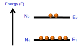
Consider a group of electrons with two energy levels E1 and E2.
E1 is the lower energy state and E2 is the higher energy state.
N1 is the number of electrons in the energy state E1.
N2 is the number of electrons in the energy state E2.
The number of electrons per unit volume in an energy state is the population of that energy state.
|
Population inversion cannot be achieved in a two energy level system. Under normal conditions, the number of electrons (N1) in the lower energy state (E1) is always greater as compared to the number of electrons (N2) in the higher energy state (E2).
N1 > N2
When temperature increases, the population of higher energy state (N2) also increases. However, the population of higher energy state (N2) will never exceeds the population of lower energy state (N1).
At best an equal population of the two states can be achieved which results in no optical gain.
N1 = N2
Two energy level lasers are not possible. We can not get population inversion in a 2 level LASER no matter how much we pump the atoms in the ground state. And since population inversion is a necessity for lasing action, we don't have two level lasers.
Therefore, we need 3 or more energy states to achieve population inversion. The greater is the number of energy states the greater is the optical gain.
There are certain substances in which the electrons once excited; they remain in the higher energy level or excited state for longer period. Such systems are called active systems or active media which are generally mixture of different elements.
When such mixtures are formed, their electronic energy levels are modified and some of them acquire special properties. Such types of materials are used to form 3-level laser or 4-level laser.
Three-level laser
The two energy levels between which lasing occur are: the lower laser energy level (E1), and the upper laser energy level (E2).
To simplify the explanation, we neglect spontaneous emission.
To achieve lasing, energy must be pumped into the system to create population inversion. So, that more atoms will be in energy level E2 than in the ground level (E1).
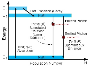
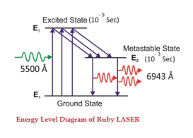
Atoms are pumped from the ground state (E1) to energy level E3. They stay there for an average time of 10-8 [sec], and decay (usually with a non-radiative transition) to the meta-stable energy level E2.
A schematic energy level diagram of a laser with three energy levels is shown in figure,
|
Figure: Energy level diagram in a three level laser
Since the lifetime of the meta-stable energy level (E2) is relatively long (of the order of 10-3 [sec], many atoms remain in this level.
If the pumping is strong enough, then after pumping more than 50% of the atoms will be in energy level E2, a population inversion exists, and lasing can occur.
In a three-level system, the laser transition ends on the ground state. The unpumped gain medium exhibits strong absorption on the laser transition. A population inversion and consequently net laser gain result only when more than half of the ions (or atoms) are pumped into the upper laser level; the threshold pump power is thus fairly high.
The population inversion can be achieved only by pumping into a higher-lying level, followed by a rapid radiative or non-radiative transfer into the upper laser level, because in this way one avoids stimulated emission caused by the pump wave. (For transitions between only two levels, simultaneous pump absorption and signal amplification cannot occur.)
An example of a three-level laser medium is ruby (Cr3+:Al203), as used by Maiman for the first laser.
Four -level laser
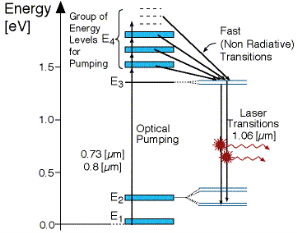
As seen in Figur, there is four energy levels, with energies E1, E2, E3, E4 with populations of N1, N2, N3, N4 respectively. There energies increase for each level so that E1 < E2 < E3 < E4.
|
In this system, optical pumping from the ground state (E1 ) into the pump band (E4) excites the atoms. From this level the atoms decay by a fast, radiationless transition into the level 3 (E3). The lifetime of the laser transition from E3 – E2 is long compared to that of E4 –E3, a population accumulates in this level 3 (lasing level).
Here the atoms relax and start to create laser transitions through spontaneous and stimulated emissions into level 2 (E2). At this level, like level 4 has a fast decay into the ground state. Like before this quickly de-excited atom leads to a negligible population in E2.
This is significant, as the highly populated E3 level will then form a population inversion with the E2 level. Specifically as long as the population of level 3 N3 is greater then 0. Therefore optical amplification and laser operation can take place.
Since only a small number of atoms need to be excited in the upper lasing level E3 to form population inversion, it proves that a 4 level laser is much more efficient and practical then the 3 level laser.
A lower threshold pump power can be achieved with a four-level laser medium, where the lower laser level is well above the ground state and is quickly depopulated e.g. by multi-phonon transitions. Ideally, no appreciable population density in the lower laser level can occur even during laser operation. In that way, reabsorption of the laser radiation is avoided (provided that there is no absorption on other transitions). This means that there is no absorption of the gain medium in the unplumbed state, and the gain usually rises linearly with the absorbed pump power.
The most popular four-level solid-state gain medium is Nd:YAG. All lasers based on neodymium-doped gain media, except those operated on the ground-state transition around 0.9-0.95 pm, are four-level lasers.
Neodymium ions can also be directly pumped into the upper laser level, e.g. with pump light around 880 nm for Nd:YAG. Even though effectively only three levels are involved, the term three-level system would not be used here.
Solid-State Lasers (Ruby Laser)
Ruby laser is a three level solid state laser and was constructed by Maiman in 1960. Ruby laser is one of the few solid-state lasers that produce visible light. It emits deep red light of wavelength 694.3 nm.
Construction
A ruby laser consists of three important elements: laser medium, the pump source and the optical resonator.
Laser Medium
Ruby (Al2O3+Cr2O3) is a crystal of Aluminium oxide, in which 0.05% of Al+3 ions are replaced by the Cr+3 ions. The colour of the rod is pink. The active medium or laser medium in the ruby rod is Cr+3 ions. In ruby laser 4cm length and 5mm diameter rod is generally used. The ruby has good thermal properties.
|
The pump source
The ruby rod is surrounded by xenon flash tube, which provides the pumping light to excite the chromium ions in to upper energy levels. The ruby rod was surrounded by a helical xenon flash lamp.
We know that population inversion is required to achieve laser emission. Population inversion is the process of achieving the greater population of higher energy state than the lower energy state. In order to achieve population inversion, we need to supply energy to the laser medium i.e. to ruby crystal.
Xenon flash tube emits thousands joules of energy in few milliseconds, but only a part of that energy is utilized by the chromium ions while the rest energy heats up the apparatus. A cooling arrangement is provided to keep the experimental set up at normal temperatures.
Optical resonator
Both the ends of the rods are highly polished and made strictly parallel. The ends are silvered in such a way, one becomes partially reflected the laser beam was emitted through that end and the other end fully reflected to reflect all the rays of light striking it.
Working of ruby laser:
Consider a ruby laser medium consisting of three energy levels E1, E2, E3 with N number of electrons.
We assume that the energy levels will be E1 < E2 < E3. The energy level E1 is known as ground state or lower energy state, the energy level E2 is known as metastable state, and the energy level E3 is known as pump state.
Let us assume that initially most of the electrons are in the lower energy state (E1) and only a tiny number of electrons are in the excited states (E2 and E3).
The energy level diagram of chromium ions is shown in figure. The chromium ions get excitation into higher energy levels by absorbing of 5500Å of wavelength radiation. The excited chromium ions stay in the level E3 for short interval of time (10-8 to 10-9 Sec). After their life time most of the chromium ions are de-excited from E3 to E1 and a few chromium ions are de-excited from E3 to E2.
|
The transition between E3 and E2 is non-radioactive transition i.e. the chromium ions gives their energy to the lattice in the form of heat. In the Meta stable state the life time of chromium ions is 10-3 sec. The life time of chromium ions in the Meta stable state is 105 times greater than the life time of chromium ions in higher state.
Due to the continuous working of flash lamp, the chromium ions are excited to higher state E3 and returned to E2 level. After few milliseconds the level E2 is more populated than the level E1 and hence the desired population inversion is achieved. The state of population inversion is not a stable one. The process of spontaneous transition is very high. When the excited chromium ion passes spontaneously from E3 to E2it emits one photon of wave length 6943 Å. The photon reflects back and forth by the silver ends and until it stimulates an excited chromium ion in E2 state and it to emit fresh photon in phase with the earlier photon. The process is repeated again and again until the laser beam intensity is reached to a sufficient value. When the photon beam becomes sufficient intense, it emerges through the partially silvered end of the rod. The wave length 6943 Å is in the red region of the visible spectrum.
Draw backs of ruby laser
The laser requires high pumping power
The efficiency of ruby laser is very small
It is a pulse laser
Application of ruby laser
Ruby lasers are in optical photography
Ruby lasers can be used for measurement of plasma properties such as electron density and temperature.
Ruby lasers are used to remove the melanin of the skin.
Ruby laser can be used for recording of holograms.
The first He-Ne gas laser was fabricated in 1961 by Ali Javan, Bennett and Herriott at Bell Telephone Laboratories. others. Helium-Neon laser is a type of gas laser in which a mixture of helium and neon gas is used as a gain medium. Helium-Neon laser is also known as He-Ne laser. The helium-neon laser was the first continuous wave laser ever constructed. The helium-neon laser operates at a wavelength of 632.8 nanometres (nm), in the red portion of the visible spectrum.
Ruby laser is a pulse laser, even it have high intense output. For continuous laser beam gas lasers are used. Using gas lasers, we can achieve highly coherence, high directionality and high monochromacity beam. The output power of the gas laser is generally in few milliwatts.
Construction
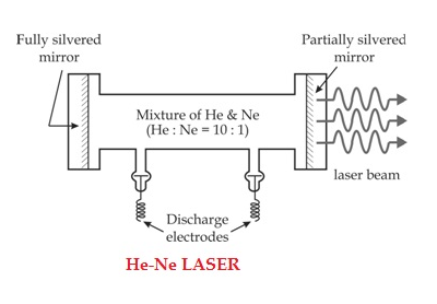
The helium-neon laser consists of three essential components:
- Pump source (high voltage power supply)
- Gain medium (laser glass tube or discharge glass tube)
- Resonating cavity
Pump source
The gain medium of a helium-neon laser is made up of the mixture of helium and neon gas contained in a glass tube at low pressure. In He-Ne gas laser, the He and Ne gases are taken in the ratio 10:1 in the discharge tube.
Gain medium
In He-Ne laser 80cm length and 1cm diameter discharge is generally used. The out power of these lasers depends on the length of the discharge tube and pressure of the gas mixture. Therefore, in order to achieve population inversion, we need to pump electrons from lower energy state of the helium. In He-Ne laser, neon atoms are the active centres and have energy levels suitable for laser transitions while helium atoms help in exciting neon atoms.
|
Resonating cavity
Two reflecting mirrors are fixed on either ends of the discharge tube, in that, one is partially reflecting and the other is fully reflecting. The fully silvered mirror will completely reflect the light whereas the partially silvered mirror will reflect most part of the light but allows some part of the light to produce the laser beam.
Working
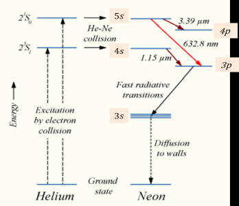
When the electric discharge is passing through the gas mixture, the electrons accelerated towards the positive electrode. During their passage, they collide with He atoms and excite them into higher levels. 23s1 and 21s0 form ground state of He atom. In higher levels 23s1 and 21s0, the life time of He atoms is more. So there is a maximum possibility of energy transfer between He and Ne atoms through atomic collisions. When He atoms present in the levels 23s1 and 21s0 collide with Ne atoms present ground state, the Ne atoms gets excitation into higher levels 4s and 5s.
Due to the continuous excitation of Ne atoms, we can achieve the population inversion between the higher levels 4s and 5s and lower levels 3p and 4p. The various transitions 5s to 4p, 4s to 3p and 5s to 3p leads to the emission of wavelengths 3.93μm, 1.51μm and 6328 Å or 632.8μm.
|
The first two corresponding to the infrared region while the last wavelength is corresponding to the visible region. The Ne atoms present in the 4s level are de-excited into 3s level, by spontaneously emitting a photon of around wavelength 6000 Å. When a narrow discharge tube is used, the Ne atoms present in the level 3s collide with the walls of the tube and get de-excited to ground state energy level.
Advantages of helium-neon laser
- Helium-neon laser emits laser light in the visible portion of the spectrum.
- High stability
- Low cost
- Operates without damage at higher temperatures
Disadvantages of helium-neon laser
- Low efficiency
- Low gain
- Helium-neon lasers are limited to low power tasks
Applications of helium-neon lasers
- Helium-neon lasers are used in industries.
- Helium-neon lasers are used in scientific instruments.
- Helium-neon lasers are used in the college laboratories.
Applications of Lasers in Science, Engineering And Medicine.
Applications of lasers because of unique property of laser beam such as coherence, monochromacity, directionality, and high intensity, they are widely used in various fields like
1. Communication
2. Computers
3. Chemistry
4. Photography
5. Industry
6. Medicine
7. Military
8. Scientific Research
1. Communication
In case of optical communication semiconductors laser diodes are used as optical sources and its band width is (1014Hz) is very high compared to the radio and microwave communications. More channels can be sent simultaneously Signal cannot be tapped as the band width is large, more data can be sent. A laser is highly directional and less divergence, hence it has greater potential use in space crafts and submarine. It is used in optical fiber communications to send information over large distances with low loss. Laser light is used in underwater communication networks. Lasers are used in space communication, radars and satellites.
2. Computers
In LAN (local area network), data can be transferred from memory storage of one computer to other computer using laser for short time. Lasers are used in CD-ROMS during recording and reading the data. Lasers are used in computer printers.
3. Chemistry
Lasers are used in molecular structure identification Lasers are also used to accelerate some chemical reactions. Using lasers, new chemical compounds can be created by breaking bonds between atoms are molecules.
4. Photography
Lasers can be used to get 3-D lens less photography. Lasers are also used in the construction of holograms.
5. Industry
Lasers can be used to blast holes in diamonds and hard steel. Lasers are also used as a source of intense heat Carbon dioxide laser is used for cutting drilling of metals and non-metals, such as ceramics plastics glass etc. High power lasers are used to weld or melt any material. Lasers are also used to cut teeth in saws and test the quality of fabric. It is used to cut glass and quartz, used in electronic industries for trimming the components of Integrated Circuits (ICs).Lasers are used for heat treatment in the automotive industry. Laser light is used to collect the information about the prefixed prices of various products in shops and business establishments from the bar code printed on the product. Ultraviolet lasers are used in the semiconductor industries for photolithography. Photolithography is the method used for manufacturing printed circuit board (PCB) and microprocessor by using ultraviolet light. It is also used to drill aerosol nozzles and control orifices within the required precision.
6. Medicine
Pulsed neodymium laser is employed in the treatment of liver cancer. Argon and carbon dioxide lasers are used in the treat men of liver and lungs. Lasers used in the treatment of Glaucoma.
Lasers used in endoscopy to scan the inner parts of the stomach. Lasers used in the elimination of moles and tumors which are developing in the skin tissue and hair removal. It is also used for bloodless surgery.
Lasers are used to destroy kidney stones, in cancer diagnosis and therapy also used for eye lens curvature corrections. Lasers are used to study the internal structure of microorganisms and cells. It is used to create plasma. Lasers are used to remove the caries or decayed portion of the teeth.
7. Military
Lasers can be used as a war weapon. High energy lasers are used to destroy the enemy air-crofts and missiles. Lasers can be used in the detection and ranging likes RADAR. Laser range finders are used to determine the distance to an object. The ring laser gyroscope is used for sensing and measuring very small angle of rotation of the moving objects.
Lasers can be used as a secretive illuminator for reconnaissance during night with high precision.
8. Scientific research
Lasers are used in the field of 3D-photography Lasers used in Recording and reconstruction of hologram. Lasers are employed to create plasma. Lasers are used in Raman spectroscopy to identify the structure of the molecule and to count the number of atoms in a substance. Lasers are used in the Michelson- Morley experiment. A laser beam is used to confirm Doppler shifts in frequency for moving objects. A laser helps in studying the Brownian motion of particles. With the help of a helium-neon laser, it was proved that the velocity of light is same in all directions. Lasers are used to measure the pollutant gases and other contaminants of the atmosphere. Lasers help in determining the rate of rotation of the earth accurately. Lasers are used for detecting earthquakes and underwater nuclear blasts. A gallium arsenide diode laser can be used to setup an invisible fence to protect an area.
Holography
Another important application of laser beam is the production of true three-dimensional pictures in space without the use of lens. The record of' this three-dimensional image of the object on a film is called a hologram.
The phenomena called interference produced due to interaction of two beam monochromatic light waves under certain conditions. The interference pattern is produced by mixing two beams of the laser light. Laser light is split into two beams. One beam called the reference beam is directed toward photographic plate. The other beam is direct towards the object to be recorded, so that suitably reflected from the object. The reference beam and the reflected beam are made to with each other to form an interference patter the photographic plate.
To get a high quality hologram, radiation of in high coherence is required. Generally, the helium-neon gas laser which gives highly coherent beam and Its continuous output beam is used for this purpose. The holograms are recorded on special photographic plates with good resolution. The plate is developed and fixed in the usual way.
Reference Books
1. Concepts of Modern Physics - AurthurBeiser (Mc-Graw Hill)
2. Introduction to Special Theory of Relativity- Robert Resnick (Wiley)
3. Optics - Brijlal& Subramanian (S. Chand )
4. Engineering Physics: Theory and Practical- Katiyar and Pandey (Wiley India)
5. Applied Physics for Engineers- Neeraj Mehta (PHI Learning, New)
6. Engineering Physics-Malik HK and Singh AK (McGrawHill)
