Unit-5
Fundamentals of Communication Engineering
The telegraph was invented in 1844. [ Morse Patent ]
The telephone was invented in 1876. [ Bell Patent ]
In 1887 radio was invented [ Hertz invent ]
In 1895 Marconi demonstrates wireless telegraphy.
1923 : Television is invented.
1948 : Transistor is invented.
1954 :Color television broadcasting begins
1969 : The internet is invented.
1983 : First cellular telephone system becomes operational.
1989 : GPS is used for commercial and personal applications.
1989 : www is invented.
1998 : The first commercial use of digital / high definition television takes place.
Simplex is one way communication.
Duplex is two-way communication.
Telegraph used Morse code whereas radio telegraphy used an international code of dots and dashes.
The most commonly used digital code in communications is the American Standard code for information interchange [ ASCII ].
Putting the original voice, video or digital signals directly into the medium is referred to as baseband transmission.
Eg : telephone and intercom communications systems. In some computer network ie digital signals are applied directly to coaxial cables for transmission to another computer.
To transmit baseband signals by radio, modulation techniques must be used. Techniques using modulation are referred to as broadband.
Modulation is the process of having a baseband voice, video or digital signal modify another higher frequency signal called the carrier.
In AM, the baseband signal varies the amplitude of the higher frequency carrier signal.

In FM the baseband signal varies the frequency of the carrier.
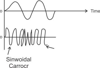
Shifting the phase of the carrier in accordance with the i/p modulating signal produces phase modulation (PM). Phase modulation produces FM so a PM signal looks like the FM.
Electromagnetic signals are also referred to as radio frequency ( Rf ) waves.
The electromagnetic spectrum used in electronic communication
The ionosphere refracts radio waves making long distance communication possible for some frequencies at certain times.
The visible range is approximately 8000 Ao ( red ) to 4000 Ao ( violet ).
Light wavelengths are usually expressed in terms of angstroms ( Ao ).
An angstrom is one ten thousandth of a micron.
Light is widely used for various kinds of communications. The great advantage of light wave signals is that their very high frequency gives them the ability to handle a tremendous amount of information. That is the bandwidth of the baseband signals may be very wide.
Audio signals are not transmitted by electromagnetic waves because
1>. Antennas would be too long.
2>. Simultaneous transmission would interfere.
HF signals are also called share waves.
Frequency above 1 GHz are called microwave.
Any broadcasting audio signals upto 5 KHz may be transmitted.
Government also established the Federal communication’s Commission [ FCC ] which is a regulatory body whose sole purpose is allocating spectrum space, issuing licences, setting standards & policing the airwaves.
The FCC controls all telephone & radio communications in this country & in general regulates all electromagnetic emissions.
The national telecommunications and information administration [ NTIA ] performs a similar function for government & military services.

Fig. 1 Block diagram of elements of communication (ref 3)
Information Source
It produces a message that is analog in nature, i.e., the output of the information source is a continuous signal.
Analog carrier source
Sine wave is used as a carrier signal which will help in analog modulation.
Analog modulation
The carrier signal is superimposed with the message signal and then the modulated signal is obtained which is also analog in nature.
Communication channel
The analog modulated signal is transmitted via the communication channel towards the receiver end after addition of the requisite power levels.
Analog demodulation
At the receiver end, the incoming modulated signal is passed through an analog demodulation process which extracts the analog message signal. The analog message is then passed onto the final destination.
Destination
The nature of signal starting from the information source till the final destination is analog.
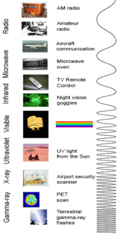
Radio: Your radio captures radio waves emitted by radio stations, bringing your favourite tunes. Radio waves are also emitted by stars and gases in space.
Microwave: Microwave radiation will cook your popcorn in just a few minutes, but is also used by astronomers to learn about the structure of nearby galaxies.
Infrared: Night vision goggles pick up the infrared light emitted by our skin and objects with heat. In space, infrared light helps us map the dust between stars.
Visible: Our eyes detect visible light. Fireflies, light bulbs, and stars all emit visible light.
Ultraviolet: Ultraviolet radiation is emitted by the Sun and are the reason skin tans and burns. "Hot" objects in space emit UV radiation as well.
X-ray: A dentist uses X-rays to image your teeth, and airport security uses them to see through your bag. Hot gases in the Universe also emit X-rays.
Gamma ray: Doctors use gamma-ray imaging to see inside your body. The biggest gamma-ray generator of all is the Universe.
1>. Antenna height reduces
2>. Avoids mixing of signal
3>. Increases the range of communication [ In Kilometers]
4>. Multiplexing of signals is possible
5>. Improves quality of reception of signal.
1>. Antenna height Reduces: - Antenna theory specifies that the height of the antenna required for radiation of radio waves is a function of wavelength of the frequency fed at the i/p of the antenna. Antenna height must be multiple of ( d/4 ),
Where ‘ d ‘ is the wavelength.
d = speed of light / frequency of signal
d = c / f = 3 x 10⁸ / f
eg : Consider the voice as analog baseband signal with f = 4 KHz
d = 3 x 10⁸ / 4 x 10³
d = 75 x 103 m
d = 75 km
Height of antenna required is d / 4
= 75 km / 4 = 18.75 km
Q. Practically you cannot build the antenna of 18.7 km height. Consider this voice signal of 4 kHz frequency is used to modulate the carrier signal of 2 MHz frequency.
F = 2 MHz
D = c / f = 3 x 10⁸ / 2 x 106 = 150 m
Minimum height of antenna required = d / 4 = 150 / 4 = 37.5 m
Therefore, antenna height required for radio communication reduces from 75 km to 37.5 meters due to modulation.
2>. Increase range of communication: - The frequency of baseband signal is low. At low frequency the signal radiation from antenna is poor or weak. Due to this reason the signal gets attenuated and can’t travel long distance when it is transmitted.
Attenuation of the transmitted signal reduces when the frequency is increased.
Thus modulation increases the frequency of the signal to be radiated. Thus, increase in frequency increases the range of communication.
Key Takeaways:
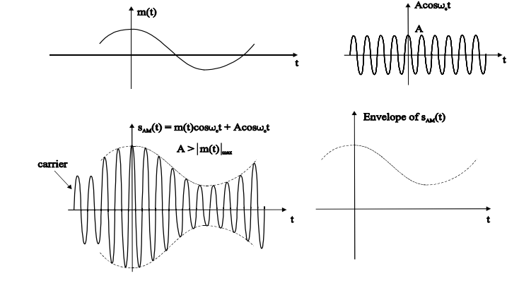
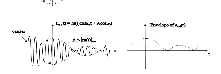
The amplitude of the carrier signal varies in accordance with the instantaneous amplitude of the modulating signal. That is the amplitude of the carrier signal containing no information varies as per the amplitude of the signal containing information, at each instant.
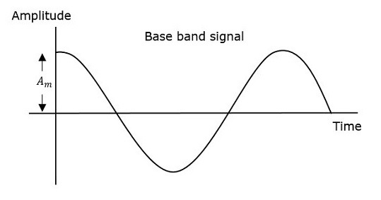
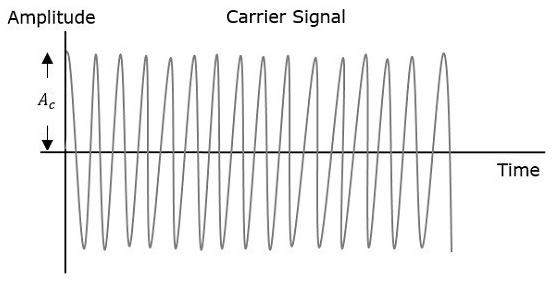
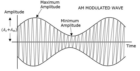
Consider the following diagram
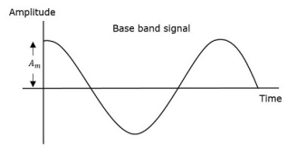

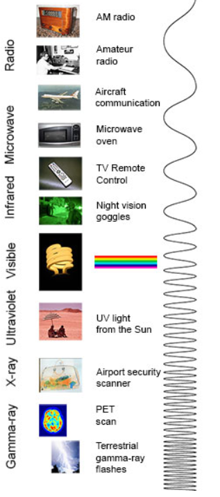
Fig.: AM
The first figure shows the modulating wave, which is the message signal. The next one is the carrier wave, which is a high frequency signal and contains no information. While, the last one is the resultant modulated wave.
It can be observed that the positive and negative peaks of the carrier wave are interconnected with an imaginary line. This line helps recreating the exact shape of the modulating signal. This imaginary line on the carrier wave is called as Envelope. It is the same as that of the message signal.
Therefore, we can say that Amplitude Modulation is the process of changing the amplitude of a relatively high frequency carrier signal in accordance with the amplitude of the modulating signal (Information). The carrier amplitude varies linearly by the modulating signal which usually consists of a range of audio frequencies. The frequency of the carrier is not affected.
The various forms of Amplitude Modulation are:
DSBFC (Double Side Band Full Wave Carrier)
Time-Domain Representation
Let the modulating signal be,
m(t)=Am cos(2πfmt ) --------------(1)
and the carrier signal be,
c(t)=Ac cos(2πfct)c(t) ---------------(2)
where, Am and Ac are the amplitude of the modulating signal and the carrier signal respectively.
fm and fc are the frequency of the modulating signal and the carrier signal respectively.
Then, the equation of Amplitude Modulated wave will be
s(t)=[Ac+ Am cos(2πfmt)] cos(2πfct) -------------------------- (3)
s(t) = [ Ac cos(2πfct) + Ac Am cos(2πfmt) . cos(2πfct) ] ---------(4)
s(t) = Ac[1 + Am/Ac cos(2πfmt)] cos(2πfct) ----------- (5)
Here the modulation index µ = Am/Ac.
s(t) = Ac[1 + µ cos(2πfmt)] cos(2πfct) -------------- (6)
Modulation index
Let Amax and Amin be the maximum and minimum amplitudes of the modulated wave.
We will get the maximum amplitude of the modulated wave, when cos(2πfmt)
is 1.
That is Amax=Ac + Am
We will get the minimum amplitude of the modulated wave, when cos(2πfmt)
is -1.
That is Amin = Ac - Am
Amax + Amin = Ac + Am + Ac –Am = 2Ac
Ac = Amax + Amin/2
Similarly Amax – Amin = Ac + Am – Ac +Am = 2Am
Am = Amax – Amin /2
Therefore
µ = Amax + Amin
Amax - Amin
Bandwidth:
Bandwidth is the difference between the highest and lowest frequencies of the signal.
BW = fmax – fmin
s(t) = Ac[1+ μcos(2πfmt)] cos(2πfct)
s(t) = Ac cos(2πfct) + Ac μcos(2πfmt) cos(2πfct)
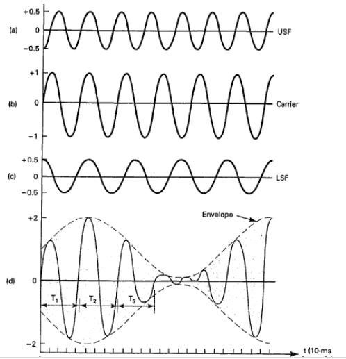
s(t) = Ac cos(2πfct) + Ac μ/2 cos 2π (fc + fm)t + Ac μ/2 cos 2π (fc - fm)t
Hence, the amplitude modulated wave has three frequencies.
Here, fmax=fc+fm and fmin=fc−fm
BW=fc+fm−(fc−fm)
BW=fc+fm−(fc−fm)
BW=2fm
Power Calculation of AM
Consider the following equation of amplitude modulated wave.
s(t)=Ac cos(2πfct)+Acμ 2 cos[2π(fc+fm)t]+ Acμ 2cos[2π(fc−fm)t] -------(1)
Power of AM wave is equal to the sum of powers of carrier, upper sideband, and lower sideband frequency components.
Pt=Pc+ PUSB+ PLSB
We know that the standard formula for power is
P = vrms 2 / R = (vm /  ) 2 /2
Where,
Vrms is the rms value of cos signal.
vm is the peak value of cos signal.
The powers of the carrier, the upper and lower sideband is given by
Carrier power
Pc=(Ac/√2)2/R=Ac2/2R
Upper sideband power
PUSB=(Acμ/2√2)2/R= Ac2 μ2/ 8R
Similarly, for lower sideband power same as that of the upper side band power.
PLSB=(Acμ/2√2)2 /R
PLSB=Ac2μ2/R
Now, let us add these three powers in order to get the power of AM wave.
Pt=Ac2 /2R+Ac2μ2 /8R+Ac2μ2/8R
Pt= Ac2 /2R[ 1+μ2 /4+μ2 /4]
Pt=Pc ( 1+ μ 2/2 )
Problems
A modulating signal m(t)=10cos(2π×103t)m(t) is amplitude modulated with a carrier signal c(t)=50cos(2π×105t). Find the modulation index, the carrier power, and the power required for transmitting AM wave.
Solution
Given, the equation of modulating signal as
m(t)=10cos(2π×103t)m(t)
We know the standard equation of modulating signal as
m(t)=Amcos(2πfmt)m(t)
By comparing the above two equations, we will get
Am=10volts
and Frequency of modulating signal as
fm=103Hz=1KHz
Given, the equation of carrier signal is
c(t)=50cos(2π×105t))
The standard equation of carrier signal is
c(t)=Accos(2πfct)c(t)
By comparing these two equations, we will get
Amplitude of carrier signal as Ac=50voltsAc
and Frequency of carrier signal as fc=105Hz=100KHz
We know the formula for modulation index as
μ=Am/Ac
μ=10/50=0.2
Therefore, the value of modulation index is 0.2 and percentage of modulation is 20%.
The formula for Carrier power, Pc
Pc=Ac2 /2R
Assume R=1ΩR=1Ω and substitute Ac value in the above formula.
Pc=(50)2/2(1)=1250W
Therefore, the Carrier power, Pc is 1250 watts.
We know the formula for power required for transmitting AM wave is
Pt=Pc(1+μ2/2)
Pt=1250(1+(0.2)22)=1275W
Therefore, the power required for transmitting AM wave is 1275 watts
DSBSC (Double Side Band Suppressed Carrier)
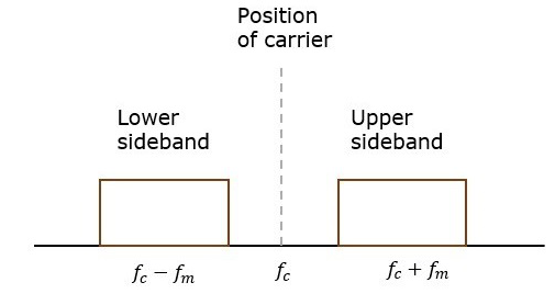
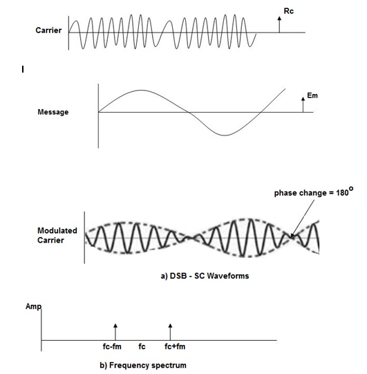
In DSBC modulation, the modulated wave consists of only the upper and lower side bands. Transmitted power is saved through the suppression of the carrier wave, but the channel bandwidth requirement is the same.
DSBSC modulators make use of the multiplying action in which the modulating signal multiplies the carrier wave. In this system, the carrier component is eliminated and both upper and lower side bands are transmitted. As the carrier component is suppressed, the power required for transmission is less than that of AM.
Carrier is suppressed and base band is allowed for transmission.
If m(t) = Am cos(2πfmt) is the modulating signal and c(t) = Ac cos(2πfct) is the carrier signal then DSBSC wave s(t) is given by
s(t) = c(t) m(t) ------------------- (1)
s(t) =Am cos(2πfmt) Ac cos(2πfct) -------- (2)
s(t) = Am Ac cos(2πfmt) cos(2πfct) ------- (3)
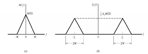
The figure shows the waveform and the frequency spectrum.
The envelope of a DSBSC modulated signal is therefore different from the message signal and the Fourier transform of s(t) is given by
S(f) = Ac/2[ M(f-fc) + M(f + fc)]
When base band signal m(t) is limited to interval –W<fc<W we find the spectrum S(f) of the DSBSC wave s(t) as shown in the figure. We see that there is a change in the scaling factor, the modulation process translates the spectrum of the base band signal by fc. The transmission bandwidth is same as AM.
Bandwidth of DSBSC Wave
We know the formula for bandwidth (BW) is
BW=fmax−fmin
Consider the equation of DSBSC modulated wave.
s(t)=Am Ac cos(2πfmt)cos(2πfct)s(t)
s(t)=AmAc2cos[2π(fc+fm)t]+AmAc2cos[2π(fc−fm)t]
The DSBSC modulated wave has only two frequencies. So, the maximum and minimum frequencies are fc+ fm and fc− fm respectively.
i.e. fmax=fc+fm and fmin=fc−fm
BW=fc+fm−(fc−fm)
BW = 2fm
Thus, the bandwidth of DSBSC wave is same as that of AM wave and it is equal to twice the frequency of the modulating signal.
Power of DSBSC Wave
Consider the following equation of DSBSC modulated wave.
s(t)=AmAc2cos[2π(fc+fm)t]+AmAc2cos[2π(fc−fm)t]
Power of DSBSC wave is equal to the sum of powers of upper sideband and lower sideband frequency components.
Pt=PUSB+PLSB
We know the standard formula for power of cos signal is
P=vrms2 /R=(vm√2)2 /R
First, let us find the powers of upper sideband and lower sideband one by one.
Upper sideband power
PUSB=(AmAc/2√2)2/R=Am2Ac2 / 8R
Similarly, we will get the lower sideband power same as that of upper sideband power.
PLSB=Am2Ac2/8R
Now, let us add these two sideband powers in order to get the power of DSBSC wave.
Pt=Am2Ac2 /8R+Am2Ac2/8R
Pt=Am2Ac2 /4R
Therefore, the power required for transmitting DSBSC wave is equal to the power of both the sidebands.
Generation of DSBSC Waves:
Balanced Modulator (Product Modulator)
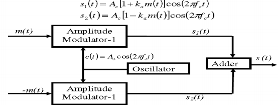
A balanced modulator consists of two standard amplitude modulators arranged in a balanced configuration so as to suppress the carrier wave as shown in the following block diagram. It is assumed that the AM modulators are identical, except for the sign reversal of the modulating wave applied to the input of one of them. Thus, the output of the two modulators may be expressed as,
Balanced Modulator
Subtracting s2(t) from s1(t) we get
s(t) = s1(t) – s2(t)
s(t) = 2 ka m(t) cos(2πfct)
Hence, except for the scaling factor 2ka, the balanced modulator output is equal to the product of the modulating wave and the carrier.
Operation
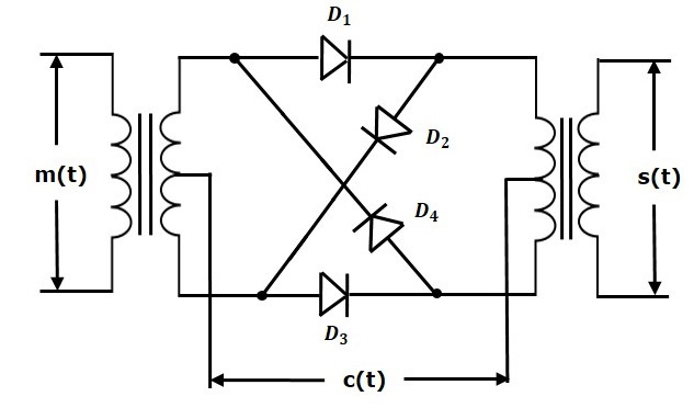
From the above analysis, we can say that the four diodes D1, D2, D3 and D4 are controlled by the carrier signal.
If the carrier is a square wave, then the Fourier series representation of c(t) is given by
c(t) = 4 / π  n-1 / 2n -1 cos[2πfct(2n−1)]
We will get DSBSC wave s(t) which is just the product of the carrier signal c(t)) and the message signal m(t) i.e.,
s(t) = 4 / π  n-1 / 2n -1 cos[2πfct(2n−1)] m(t)
the ring modulator.
DSBSC modulators are known as product modulators as they produce the output, which is the product of two input signals.
Balanced Modulator using Non-linear resistance
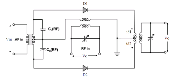
As indicated in the Figure, the input voltage at diode D1 is vc+vm and input voltage at diode D2 is vc−vm.
The primary current of the output transformer is i1=id1−id2.
where,
id1=a+ b(vc+vm)+ c(vc+vm)2
id2=a+ b(vc−vm)+c(vc−vm)2
Thus, we get,
i1= id1−id2=2bvm+4cvmvc
The modulating and carrier voltage are represented as,
vm=Vm sinωmt and vc=Vc sinωct
Substituting for vm and vc and simplifying, we get,
i1=2bVmsinωmt+4cmVc/2cos(ωc−ωm)t−4cmVc/2cos(ωc+ωm)t
The output voltage v0 is proportional to primary current i1 and assume constant of proportionality as α, which can be expressed as,
v0=αi1=2αbVmsinωmt+4αcmVc/2cos(ωc−ωm)t−4αcmVc/2cos(ωc+ωm)t
Let P=2αbVmP and Q=2αcmVc2.
Thus we have,
v0=Psinωmt+2Qcos(ωc−ωm)t−2Qcos(ωc+ωm)t
The above equation shows that carrier has been cancelled out , leaving only two
sidebands and the modulating frequencies from the output is eliminated by the tuning of the output transformer, which results in the below equation of the generated DSBSC wave.
v0=2Qcos(ωc−ωm)t−2Qcos(ωc+ωm)t
Switching Modulator
.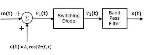
Switching modulator is similar to the square law modulator. The only difference is that in the square law modulator, the diode is operated in a non-linear mode, whereas, in the switching modulator, the diode has to operate as an ideal switch.
Let the modulating and carrier signals be denoted as m(t) and c(t)=Accos(2πfct). These two signals are applied as inputs to the summer (adder) block. Summer block produces an output, which is the addition of modulating and carrier signals. Mathematically, we can write it as
V1(t)=m(t)+c(t)=m(t)+Accos(2πfct)
This signal V1(t) is applied as an input of diode.
Assume, the magnitude of the modulating signal is very small when compared to the amplitude of carrier signal Ac. So, the diode’s ON and OFF action is controlled by carrier signal c(t). This means, the diode will be forward biased when c(t)>0 and it will be reverse biased when c(t)<0.
Therefore, the output of the diode is
V2(t)={V1(t)0 if c(t)>0
0 c(t) <0
We can approximate this as
V2(t)=V1(t)x(t)
Where, x(t) is a periodic pulse train with time period T=1fc

The Fourier series representation of this periodic pulse train is
x(t)=1/ 2+2π  n -1 / 2n-1 cos( 2π(2n-1) fc(t))---------------------(1)
= ½ + 2/π cos(2πfct) -2 / 3 π cos(6πfct)+ ………… ----------------(2)
Substituting V1(t) and x(t) we get
V2(t) = [m(t) + Ac cos(2πfct) ] [½ + 2/π cos(2πfct) -2 / 3 π cos(6πfct)+ …………]---------------------------------------(3)
V2(t) = Ac/2 (1+ 4/πAc)m(t) cos(2πfct) + m(t)/2 + 2Ac/π cos (2πfct)- 2m(t)/3π cos(6 πfct)- 2A/3π cos(2πfct) cos(6πfct) + ………………………….
The 1st term of the above equation represents the desired AM wave and the remaining terms are unwanted terms. Thus, with the help of band pass filter, we can pass only AM wave and eliminate the remaining terms.
Therefore, the output of switching modulator is
s(t)=Ac2(1+(4π/Ac)m(t))cos(2πfct)
We know the standard equation of AM wave is
s(t)=Ac[1+kam(t)]cos(2πfct)s(t)
Where, ka is the amplitude sensitivity.
By comparing the output of the switching modulator with the standard equation of AM wave, we will get the scaling factor as 0.5 and amplitude sensitivity ka as 4π/Ac.
The process of suppressing one of the sidebands along with the carrier and transmitting a single sideband is called as Single Sideband Suppressed Carrier system or simply SSBSC. It is plotted as shown in the following figure.
Carrier and sideband are suppressed and single sideband is allowed for transmission.
Let us consider the
Modulating signal
m(t)=Am cos(2πfmt)
Carrier signal
c(t)=Ac cos(2πfct)
Mathematically, we can represent the equation of SSB-SC wave as
s(t)=AmAc2cos[2π(fc+fm)t] for the upper sideband
Or
s(t)= AmAc2cos[2π(fc−fm)t] for the lower sideband
Bandwidth of SSB-SC Wave
We know that the DSB-SC modulated wave contains two sidebands and its bandwidth is 2fm. Since the SSB-SC modulated wave contains only one sideband, its bandwidth is half of the bandwidth of DSBSC modulated wave.
i.e., Bandwidth of SSBSC modulated wave =2fm/2=fm
Therefore, the bandwidth of SSB-SC modulated wave is fm and it is equal to the frequency of the modulating signal.
Power Calculations of SSB-SC Wave
Consider the following equation of SSBSC modulated wave.
s(t)=AmAc/2 cos[2π(fc+fm)t] for the upper sideband
Or
s(t)=AmAc/2 cos[2π(fc−fm)t] for the lower sideband
Power of SSB-SC wave is equal to the power of any one sideband frequency components.
Pt=PUSB=PLSB
We know power
P=vrms2 / R
=(vm/√2)2 / R
In this case, the power of the upper sideband is
PUSB=(AmAc/2√2)2 / R = Am2Ac2 /8R.
Similarly, for lower sideband power.
PLSB=Am2Ac2 / 8R
Therefore, the power of SSB-SC wave is
Pt=Am2Ac2 / 8R
Advantages
Disadvantages
Applications
Generation of SSB-SC
We can generate SSBSC wave using the following two methods.
Frequency Discrimination Method
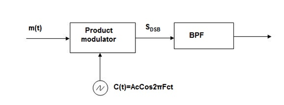
In this method the DSB signal is passed through band pass filter to generate SSB signal.
The center frequency of the band pass signal decides whether USB or LSB signal is generated.
Suppose we want to transmit USB then using band pass filter with center frequency fc + w/2 we obtain the desired result as shown in the figure.
Phase Discriminated Method:
Consider the following block diagram of SSB-SC modulator using phase discrimination method.
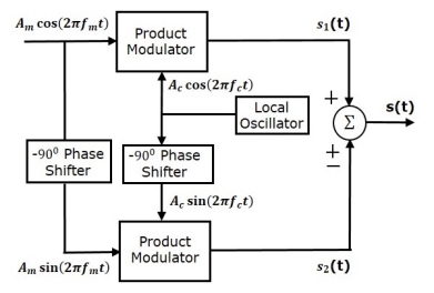
The modulating signal
m(t) = Am cos(2πfmt) -----------------(1)
the carrier signal
c(t) = Ac cos(2πfct) -----------------------(2)
which are directly applied as inputs to the upper product modulator. So, the upper product
modulator produces an output, which is the product of these two inputs.
The output of upper product modulator is
s1(t)=AmAc cos(2πfmt)cos(2πfct) --------------------(3)
s1(t)=AmAc/2{cos[2π(fc+fm)t]+cos[2π(fc−fm)t]} -----------(4)
The modulating signal Am cos(2πfmt) and the carrier signal Ac cos(2πfct) are phase shifted by −900 before applying as inputs to the lower product modulator. So, the lower product modulator produces an output, which is the product of these two inputs.
The output of lower product modulator is
s2(t)=AmAc cos(2πfmt−900)cos(2πfct−900) ---------------(5)
s2(t)=AmAc sin(2πfmt) sin(2πfct) -------------------(6)
s2(t)=AmAc/2{cos[2π(fc−fm)t]−cos[2π(fc+fm)t]} ----------(7)
Add s1(t) and s2(t) in order to get the SSB-SC modulated wave s(t) having a lower sideband.
s(t)=AmAc/2{cos[2π(fc+fm)t]+cos[2π(fc−fm)t]}+AmAc/2{cos[2π(fc−fm)t]−cos[2π(fc+fm)t]} ----------------------------------(8)
s(t)=AmAc cos[2π(fc−fm)t] ------------------------(9)
Subtract s2(t) from s1(t) in order to get the SSBSC modulated wave s(t) having a upper sideband.
s(t)=AmAc/2{cos[2π(fc+fm)t]+cos[2π(fc−fm)t]}−AmAc/2{cos[2π(fc−fm)t]−cos[2π(fc+fm)t]} ---------------------------------------------------------(10)
s(t)=AmAc cos[2π(fc+fm)t] --------------------------(11)
Hence, by properly choosing the polarities of inputs at summer block, we will get SSB-SC wave having a upper sideband or a lower sideband.
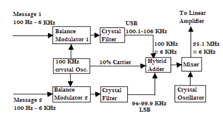
2. ISB(Independent Sideband Transmission)
3. VSB (Vestigial Side Band Suppressed Carrier)
We can get one sideband frequency component completely by using an ideal band pass filter. However, practically we may not get the entire sideband frequency component. Because of this, some information gets lost.
To avoid this loss, a technique is chosen, which is a compromise between DSBSC and SSBSC. This technique is known as Vestigial Side Band Suppressed Carrier (VSBSC) technique. The word “vestige” means “a part” from which, the name is derived.
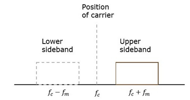
VSBSC Modulation is the process, where a part of the signal called as vestige is modulated along with one sideband. The frequency spectrum of VSBSC wave is shown in the figure.
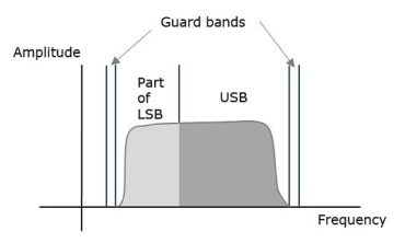
Along with the upper sideband, a part of the lower sideband is also transmitted in this technique. Similarly, we can transmit the lower sideband along with a part of the upper sideband. A guard band of very small width is laid on either side of VSB in order to avoid the interferences. VSB modulation is mostly used in television transmissions.
Bandwidth of VSBSC Modulation
We know that the bandwidth of SSBSC modulated wave is fm. Since the VSBSC modulated wave contains the frequency components of one side band along with the vestige of other sideband, the bandwidth of it will be the sum of the bandwidth of SSBSC modulated wave and vestige frequency fv.
Therefore,
Bandwidth of VSBSC Modulated Wave = fm+fv
Advantages
Disadvantages
Applications
The most prominent and standard application of VSBSC is for the transmission of television signals. This is the most convenient and efficient technique when bandwidth usage is considered.
Generation of VSBSC
Generation of VSBSC wave is similar to the generation of SSBSC wave. The VSBSC modulator is shown in the following figure.
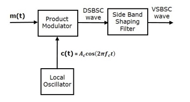
In this method, first we will generate DSBSC wave with the help of the product modulator. Then, apply this DSBSC wave as an input of sideband shaping filter. This filter produces an output, which is VSBSC wave.
The modulating signal m(t)) and carrier signal Ac cos(2πfct) are applied as inputs to the product modulator. Hence, the product modulator produces an output, which is the product of these two inputs.
Therefore, the output of the product modulator is
p(t)=Ac cos(2πfct)m(t)------------------------(1)
Apply Fourier transform on both sides
P(f)=Ac/2[M(f−fc)+M(f+fc)]-------------------(2)
The above equation represents the equation of DSBSC frequency spectrum.
Let the transfer function of the sideband shaping filter be H(f). This filter has the input p(t) and the output is VSBSC modulated wave s(t). The Fourier transforms of p(t) and s(t) are P(f) and S(f) respectively.
Mathematically, we can write
S(f)= =P(f)H(f)------------------(3)
Substitute P(f) value in the above equation.
S(f)=Ac/2[M(f−fc)+M(f+fc)]H(f)-----------------------------(4)
The above equation represents the equation of VSBSC frequency spectrum.
Demodulation of VSBSC
Demodulation of VSBSC wave is similar to the demodulation of SSBSC wave. Here, the same carrier signal used for generating VSBSC wave is used to detect the message signal. Hence, this process of detection is called as coherent or synchronous detection. The VSBSC demodulator is shown in the following figure.
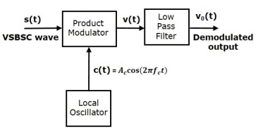
In this process, the message signal can be extracted from VSBSC wave by multiplying it with a carrier, which is having the same frequency and the phase of the carrier used in VSBSC modulation. The resulting signal is then passed through a Low Pass Filter. The output of this filter is the desired message signal.
Let the VSBSC wave be s(t) and the carrier signal is Ac cos(2πfct)
From the figure, we can write the output of the product modulator as
v(t)=Ac cos(2πfct)s(t)----------------------(1)
Apply Fourier transform on both sides
V(f)=Ac/2[S(f−fc)+S(f+fc)]--------------------------(2)
We know that
S(f)=Ac/2[M(f−fc)+M(f+fc)]H(f)-------------------------(3)
From the above equation, let us find S(f−fc )and S(f+fc).
S(f−fc)=Ac/2[M(f−fc−fc)+M(f−fc+fc)]H(f−fc)-----------------------------(4)
S(f−fc)=Ac/2[M(f−2fc)+M(f)]H(f−fc)------------------------------------(5)
S(f+fc)=Ac/2[M(f+fc−fc)+M(f+fc+fc)]H(f+fc)--------------- (6)
S(f+fc)=Ac/2[M(f)+M(f+2fc)]H(f+fc)---------------------------(7)
Substitute, S(f−fc) and S(f+fc) values in V(f)
V(f)=Ac/2[Ac/2[M(f−2fc)+M(f)]H(f−fc)+ Ac/2[M(f)+M(f+2fc)]H(f+fc)] ------------------------(8)
V(f)=Ac2 /4{M(f)[H(f−fc)+H(f+fc)]+Ac2 /4[M(f−2fc)H(f−fc)+M(f+2fc)H(f+fc)]--------------(9)
In the above equation, the first term represents the scaled version of the desired message signal frequency spectrum. It can be extracted by passing the above signal through a low pass filter.
V0(f)=Ac2 /4{M(f)[H(f−fc)+H(f+fc)]}-----------------------------------------(10)
Comparison
SL No | Parameter | SSB | DSB-SC | VSB |
1 | Power | Less | Medium | Less than DSB_SC |
2 | Bandwidth | Fm | 2fm | fm<BW<2fm |
3 | Carrier Suppression | Yes | Yes | No |
4 | Receiver Complexity | Complex | Complex | Simple |
5 | Application | Point to point communication | Point to Point Communication | Television Broadcasting |
6 | Modulation Type | Linear | Linear | Linear |
7 | Sideband Suppression | One sided completely | No | One sideband suppressed partly |
8 | Transmission Efficiency | Maximum | Moderate | Moderate |
Data communications refers to the transmission of this digital data between two or more computers and a computer network or data network is a telecommunications network that allows computers to exchange data. The physical connection between networked computing devices is established using either cable media or wireless media. The best-known computer network is the Internet.
This tutorial should teach you basics of Data Communication and Computer Network (DCN) and will also take you through various advance concepts related to Data Communication and Computer Network.
Network security is any activity designed to protect the usability and integrity of your network and data. It includes both hardware and software technologies. It targets a variety of threats. It stops them from entering or spreading on your network. Effective network security manages access to the network.
Types of network security-
a) Firewalls
Firewalls put up a barrier between your trusted internal network and untrusted outside networks, such as the Internet. They use a set of defined rules to allow or block traffic. A firewall can be hardware, software, or both. Cisco offers unified threat management (UTM) devices and threat-focused next-generation firewalls.
b) Email security
Email gateways are the number one threat vector for a security breach. Attackers use personal information and social engineering tactics to build sophisticated phishing campaigns to deceive recipients and send them to sites serving up malware. An email security application blocks incoming attacks and controls outbound messages to prevent the loss of sensitive data.
c) Anti-virus and anti-malware software
"Malware," short for "malicious software," includes viruses, worms, Trojans, ransomware, and spyware. Sometimes malware will infect a network but lie dormant for days or even weeks. The best antimalware programs not only scan for malware upon entry, but also continuously track files afterward to find anomalies, remove malware, and fix damage.
d) Network segmentation
Software-defined segmentation puts network traffic into different classifications and makes enforcing security policies easier. Ideally, the classifications are based on endpoint identity, not mere IP addresses. You can assign access rights based on role, location, and more so that the right level of access is given to the right people and suspicious devices are contained and remediated.
e) Access control
Not every user should have access to your network. To keep out potential attackers, you need to recognize each user and each device. Then you can enforce your security policies. You can block noncompliant endpoint devices or give them only limited access. This process is network access control (NAC).
f) Application security
Any software you use to run your business needs to be protected, whether your IT staff builds it or whether you buy it. Unfortunately, any application may contain holes, or vulnerabilities, that attackers can use to infiltrate your network. Application security encompasses the hardware, software, and processes you use to close those holes.
g) Behavioral analytics
To detect abnormal network behavior, you must know what normal behavior looks like. Behavioral analytics tools automatically discern activities that deviate from the norm. Your security team can then better identify indicators of compromise that pose a potential problem and quickly remediate threats.
h) Data loss prevention
Organizations must make sure that their staff does not send sensitive information outside the network. Data loss prevention, or DLP, technologies can stop people from uploading, forwarding, or even printing critical information in an unsafe manner.
i) Web security
A web security solution will control your staff’s web use, block web-based threats, and deny access to malicious websites. It will protect your web gateway on site or in the cloud. "Web security" also refers to the steps you take to protect your own website.
j) Wireless security
Wireless networks are not as secure as wired ones. Without stringent security measures, installing a wireless LAN can be like putting Ethernet ports everywhere, including the parking lot. To prevent an exploit from taking hold, you need products specifically designed to protect a wireless network.
k) VPN
A virtual private network encrypts the connection from an endpoint to a network, often over the Internet. Typically, a remote-access VPN uses IPsec or Secure Sockets Layer to authenticate the communication between device and network.
A typical Wireless Communication System can be divided into three elements: the Transmitter, the Channel and the Receiver. The following image shows the block diagram of wireless communication system.
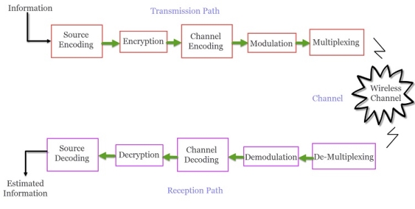
A typical transmission path of a Wireless Communication System consists of Encoder, Encryption, Modulation and Multiplexing. The signal from the source is passed through a Source Encoder, which converts the signal in to a suitable form for applying signal processing techniques.
The redundant information from signal is removed in this process in order to maximise the utilization of resources. This signal is then encrypted using an Encryption Standard so that the signal and the information is secured and doesn’t allow any unauthorized access.
Channel Encoding is a technique that is applied to the signal to reduce the impairments like noise, interference, etc. During this process, a small amount of redundancy is introduced to the signal so that it becomes robust against noise. Then the signal is modulated using a suitable Modulation Technique (like PSK, FSK and QPSK etc.) , so that the signal can be easily transmitted using antenna.
The modulated signal is then multiplexed with other signals using different Multiplexing Techniques like Time Division Multiplexing (TDM) or Frequency Division Multiplexing (FDM) to share the valuable bandwidth.
The ChannelThe channel in Wireless Communication indicates the medium of transmission of the signal i.e. open space. A wireless channel is unpredictable and also highly variable and random in nature. A channel maybe subject to interference, distortion, noise, scattering etc. and the result is that the received signal may be filled with errors.
The Reception PathThe job of the Receiver is to collect the signal from the channel and reproduce it as the source signal. The reception path of a Wireless Communication System comprises of Demultiplexing, Demodulation, Channel Decoding, Decryption and Source Decoding. From the components of the reception path it is clear that the task of the receiver is just the inverse to that of transmitter.
The signal from the channel is received by the Demultiplexer and is separated from other signals. The individual signals are demodulated using appropriate Demodulation Techniques and the original message signal is recovered. The redundant bits from the message are removed using the Channel Decoder.
Since the message is encrypted, Decryption of the signal removes the security and turns it into simple sequence of bits. Finally, this signal is given to the Source Decoder to get back the original transmitted message or signal.
Revolution of Wireless
Photo phone
Electric Wireless Technology
Radio Waves
Revolution
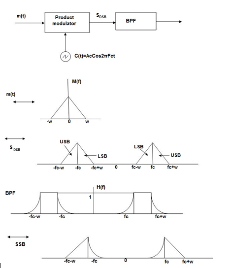
Fig.: GPRS network (1)
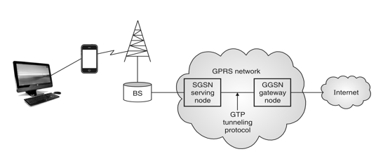
Fig.: GPRS Network (2) (by Peter Rysavy)
Working of GPRS
It manages to send and receive of packet data to and from MS. It is useful for keeping track of mobile devices within scope of service area. It works in mobility management subscribed user verification and provides data required for billing.
It has vital role of routing information whichever is necessary for tunneling Protocol Data Unit (PDUs). To SGSN to Serve Distinct MS. It is on interface for external PDNs. i.e. public data units like internet and X.25.
Charging gateway
GTP
GPRS tunneling protocol uses to encapsulate IP or X.25 packet which are transferred among SGSN and GGSN.
Application of GPRS
GPRS provides many functions among several applications. These are listed below:
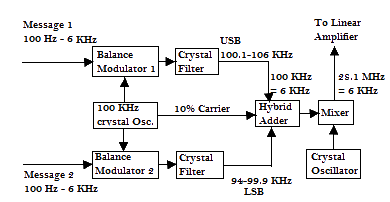
Fig. : GSM Architecture
A GSM system consists of three subsystems:
1. Radio Sub System (RSS)
2. Network and Switching Subsystem (NSS)
3. Operation Sub System (OSS)
In GSM network all radio specific entities are comprised in radio sub systems. RSS consists the two main entities as :
(i) Mobile Station (MS)
(ii) Base Station System
The basic function of RSS is to connect the mobile station to the network. The RSS can consist a number of Base Station Controller (BSC) and each BSC connects to the number of Base Transceiver Systems (BTS) and each BTS connects to a number of mobile stations (MS).
(i) Mobile Station (MS)
A Mobile Station (MS) consists of several functional groups.
(a) Mobile Terminal (MT)
Mobile Terminal offers common functions used by all services. MT transmits through the interface Um.
(b) TA (Terminal Adapter)
Terminal adaptation hides the radio specific characteristics.
(c) Terminal equipment (TE)
A user terminal through which the user receives and sends the data. It can be a headset, microphone etc.
(d) SIM (Subscriber Identity Module)
It is a card inserted into the MS. SIM uniquely identifies the user to the services, stores user parameters and enables the MS to connect to the GSM network.
(ii) Base Station Subsystem (BSS)
BSS have two main components:
(a) Base transceiver station
It connects to a number of mobile stations. The connection between the MS and BTS is established through the Um user interface. Main functions performed by BTS are as follows:
(i) Processing of signals
(ii) Formation of cells
(iii) Amplification of signals
(iv) Frequency hopping
(v) Channel coding and decoding
(vi) Encryption and decryption of data.
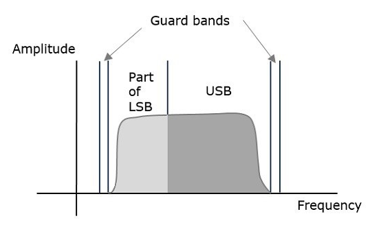
Fig.: MS and BTS connection through Um in GSM cell
(b) Base station controller
It manages a number of BTSS. It uses the Abis interface to connect to various BTSs main functions performed by BSC are as follows:
(i) Processing of signals
(ii) Switching between BTSs
(iii) Controlling BTSs
(iv) Reserving radio frequencies
(v) Frequency hopping and paging.
(vi) Authentication, encryption and decryption of data.
Network and Switching Subsystem (NSS)
The NSS consists of the following databases and switches :
(i) Mobile Services Switching Center (MSC)
(i) Establish the connections to other fined network, such as PSTN and ISDN via Gateway MSC (GMSC) or Interworking functions (IWF).
(ii) Handles all signaling needed for connection setup, connection release and handover of different connections to the other MSCs.
(iii) Call monitoring of MS.
(iv) Supplementary service support such as call forwarding multi-party calls.
(ii) Gateway Mobile Service Switching Centre (GMSC)
This is a MSC which handles connections to other networks like ISDN, PSTN, PSPDN.
(iii) Home Location Register (HLR)
(iv) Visitor Location Register (VLR)
OSS work for the operation and maintenance of the entire network. The main components of OSS are Operation and Maintenance Centre (OMC), Authentication Centre (AuC) and Equipment Identity Register (EIR).
(i) Operation and Maintenance Center (OMC)
(ii) Authentication Centre (AuC)
(iii) Equipment Identity Register (EIR)
Code Division Multiple Access (CDMA) is a sort of multiplexing that facilitates various signals to occupy a single transmission channel. It optimizes the use of available bandwidth. The technology is commonly used in ultra-high-frequency (UHF) cellular telephone systems, bands ranging between the 800-MHz and 1.9-GHz.
CDMA allows up to 61 concurrent users in a 1.2288 MHz channel by processing each voice packet with two PN codes. There are 64 Walsh codes available to differentiate between calls and theoretical limits. Operational limits and quality issues will reduce the maximum number of calls somewhat lower than this value.
In fact, many different "signals" baseband with different spreading codes can be modulated on the same carrier to allow many different users to be supported. Using different orthogonal codes, interference between the signals is minimal. Conversely, when signals are received from several mobile stations, the base station is capable of isolating each as they have different orthogonal spreading codes.
The following figure shows the technicality of the CDMA system. During the propagation, we mixed the signals of all users, but by that you use the same code as the code that was used at the time of sending the receiving side. You can take out only the signal of each user.
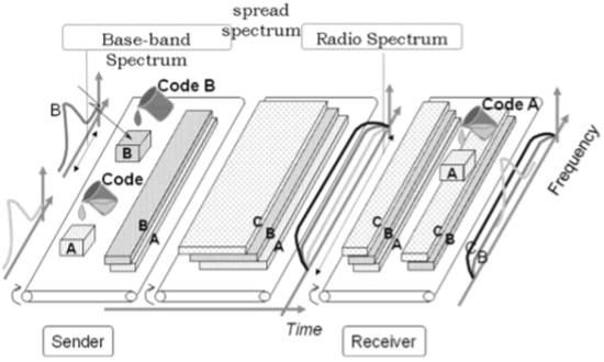
Fig. CDMA
CDMA Capacity
The factors deciding the CDMA capacity are −
Satellite Communication
Satellite communication is the method of transporting information from one place to another using a communication satellite in orbit around the Earth. Watching the English Premier League every weekend with your friends would have been impossible without this. A communication satellite is an artificial satellite that transmits the signal via a transponder by creating a channel between the transmitter and the receiver located at different locations on the Earth.
Telephone, radio, television, internet, and military applications use satellite communications. Believe it or not, more than 2000 artificial satellites are hurtling around in space right above your heads.
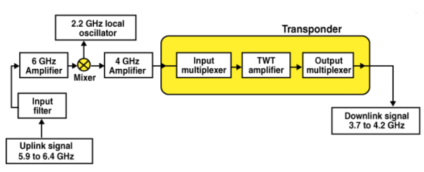
Fig. Satellite Communication
The communication satellites are similar to the space mirrors that help us in bouncing the signals such as radio, internet data, and television from one side of the earth to another. There are three stages that are involved which explain the working of satellite communications. These are:
Let’s consider an example of signals from a television. In the first stage, the signal from the television broadcast on the other side of the earth is first beamed up to the satellite from the ground station on the earth. This process is known as uplink.
The second stage involves transponders such as radio receivers, amplifiers, and transmitters. These transponders are used for boosting the incoming signal and to change their frequency so that the outgoing signals are not altered. Depending on the incoming signal sources, the transponders vary.
The final stage involves a downlink in which the data is sent to the other end of the receiver on the earth. It is important to understand that usually there is one uplink and multiple downlinks
Radar Communication
RADAR is an electromagnetic based detection system that works by radiating electromagnetic waves and then studying the echo or the reflected back waves.
The full form of RADAR is RAdio Detection And Ranging. Detection refers to whether the target is present or not. The target can be stationary or movable, i.e., non-stationary. Ranging refers to the distance between the Radar and the target.
Radars can be used for various applications on ground, on sea and in space. The applications of Radars are listed below.
In any application of Radar, the basic principle remains the same. Let us now discuss the principle of radar.
Basic Principle of Radar
Radar is used for detecting the objects and finding their location. We can understand the basic principle of Radar from the following figure.
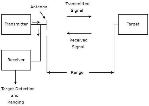
As shown in the figure, Radar mainly consists of a transmitter and a receiver. It uses the same Antenna for both transmitting and receiving the signals. The function of the transmitter is to transmit the Radar signal in the direction of the target present.
Target reflects this received signal in various directions. The signal, which is reflected back towards the Antenna gets received by the receiver.
References
1. Theodore S Rappaport, “Wireless Communications Principles and Practice” Second Edition, Pearson Education
2. John C. Bellamy, “Digital Telephony”, Third Edition; Wiley Publications
3. Thiagarajan Vishwanathan, “Telecommunication Switching Systems and Networks”; PHI Publications
4. Wayne Tomasi, “Electronic Communications Systems”; 5th Edition; Pearson Education
5. Vijay K Garg, Joseph E Wilkes, “Principles and Applications of GSM” Pearson Education
6. Vijay K Garg, Joseph E Wilkes, “IS-95CDMA and CDMA 2000 Cellular/PCS Systems Implementation” Pearson Education
7. Mischa Schwartz, “Mobile Wireless Communications”, Cambridge University Press