Unit - 2
Transmission System
It is the mechanism which transmits the power to the driving wheels which is developed by the engine of an automobile. It is also called Power Train. It constitutes:
• Tyres
• Propeller shaft
• The gear box
• Wheel
• Rear axle
• Universal joints
• Clutch
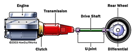
Fig 1 Components of Transmission system.
Requirements: -
• It can sustain the consequence of torque forces, driving thrust and braking force efficiently.
• It provides means to drive the driving wheels at dissimilar velocities when necessary.
• It enables flow of power at 90 (right) angles.
• It must enable transmission of power at different angles and lengths.
• It enables speed reduction between engine and the drive wheels in the ratio of 5:1.
• It offers ways to transmit power in opposed direction.
• It provides a varied leverage between the engine and the drive wheels
• It offers linking and de-linking of engine with other members of power train effortlessly and devoid of shock.
The main units of the transmission system according to the above requirements are as follow: -
• Clutch
• Propeller Shaft and Universal Joints.
• Gear Box
• Transfer Case
• Final Drive
• Differential
• Torque Tube
• Road Wheel
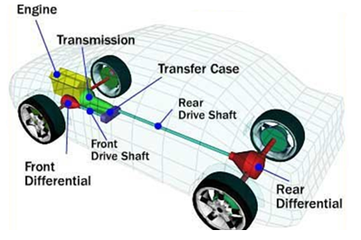
Fig 2 Main units of Transmission System.
A clutch is a device that permits the rotating motion of a shaft to be transferred to another shaft, whose axis coincides with that of the first.
• This device is placed b/w engine and the gears.
• As this device is engaged, power is transferred from the engine to the back wheels through the transmission devices and the automobile starts moving.
• As this device (clutch) is turned off, the power does not reach the wheels and the automobile stands although the engine is still on.

Fig 3 Parts of Clutches.
Disengagement of clutch happens when:
• Starting the Engine
• Gear shifting
• Engine is idling
The clutch is engaged only when the vehicle is to move and is kept on when the vehicle is moving.
Single Plate Clutch (SPC)
- The diagram of SPC is given below in Fig. 4, with the friction plate placed between the flywheel and the pressure plate.
- Springs are provided tangentially offering axial force keeping the clutch in the engaged position.
- The second friction plate is attached on a hub (split from the inside) and thus the gear box is free to slide on the shaft. Friction is encountered from the friction plate on either side to provide two annular friction surfaces for the transmission of power.
- Clutch pedal is also there which pulls the pressure plate against the spring force every time detachment is required. It usually continues to be in engaged position (Figure 4).
- As the pedal is depressed, the pressure plate moves to the right opposite to spring force. This is achieved through a suitable linkage (not shown in Figure 4) and a thrust bearing. As such, the friction plate and clutch are released.
- In real sense, the clutch construction varies. The plate (pressure), springs, releasing lever and cover forms a cover assembly, that can be fixed straightly to the engine block, with the clutch plate placed between the flywheel and the pressure plate.
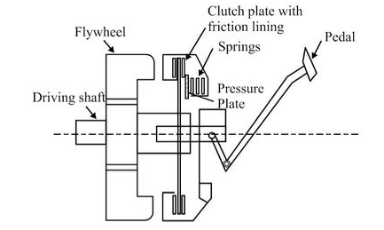
Fig 4 Single Plate Clutch.
Multiplate Clutch (MPC)
• This type of clutch is a modified version of SPC where friction and number of metallic plates are increased.
• Due to growth of frictional surfaces, the ability of the clutch to transmit torque increases.
• The overall diameter of the clutch is reduced for torque transmission similar to a single plate clutch. Hence, MPC is applicable where high torque transmission is required like various heavy automobiles and racing cars.
• This is also used in scooters and motorcycles, due to space limitation.
• The framework is comparable to the SPC, exception being that, the friction plates are in 2 pairs, i.e., one pair of plates slips into the groove on the flywheel and the other a pressure plate slides onto the hub splines. Alternative plates belong to each set.
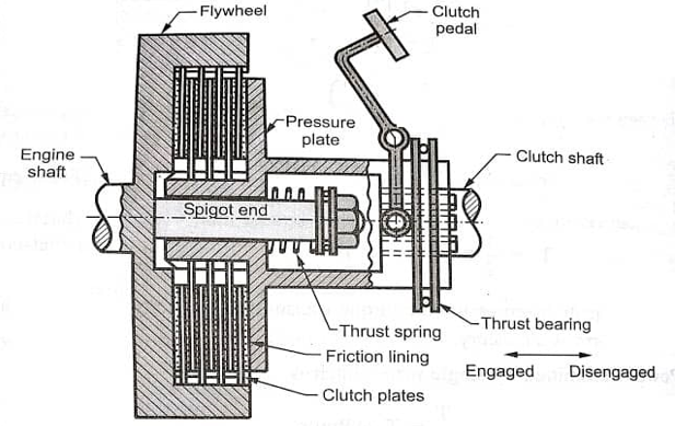
Fig 5 Multiplate Clutch
Working of MPC is divided into 2 steps as discussed below:
Engagement
- As the paddle is pressed, the engagement takes place in the engine and the movements of the thrust springs is enhanced.
- Thrust springs offers pressure to the pressure plates making the pressure plate to move in forward direction.
- Also, the linings which are placed on the inner side of the pressure plate make contact with the flywheel, start its action.
- Consequently, the clutch engages.
Disengagement
- For disengagement of engine and clutch, the clutch pedals as well as the fins of inner splined sleeves are pressed.
- Thrust spring moves in backward direction releasing pressure from the pressure plates and plate also moves backward.
- Consequently, due to released pressure from the flywheel, plate and springs the clutch disengages.
• This is a hydraulic transmission drive which is used to increase the torque of the automobile and henceforth reducing its speed.
• Torque converter provides constant deviation in the ratio of low to high.
• The important feature of this device is its capability to double (multiply) torque when there is a noticeable difference b/w the I/P and O/P rotational speeds comparable to a reduction gear.
• Cars working on automatic transmission have no clutch for disconnecting the transmission from the engine. As such they use this device.
Working
- As the engine switches on, rotation of the impeller starts. High centrifugal forces are generated inside the impellor which forces the oil (hydraulic fluid) into the turbine, turbine is still motionless.
- The hydraulic fluid thus gains high kinetic energy from the engine and knocks the external edges of the turbine. The force of high KE fluid (oil) causes the turbine to rotate. This force gets increased as the engine speed increase.
- When this force become very high, the turbine starts rotating in fruitful manner and the automobile starts moving.
- The turbine blade angle is such that it changes the direction of oil flow so that when it comes out of the turbine at the center, its direction is effectively backwards.
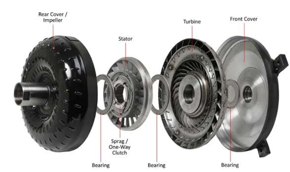
Fig 6 Parts of Torque Convertor
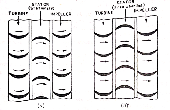
Fig. 7
Fig. Flow of fluid in torque converter (a) under low-speed condition the stator deflects the fluid flow back to the impeller, (b) under high-speed condition the stator free wheels and fluid flow is not deflected.
- Overdrive is an important part of a transmission unit which is attached to the end portion of the gear box.
- It is used to deliver the highest gear O/P with minimal engine I/P hence offering smoother drive and high fuel efficiency i.e., wheel speed greater than engine speed.
- It is an organization of sun and planetary gears which are arranged in a distinct manner.
- When overdrive is engaged, it delivers high rotations/minute to the O/P shaft with low engine rotations/ minute offering smooth, noise free drive and high fuel economy.
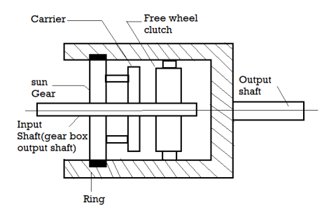
Fig 8 Overdrive.
Working of an Overdrive
- Overdrive in cars can be enabled or disabled using any air, electrical or magnetic actuation methods using buttons.
- Overdrive disabled - In this position, the input shaft passing inside the sun gear rotates the sun gear. This sun gear rotates the attached planetary gears (carrier) and these carriers rotate the annulus and direct drive (input shaft rpm similar to O/P).
- Overdrive enabled – In this position, the sun gear is steadied. The annulus is no longer rotated by the planetary gear. In this case, that the O/P shaft will move with a higher rpm than the I/P shaft due to the higher reduction ratio of the planetary gears and annulus (rings).
• Free wheel in automobile is also called overrunning clutch.
• An overrunning clutch is a clutch that can be automatically connected and disconnected by a relative rotational speed difference or a change in the direction of rotation between the driving and engaged parts.
• The overrunning clutch mainly serves as a mechanical transmission system with two functions.
• First, the overrunning clutch plays the role of a medium to provide variable speed to the driven parts under the constant motion of the driving parts; This is the connection of the kinetic chain to speed conversion.
• Secondly, the driving parts of the unidirectional overrunning clutch can transfer torque only in one direction, not in the reverse direction.
Advantages
- On long downward slopes, an appreciable amount of fuel is saved. The saving may be upto 20 %.
- Less wear on the transmission because whenever the car free wheels, the engine and the gear box are disconnected from the propeller shaft.
- The engine can idle simply by closing the throttle without bringing the gears in neutral Thus gear changing at low speeds is much simplified as the clutch need not be disengaged for this purpose.
Disadvantage
The main demerit is that as there is no resistance due to engine and gear box friction while freewheeling, the brakes must be used more effectively to stop the vehicle on a downward slope. Freewheel is also used as essential component of torque converter in modern automatic transmissions.
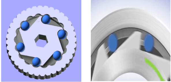
Fig 9 Freewheel Unit.
• A U-joint (universal coupling) is basically a coupling used to connect two rigid rods having axes inclined with each other, and is applicable in shafts which transmits rotary motion.
• RWD automobiles have U-joints at each end of the drive shaft. U-joints linked to the yoke permits the drive shaft to move backward and forward as automobile passes any obstacles or sink in the road, effectively shortening or lengthening the shaft.
• FWD also use 2 joints i.e., constant velocity (or CV) joints which also compensate for steering changes.
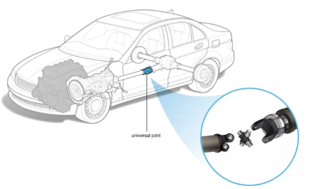
Fig 10. Universal Joint
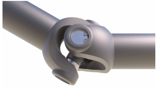
Fig 11 Universal Joint.
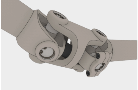
Fig 12 Constant Velocity Universal Joint
The most common type of U- joint is the hook joint (Figure 13) which is highly used as it is very simple and compact in construction and is equitably effective at small angles of propeller shaft movement up and down 18°.
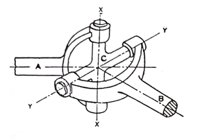
Fig 13 Hooke’s Joint
- The two opposite sides of the cross are supported on the shaft A's yoke, while the other two arms support the cross in the shaft B's yoke.
- The axes of shafts A and B intersect. Each of these shafts has a yoke. Cross four sides.
- Thus, shaft A can have axis XX and shaft B, angular rotation about axis YY. It is thus seen that with the addition of the hook it would be possible to have positive drive allowing angular momentum between shafts A and B.
- Differential gear permits power from the engine to be transmitted to a pair of driving wheels, dividing the force equally between them but permitting them to follow paths of different lengths, as when turning a corner or traversing an uneven road.
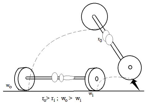
Fig 14 Differential Gear.
When the car/ automobile is moving straight all wheels move and rotate at same speed. As the car is turning, the outer wheels will travel longer distance in comparison to inner wheels (Fig 15). If therefore, the car has a solid rear axle only there are likely chances of tyres to skid.
Hence if this skidding is to be evaded, some mechanism must be used in the rear axle, which must minimize and maximize speed of inner and outer wheels respectively while taking turns and also keeping the speeds of all wheels same while moving straight ahead. Differential is a device which solve the above problem.
This device is used in all modern cars, two-wheel-drive vehicles and also in various all-wheel-drive vehicles, e.g., full-time four-wheel drive vehicles, wherein, besides a differential on each of the axles, an additional differential is also required between the front and the rear axles since the front and rear wheels travel different distances while taking a turn.
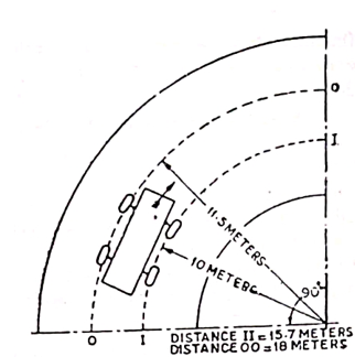
Fig. 15 Distance travelled by inner and outer wheels on a turn.
Working
- When automobile is moving straight, the cage along with the inner gears moves as a single unit and revolve at the same speed. In this case, there is no relative motion amongst the various differential gears.
- When the vehicle turns assuming that the cage is stationary, turning one sun gear will cause the other to rotate in the opposite direction i.e., if right sun gear rotates 'n' times in a particular time, the left sun gear will also rotate n times in the same period but, of course, in the opposite direction.
- Thus, for example, consider a vehicle with wheel speed N r.p.m. Going straight, when it takes a turn toward right. At this time there will be a resistance to the motion of the right wheel and as a result of differential action if the right wheel rotates back at 'n' r.p.m. Then the left wheel will rotate forward at 'n' r.p.m. This will give the resultant speed of the left wheel as (N+n) and that of the right wheel as (N-n) r.p.m.
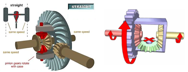
Fig 16 When vehicle is going Straight with same speed.
The larger the amount of friction present in the differential, the larger is the inequality of torques and hence if one wheel of the vehicle with friction in the differential g gets on the e.g., ice, mud or if the wheel gets lifted off the ground while turning at high speeds as in inequality of slippery surface in racing cars, for example, then a larger torque may be transmitted to the other wheel, which has a good grip on the road, than to the slipping wheel.
Thus, the grip of that wheel is utilized; this would not be possible in the absence of friction, it is because of this reason that sometimes friction is introduced in differentials intentionally by employing clutch friction plates between the sun gears and the cage. These plates are loaded by means of dished springs, which are so mounted that loading increases or decreases directly as the torque is varied.
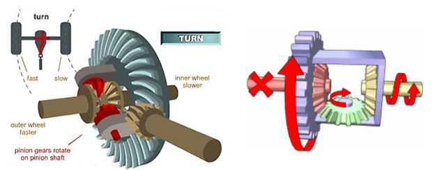
Fig 17. When vehicle us taking the turn (left).
Advantages
- Deliver power from driveshaft to wheels.
- Provides final gear reduction,
- Splits amount of torque passing through each wheel.
- Allow the wheel to rotate at different speed while turning
In AT, the gear ration automatically as the automobile moves, meaning that the driver does not have to shift the gears manually.
Like other transmission systems on vehicles, it allows an internal combustion engine, best suited to run at a relatively high rotational speed, to provide a range of speed and torque outputs necessary for vehicular travel.
The most popular form found in automobiles is the hydraulic planetary automatic transmission. This system uses a fluid coupling in place of friction clutch, and accomplishes gear changes by hydraulically locking and unlocking a system of planetary gears.
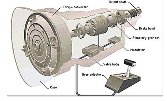
Fig 18 Automatic Transmission System.
Working:
The turbine of the torque converter drives the ring gear of the first gear train through a free wheel. The drive to the ring gear of the second gear train is then taken from the planet carrier of the first train so that the two act in series. This arrangement gives three forward and one reverse speeds. For direct gear, clutch A is engaged. The second gear is obtained by engaging clutch B and applying brake BS. The application of both brakes BS and BF gives the first i.e., the lower most gear. For reverse gear only brake BR is applied.
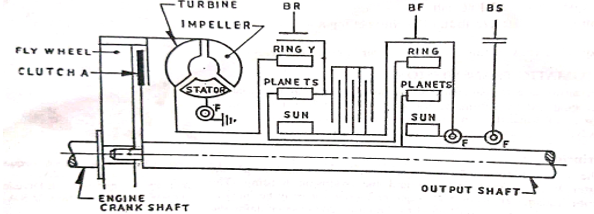
Fig. 19 Working of Automatic transmission.
The selection of the particular gear and application of corresponding clutch and brake is done hydraulically. The hydraulic pressure is regulated by two factors:
(i) car speed that controls oil pressure on one side of the shift valve and
(ii) the throttle opening controlled by the driver through accelerator pedal, which controls oil pressure other side of the shift valve.
It is a dependent system design in which a single shaft is used and all the wheels are connected by this single shaft in lateral direction. This beam axle not transmit power and hence sometimes called a dead axle. In this type of conventional suspension, the outcome on one wheel is directly transferred to another side wheel through the axle.
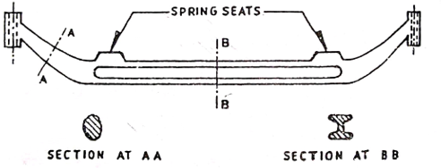
Fig 20 Front Axle
This type of axle is no more used in modern cars, although it is still being used in heavier vehicles. The steels used for this are 0.4 per cent carbon steel or 1.3% nickel steel.
A downward sweep is given to the centre portion to keep a low chassis height. The main axle beam is connected to the stub axles by means of kingpins, shown in Fig. 21. The front road wheels are mounted on these stub axles.
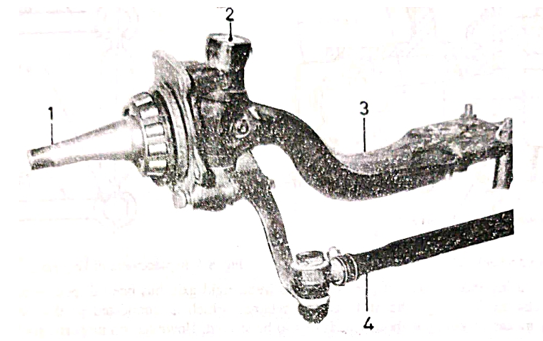
Fig 21 Stub Axle Connection.
1.Stub Axle 2. King pin 3. Front axle 4. Tie rod
Stub axle can be any of the four types shown in Fig. 22. Reversed Elliot type is widely used. Stub axles are made of 3 per cent nickel steel and alloy steels containing chromium and molybdenum.
The front wheel stub axle assembly is clearly shown in Fig. 23. The wheel revolves over two ball bearings, which can be adjusted by means of an adjusting nut as shown. Oil seals are provided to prevent the leakage of lubricant from the bearings.
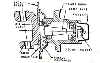
Fig 22 Front wheel stub Axle Assembly.
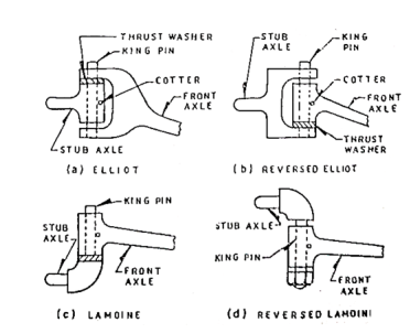
Fig 23 Types of stub axles.
- Steering system, in automobiles is used to control the direction of a vehicle's motion. Because of friction between the front tires and the road, especially in parking, effort is required to turn the steering wheel.
- To lessen the effort required, the wheel is connected through a system of gears to components that position the front tires.
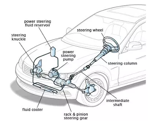
Fig 24 Steering System.
- The gears give the driver a mechanical advantage, i.e., they multiply the force applied by the driver, but they also increase the distance through which the driver must turn the wheel in order to turn the tires a given amount.
- Various types of gear assemblies, none with any decisive advantages over the others, are used, although some manufacturers prefer a rack-and-pinion system.
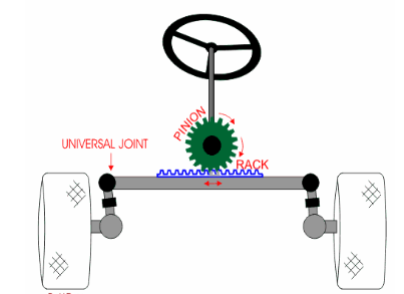
Fig 25 Steering System.
- Ackerman steering geometry is a geometric arrangement of linkages in the steering of a car or other vehicle designed to solve the problem of wheels on the inside and outside of a turn needing to trace out circles of different radii.
- The intention of Ackermann geometry is to avoid the need for tyres to slip sideways when following the path around a curve.
- Intersecting the axes of the front wheels on this line as well requires that the inside front wheel be turned, when steering, through a greater angle than the outside wheel.
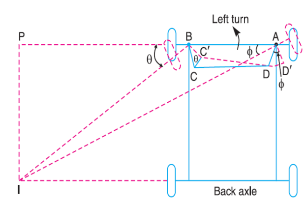
Fig 26 Ackerman steering geometry
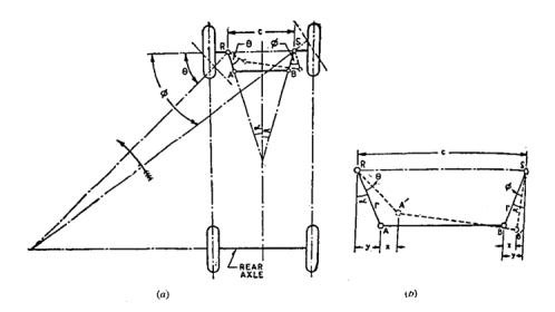
Fig 27 Ackermann steering mechanism.
(a) Outline of mechanism
(b) Details of enlarged scale
Let l = length of track rod, and
r = length of links RA and SB
Then referring Fig. 27 (b) and neglecting the obliquity of the track rod in the turned position, the movements of A and B in the horizontal direction may be taken to be same (each equal to 'x')
Then, sin (α + θ) = (y + x)/r
And, sin (α – φ) = (y – x)/r
On adding,
Sin (α + θ) + sin (α – φ) = 2y/r = 2sin α
The mechanism gives only 3 positions for correct steering; one when θ = 0 and the other two each corresponding to the turn to right or left (at a fixed turning angle). However, for other angles also it gives a close approximation to the ideal condition.
Further this has the advantage that it employs pivots and not sliding constrains, due to which reason its maintenance is easier. That is why it is universally employed. However, lately the automobile designers do not care to follow the Ackermann mechanism very strictly on account of the improvement in the suspension and tyres.
Any small deviation from the true rolling angles can be readily corrected by the tyres sidewall flexibility and tread distortion. Rather it is endeavored to obtain the smallest value of the turning circle.
It may be noted that while parking, it is easier to steer a vehicle in reverse than in the forward direction because the rear wheels turn on smaller radius than the front wheels.
Example
The front axle of a car has pivot centres 1 1 m apart. The length of each steering arm is 150 mm, while the track rod is of 1.0 metre length. Calculate the wheelbase for perfect rolling of the car wheels when the inner wheel stub axle is at 55° to the rear centre line.
Solution.
Referring fig. 27(a),
θ = 90 – 25 = 35°
r = 150mm = 0.15m
l = 1.0m
c = 11m
Sin α = (c - l)/2r = (1.1 - 1.0)/ (2 x 0.15) = 0.333
α = 19.45°
From Equation (8.6),
Sin (19.45° + 35°) + sin (19.45° - φ) = 2 sin 19.45°
i.e. 0.814 + sin (19.45° - φ) = 0.667
φ = 27.9°
From equation of correct steering,
Cot φ – cot θ = c/b
Cot 27.9° - cot 35° = 1.1/ b
1.888 – 1.428 = 1.1/b
Wheel base, b = 2.39m
- Caster angle, is the top to bottom angle of the steering axis and suspension components as they meet the wheel.
- A zero/neutral caster setting would result in a perfectly vertical spring/shock with the center of the wheel positioned directly “south” of the strut mount or upper ball joint (depending upon the vehicle suspension type).
- Caster angle is an alignment adjustment that occurs on the turning wheels only, i.e., the front wheels of a vehicle.
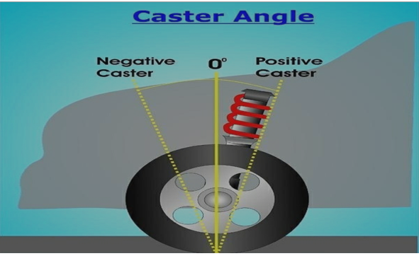
Fig 28 Castor Angle.
- Positive caster positions the lower ball joint in front of the upper ball joint or strut mount. This results in the tire contact patch hitting ground in front of the steering system and suspension components.
- Negative caster positions the lower ball joint behind (rearward of) the upper ball joint or strut mount. Unlike in a positive caster arrangement, the wheel and tire contact patch hit the ground behind the steering system and suspension components.
- Negative caster angle isn’t a setting used by modern road cars. The self-aligning torque and straight-line stability that is characteristic of positive caster, are absent in a negative caster setting. In fact, a “loose” steering wheel and immense front wheel instability would result from a negative caster setup.
• Camber is the angle at which the wheel and tire stand relative to the road – assuming it is perfectly flat.
• The easiest way to envision what camber looks like is to view the wheel and tire head on.
• When stationary, the tire maintains a static camber angle, whereas when the car is cornering, due to body roll, the contact patch is reduced. In order to counteract this effect and have the greatest amount of tire on the road while cornering, camber settings must be taken into consideration and adjusted accordingly.
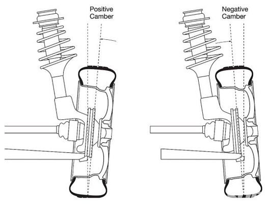
Fig 29 Camber Angle.
Positive camber
Positive camber means that the top of the wheel is pointed outwards rather than the inside. In other words, the wheels are pointing away from the vehicle’s chassis. Before discussing the negative chamber, let us consider how positive camber can affect the car tires.
Effects
One of the most visible impacts of positive camber is that it provides stability. Therefore, it can steer in any direction without much effort. Positive camber can be found mostly on recreational vehicles and agricultural vehicles such as tractors. Moreover, if you are driving on an uneven surface, positive camber will provide the much-desired stability.
Most of the front-wheel-drive vehicles have a non-adjustable camber. However, it does not affect the everyday driver as their only concern is a smooth and comfortable ride. In case of an accident or other damage, the wheel components must be replaced. For optimal performance, the original positive camber must be recreated.
However, it is easier said than done. Recreating an original positive camber for the wheels can be quite tricky and, in some cases, nearly impossible.
Negative camber
Negative camber is when the wheels are inclined towards the chassis of the car. If you are someone who opts for high-speed cornering, then the negative camber is the ideal camber type for you. The angle allows making high speed cornering a breeze. It is made possible as the bottom part of the tires do not come into contact with the surface as much.
The reduced contact with the road surface drastically reduces the pressure on the tires. Hence, it makes high-speed cornering feel like a breeze. Negative camber can be found in F1 racing and other motorsport events. Owners of high-performance cars also prefer to have negative camber.
Effects
As discussed above, negative camber drastically improves the handling of the vehicle. Apart from this, it drastically reduces the vibrations in the wheel. However, there are drawbacks to negative camber as well. One of the drawbacks is that straight-line acceleration will be drastically reduced. The reason is that the angled wheels will need to work harder to reach higher speeds.
Another drawback is that the braking distance will increase, meaning that you will require a greater length of road to bring a vehicle to a stop. You are also more likely to wear out the tires quicker because of the way the wheels are angled. Another drawback is that a negative camber reduces traction on wet surfaces.
Wheel toe-in is an angle formed by the centerline of the wheel and the vehicle's longitudinal axis, when viewed from above, the sum of the toe values for each wheel gives the total toe value.
When the extension of the wheel center lines meets in front of the vehicle's direction of travel, it is known as tow-in.
If the lines meet behind the vehicle's direction of travel, it is known as a tow-out.
When the extensions to the wheel center lines are parallel, this is referred to as the zero position, the toe value is rarely given by the manufacturer in degrees, and it is common to give the value expressed in mm which is the point of the circle. Measures the difference in mm between the wheels. Two measurements are taken at the front and rear of the wheel hub, half the distance from the ground to the top of the wheel.
Effect
In a rear-wheel drive vehicle, the rear axle pushes the front axle tyres as they roll along the road. Tyre rolling resistance produces some drag which results in rearward movement of the suspension arms against their bushings.
Due to this, most rear-wheel drive vehicles are provided with some toe-in to compensate for the movement so that the tyres run parallel to each other The case of the front-wheel drive vehicles is just the opposite, wherein the front axle pulls the vehicle through itself (front axle), resulting in forward movement of the suspension arms against their bushings to compensate which negative toe-in, i.e., toe-out is provided.
Toe amount also affects the handling characteristics. Increase in toe-in would result in decreased oversteer and increased directional stability at high speeds, whereas increase in toe-out would result in reduced understeer and greater ease in steering during cornering.
Amount Toe-in initially provided generally does not exceed 3 mm.
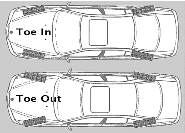
Fig 30 Toe – in And Toe – out
Understeer and oversteer are vehicle dynamics terms used to describe a vehicle's sensitivity to steering.
Oversteer occurs when a car turns (steers) more than the amount directed by the driver.
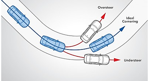
Fig 31 Understeer and Oversteer in a vehicle.
Factors affecting Oversteer and Understeer
1. Passive factors
- Weight distribution. If the vehicle weight is biased towards the front axle, it would cause oversteer, while understeer would result due to weight bias towards to rear axle.
- Type of drive and engine placement.
- Rear wheel drive, engine at the front. Engine placement at the front results in greater grip at the front, viz., relatively lower grip level at the rear which would result in oversteer, especially when accelerating while cornering. Even very small weight transfer from the front to the rear occurs on acceleration since there is much less grip available for that during cornering, due to which the net result would remain oversteering.
- Rear wheel drive engine also at the rear. Such a vehicle, e.g., Porsche 911 also has a tendency to oversteer due to a different reason. Due to the engine being at the rear, the momentum of the vehicle rear is more than the front which means it is harder for the rear to change direction and this leads to oversteer particularly when braking during corner. This may occur in spite of the weight bias to the rear on account of engine placement.
- Front wheel drive with front engine. Examples of such vehicles are Peugeot 205 GTI and Renault Clio Cup. Such cars are also subject to oversteer due to engine placement, but it is usually possible to accelerate out of the oversteer situation, by rearward weight transfer due to acceleration, which increases grip at the rear, decreasing the oversteering tendency.
- Four-wheel drive. In this case there is less risk of oversteer due to over-speeding on account of sharing of drive forces over all four wheels.
III. Suspension and chassis setup. Depending on the arrangement and design, there may be oversteer or understeer.
IV. Tyre type and pressure. These may influence the adhesion at the front or rear wheels and accordingly oversteer or understeer may result.
2. Active factors
- Cornering speed. Entering the corner too fast increases the tendency to oversteer.
- Throttle position. It the engine is powerful and you press the pedal too hard, you would oversteer Similarly lifting the foot from the pedal in the midst of the tum, there would be forward weight transfer due to which rear wheels would lose traction resulting in oversteer. In front wheel drive vehicles, pressing the accelerator pedal again can help to reduce oversteer.
Out of these two, understeer is comparatively less undesirable, though both an unwanted, because the driver reacts naturally and positively by steering in the desired direction. In the case of oversteer, he is always conscious of losing the control and therefore greater care is required. That is why many more powerful have on-board computer systems which can automatically brake the wheels or override the cars driver's throttle inputs to prevent an oversteer condition.
However, in many sports cars, there is a provision to allow such system to be turned off completely by experienced drivers so that they may oversteer on purpose while negotiating curves at high speeds.
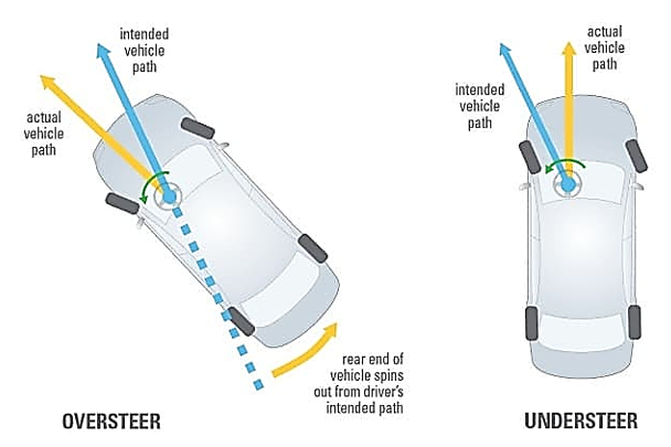
Fig 32 Understeer and Oversteer
Due to this reason, generally the vehicles are designed to provide understeer conditions at normal speeds. But at higher speeds, the situation changes first to neutral steer and then to oversteer. That is why at higher speeds where the driver has less time to take corrective action, a sharp transition from understeer to oversteer is particularly dangerous.
In fact, in oversteering vehicles, this transmission is characterized by an instability mode, called the critical speed. As this speed approaches, the steering becomes gradually more sensitive, till at critical speed, the yaw velocity gain becomes infinite, which means the vehicle will continue to turn with the wheel straight ahead. Understeering cars do not suffer from this disadvantage. That is why high-speed cars are usually set up to understeer.
Most of the drivers have a natural tendency to lift their foot off the accelerator pedal during loss of steering control due to oversteer, which is the exactly opposite of what is desirable in case of a rear-wheel drive vehicle Releasing the throttle causes the car to pitch forward causing weight transfer from rear to front, aggravating the oversteer and reducing the traction even further.
Regarding brakes, firstly for braking the driver has to lift his/her foot off the accelerator pedal, aggravating oversteer as explained above, and secondly during braking there is weight transfer from rear to front again adding to oversteer. Yet, most modern cars are given a brake bias which counteracts the tendency to oversteer on applying brakes.
Oversteering is preferred in racing cars, which enables the driver to accelerate early as the car passes the apex of a corner, thus gaining extra speed on the following straight.
Fig 33 shows a simplified view of the live rear axle of a front engine, rear driven automobile. The drive from the propeller shaft comes to the pinion shaft which is supported in bearings in the axle casing.
The crown wheel is in mesh with the pinion and is mounted on shaft on the ends of which are fixed the caps which serve to restrict the wheels in axial direction. The wheels are mounted on bearings on the ends of the axle shaft. In practice, however, there are two half shafts instead of single one shown here.
The weight of the body and load due to occupants is transmitted through springs to the axle casing. The casing itself is supported by road wheels.
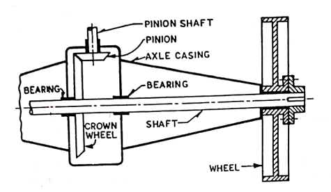
Fig. 33 Rear Axle
Live axle is very big and heavy. It consists of the differential, drive shafts, leaf spring and a tube enfolding all things. Since the whole axle is rigidly fixed to the wheels the Unsprung weight is very high. Without the driving mechanism incorporated, dead axle has much less unsprung weight, so its ride quality is better than a Live Axle.
Unsprung weight is the part of the vehicle that is not riding on top of the suspension, likes the wheels, tyres etc. Unsprung weight is a highly undesirable attribute in suspension design, because with less amount of unsprung load the suspension is able to react faster to humps rather than simply transmitting the shock to the cabin.
The ratio of sprung to unsprung weight is a decisive factor in deciding how smoothly a car ride. A heavier car rides better than a lighter car? It is because the heavier car most likely has a higher sprung to unsprung weight ratio than the lighter car. This also means that lighter cars can be made to ride better than heavier cars if they manage to keep their unsprung weight down. And it also explains why these heavy off roaders still ride so roughly while handling so poorly compared to cars much lighter than them.
Compared to the latest independent suspension, a live axle system has the entire differential assembly, tubing and final driveshaft’s as unsprung masses although the main driveshaft is partly sprung. All current independent suspension has the final driveshafts partially unsprung and main driveshaft(s) and differential assemblies are sprung masses attached to the body. Thus, one can see how much of an unsprung weight penalty there is by using a live axle.
In an RWD car, the rear axle is a live axle and front axle is a dead axle. While in an FWD car it is inverse that is front axle is a live axle and rear axle is the dead axle.
- In all drives employed for the rear axle, the spring takes the weight of the body. Several drives are used, two of the most important of which are the Hotchkiss drive and the torque-tube drive.
- Hotchkiss drive is the simplest and most widely used type of rear axle drive. In this case, the spring takes the torque response in addition to taking the weight of the body, driving thrust and side thrust.
- The propeller shaft is provided with two universal joints and one sliding joint. The spring is rigidly fixed in the middle, to the rear axle.
- The front end of the spring rests firmly on the frame, while the rear end rests in a shackle. Driving thrust is transmitted to the frame by the front half of the springs.
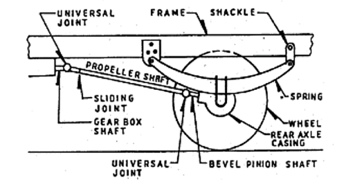
Fig 34 Hotchkiss Drive.
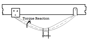
Fig 35 Bending of spring under torque reaction.
- The spring is deflected due to the moment reaction as shown in Fig. 35. Thus, the torque response is taken by the springs.
- Similarly, the springs will deflect in the opposite direction to raise the braking torque. When the springs are deflected in the manner shown, the bevel pinion shaft also changes its position. So, if there is only one universal joint on the front end of the propeller shaft, it will bend in this position.
- To avoid this, another universal joint is used at the rear end of the propeller shaft, when the rear axle moves up and down, it has to rotate in a circle with the front spring support on the frame as the center Is.
- But for propeller shaft motion, the center is in front of the universal joint. This means that during this movement of the rear axle, the length of the propeller shaft must be much greater. This is provided by means of a sliding joint in the propeller shaft.
- In torque tube drives, the spring supports only the thrust in addition to supporting the weight of the body.
- Torque reactance, braking torque and driving thrust are taken by another member called torque tube.
- One end of the torque is attached to the axle casing, while the other end, which is circular in shape, fits into the cup attached to the frame.
- The torque tube surrounds the propeller shaft. The torque tube takes the torque reaction.
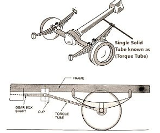
Fig 36 Torque – tube Drive.
- The centerline of the bevel pinion shaft will not shift and will always pass through the center of the spherical cup if the propeller shaft is connected to the gear box shaft via a universal joint located in the center of the spherical cup
- In this case, no universal joint is required at the rear and on the propeller shaft. Also, no sliding joints have been added because in this case both the pinion shaft and the propeller shaft will rotate about the same centre, i.e., about the center of the circular cup. Obviously torque response and driving thrust torque is taken by the tube.
- Important note- In both types of drives the side thrust is taken by leaf spring. If, however, coil springs are used, they are not able to take the side load and, therefore, a separate member is employed in that case. Such a member is usually in the form of a rod of a transverse radius almost parallel to the wheel axis. One end is mounted to the axle casing and the other to the chassis frame. Such rods are commonly called Panhard rods.
References:
- Automotive Engineering- Hietner.
- Automobile Engineering - Narang.
- Automobile Engineering – Dr. Kirpal Singh
- Automotive Mechanics- Crouse.