Unit 1
Basic Equations of Elasticity
Elasticity-When a force is applied on a body then the body goes under deformation and when we remove the force body regains its original shape and size, this property to regaining is called Elasticity of the body. And the applied force is called deformation force.
Stress-When a body is under deformation due to deformation force then a resistive force F comes, which oppose the tendency of deformation this resistive force per unit area is called stress. Stress is equal to the applied deforming force. And stress is represented by σ. Unit of stress will be Newton/ m2.
σ = F/A

Fig. 1.1 Longitudinal stress
Strain- Strain is defined as the ratio of change in dimension to the original dimension.
Strain = ΔL/L
To understand the relationship between stress and strain we plot a graph with different-different load and corresponding stress and strain. The sample is given bellow-
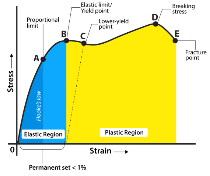
Fig. 1.2 Stress-strain Relation
1.3 Equation of equilibrium
 Let us consider a cube element inside the body under stress-
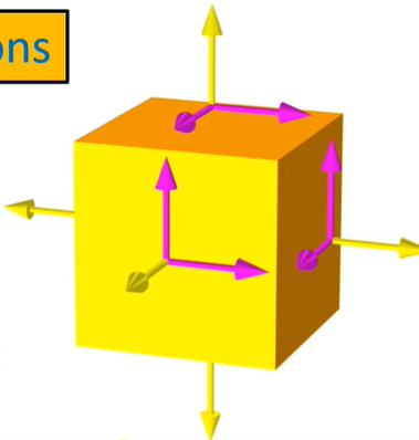
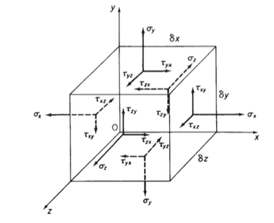
Fig. 1.3 All stress on an element
Assumption – shear stresses are complementary means self-balanced.

 Now the stress matrix-
σ yx σ yy σyz
σ zx σ zy σzz
For equilibrium ∑Fx = 0, ∑ Fy = 0, ∑ Fy = 0
First we put all x-component equal to zero-
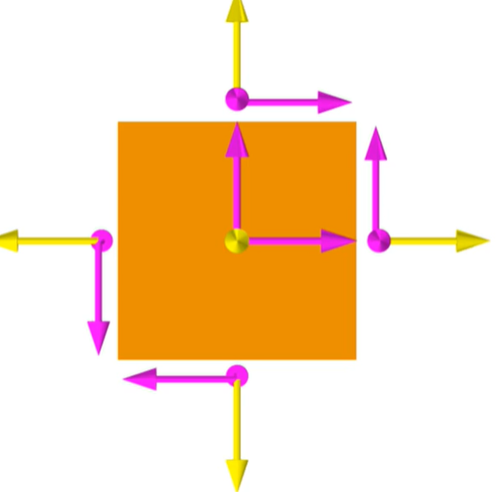
Fig. 1.4 2D view of stress
The dimension of this cube is Δx, Δy, Δz.
Now for the equilibrium condition, the same forces should be zero.
∑ Fx = 0


This is the first equilibrium equation finding by x component of forces, similarly, we will get the following two-equation by equating some of the y components and z components zero-


Equations 1, 2, and 3 are known as the equation of equilibrium.
1.4 Compatibility Equations
It has been seen that displacement of a point within a solid body can be represented using a displacement vector u, the component of u is ux, uy, and uz.
Now the deformation at a point can be represented by Six strain components-
ϵxx, ϵyy, ϵzz, γxy, γyz, γzx
By Cauchy Equations-

It is easy to find out six strain components differentiating three displacement components according to Cauchy but if we know the six strain component and want to know three displacement components then it will be very tough to found this three-component by integrating six strain components. To make easy this task we use compatibility equations also known as continuity equations. These compatibility equations can be divided into two groups-
The first group behave

we differentiate the first two of the above-


By adding these two we get-

Similarly by considering εyy  and γyz and εzz, εxx and γzx we will find two more equation of this group-


To findings the second group we use the following equation-


Differentiating above-


By adding the last two-equation subtracting the first-
Differentiating once more the above equation wrt z
This is one equation of the second group, similarly, we can get the remaining two-equation also-


Equation 1, 2, 3, 4, 5 and 6 are six compatibility equations.
1.5 Boundary Conditions
In the mechanics of solid, there are many complex equations to solve these equations we use boundary conditions only proper boundary condition can solve the equation easily. Boundary condition can be specified on the surface of the body in the following three ways-
1- Tractions on the surface.
2- Displacement of the surface.
3- Displacement and Traction both on the surface.
Example- cantilever beam
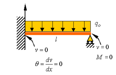
Fig. 1.5 Boundary condition on a cantilever beam
1.6 Saint venant’s Principle
According to this principle, failure occurs when the maximum strain in the complex stress system becomes equal to the yield strain of the system. For no failure-

Where ϵy is yield strain
Principle stress- A plane on which the shear stress is zero and direct stress is normal to the plane is called principle plane and the stress on the principle plane is called principle stress.

Fig. 1.6 Principle plan
MAXIMUM PRINCIPLE STRESS THEORY- According to this theory the failure occur when the maximum principle stress becomes greater than ultimate/yield stress.
Maximum principal stress (1)> failure stresses (Syt or Sut)
1.7 Stress Ellipsoid
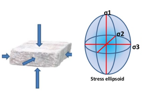
Fig. 1.7 Stress Ellipsoid
When stress is imposed on a body and resolved in three mutually perpendicular axis. These axis are called principle axis of stress, generally, these three axis are
in equal.
It is also known as Lame stress Ellipsoid.
We know that stress vector at a point –
For i=1:
For j=1, 2, 3:
For i=2:

For j=1, 2, 3:
For i=3:
 =
= 
For j=1, 2, 3:
 =
=  …………………………. (4)
For Principle Stresses:

and

Putting these values in eqn. (2) , eqn. (3), and eqn. (4), we get
 …………………. (5)
 ………………. . (6)
 ……………………. . (7)
Now, squaring and adding eqn. (5), eqn. (6) and eqn. (7), we get

This is a lame ellipsoid equation.
The characteristics equation of the stress matrix is –

The roots of the above equation do not depend on the selection of coordinate axis therefore I1, I2, and I3 must be independent of coordinates, hence they are called stress invariants. If stress matrix is given as-
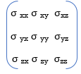
then invariant I1 = σxx + σyy + σzz
and:
I2 = minor of σxx +minor of σyy +minor of σzz
And:
I3 = Determinant of stress matrix
These I1, I2 and I3 stress invariants.
Key Takeaway


2. Compatibility Equations


3. Saint venant’s Principle

4. lame ellipsoid equation

REFERENCES-


