Unit – 5
Pumps
- Based on Working Head:
- Low head pumps (up to 15m). Usually, they do not have guide vanes.
- Medium head pumps (15 to 40m). These usually are provided with guide vanes.
- High head pumps (above 40m). These are multistage pumps.
2. Based on type of Casing:
Casing is designed with the motive of decreasing the loss of kinetic head to minimum.
Based on various shapes of casings, centrifugal pumps can be classified as:
- Volute pump or constant velocity pump:
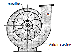
Figure shows a centrifugal pump with a volute or collecting passage round the impeller of gradually increasing area from cut water at A to delivery pipe at B. The cross-section is so designed to give a constant velocity in the volute of spiral shape. For this reason, it is also called as constant velocity volute. In such a volute casing the loss of energy is considerably reduce compared to a circular casing if employed. However, the conversion of kinetic energy into pressure energy is not possible. Due to this the efficiency of pump only increases slightly.
b. Vortex or variable velocity volute pump
An improvement of the design of volute pump shown in Figure. This pump has relatively larger overall diameter compared to pump shown in previous figure in order to provide an annular space between the impeller and volute passage.
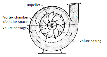
In this annular space called vortex chamber, there is a free vortex in which the velocity of flow of liquid falls as it passes into this chamber from impeller outlet to entry of volute passage. (Since in a free vortex, the velocity of whirl proportional to radial distance). Due to decrease in velocity the pressure increases radially from center outwards. The drawback of this arrangement is that to get an efficient chamber the dimensions become excessive and the pump becomes bulky and expensive. The volute pumps and vortex volute pumps are single stage pumps with horizontal shaft.
c. Diffuser or turbine pump
Figure below shows a diffuser or turbine pump which is similar to vortex volute pump, but a diffuser ring with guide vanes is fixed in annular space.
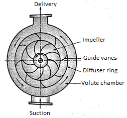
Function of guide vanes is to guide the liquid leaving the impeller in streamlined diverging passages into the volute chamber from where it flows to the delivery pipe. In case of multistage pumps, the liquid from volute chamber flows into the eye of impeller of the next stage pump and the final stage volute discharges into delivery pipe. This pump with diffuser ring becomes in fact a reversed reaction turbine and is commonly known as a turbine pump.
The guide vane passages so formed have an increasing cross-sectional area which reduces the velocity of flow; hence, the partial kinetic energy of the liquid is converted into pressure energy. Further conversion of kinetic energy into pressure energy takes place in the volute chamber of increasing cross-sectional area.
3. Based on liquid handling (Types of impeller)
Depending on the type and viscosity of liquid to be handled, a pump uses three types of impellers, accordingly the pumps are classified as follows:
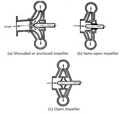
- Shrouded or enclosed impeller
In this type of impellers, the vanes of impeller are cast between two circular discs or plates (shroud) as shown in Figure. The plate on entry side is called crown plate and the plate on back or shaft side is called base plate. This arrangement provides better guidance for liquid to flow and prevents leaking of liquid from blade tips from one passage to another passage with high efficiency. These types of impeller pumps are mostly used for clear water or for other liquids of low viscosity free from dirt.
b. Semi-open impeller
These impellers have a plate only on back side called based plate as shown in Figure. Such an arrangement helps in dealing liquids mixed with fibrous materials. Therefore, these types of impellers can be used in sewage installation, sugar and pulp industry etc. with small amount of debris.
c. Open impellers
These types of impeller do not have any cover plate on either side of the vanes. Therefore, the vanes of an open impeller are open from both sides as shown in Figure. Open impellers are not so efficient but they we useful to deal with liquids which may contain suspended solids such as sand, grit, clay etc. since these pumps do not clog.
4. Based on relative direction of flow through Impeller
Based on relative direction of flow through Impeller, the pumps are classified as:
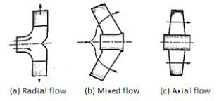
- Radial flow pumps
Most of the centrifugal pumps are radial flow type in which the liquid flows in the impeller in radial direction only as shown in Fig (a). In radial type of impellers, the liquid enters at the center of impeller axially and then it flows radially over impeller blades up to outer periphery. In this the pressure head is developed due to centrifugal force impressed upon the liquid.
b. Mixed flow pumps
Refer Fig (b). It is the modification of radial flow impeller in which the flow is the combination of axial and radial flow and the impeller resembles the propeller of a ship. These are also called as screw pumps due to their resemblance to shape of a screw.
The mixed flow impellers have large discharge rates of liquid compared to radial flow impellers at low heads. Therefore, these types of pumps are suitable for irrigation applications.
c. Axial flow pumps
In axial flow pumps the direction of flow of liquid through its impeller is in the axial direction only from inlet to exit as shown in Fig c. These pumps are designed for very large discharge rates at low heads; hence these are ideally suited for irrigation purposes. The pressure head developed in axial flow pump is not due to centrifugal action, rather it is due to flow of liquid on blades of aero foil section similar to generation of lift by the wings of an airplane. These pumps have adjustable blades similar to Runner blades of a Kaplan turbine.
5. Based on number of entrances to Impeller:
Centrifugal pumps based on number of entrances to the impeller can be classified as follows:
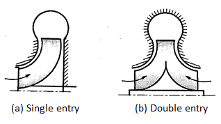
- Single entry pimp
In this pump the liquid enters only from one side into the impeller from suction pipe as shown in fig a. They are also called as single suction pump.
b. Double entry or double suction pump
Refer Fig b. In these pumps entry to impeller is from both sides of impeller. In such pumps the axial thrust is negligible. It is suitable for large discharge rates.
6. Based on number of impellers per shaft:
Based on number of impellers used per shaft, the pumps are classified as:
- Single stage pump:
It has one impeller and it is suitable for heads up to 40 m.
b. Multistage pump:
These pumps use two or more number of impellers in series depending upon the head requirements. In these pumps, the discharge of one pump from casing enters into the eye of impeller of the next pump in series. Total head developed by multistage pump is equal to algebraic sum of heads developed by each pump.
7. Based on shaft position:
Based on shaft position, the pumps are classified as:
- Horizontal shaft pump:
Usually the centrifugal pumps are with horizontal shaft.
b. Vertical shaft pump:
These pumps are designed for specific applications and to save space. e.g. The deep well and marine pumps.
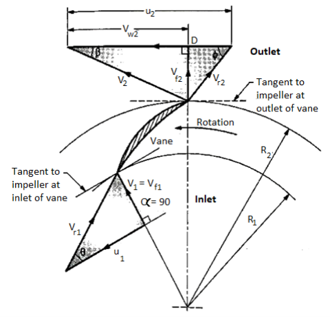
V1, V2 = Absolute velocity of water at inlet and outlet,
Vr1, Vr2= Relative velocity of water at inlet and outlet,
α, β = Angle made by absolute velocity ( V1 ) at inlet with the direction of motion of vane,
θ = Angle made by relative velocity ( Vr1 ) at inlet with the direction of motion of vane, and, are the corresponding values at outlet.
Because the water enters the impeller radially, the absolute velocity of the water at the inlet is radial, resulting in angle α = 900 and Vw1 = 0.
A pump is a power absorbing device in which the work is done by impeller on water. The inlet and outlet velocity diagrams are shown in figure. They can be drawn similarly as those for inward flow reaction turbine. in pumps, the water enters the impeller at its center and leaves at its outer periphery.
Following assumptions are made:
- Liquid enters the vane radially for best efficiency. (α = 90°). Therefore, V1 = Vf1 & Vw1 = 0.
- Liquid enters and leaves the vane without shock.
- The velocity distribution in passages between vanes is uniform.
Let, D1 = Diameter of impeller at inlet = 2 x Radius, R1
D2 = Diameter of impeller outlet = 2 x Radius, R2
N = Speed of impeller in rpm.
The tangential blade velocity at inlet, u1 and at outlet u2 can be written as
U1 = ω R1 = (2πN / 60) R1
U2 = ω R2 = (2πN / 60) R2
V = Absolute velocity
Vr = Relative velocity
Vf = Velocity of flow
Vw = Velocity of whirl
Suffix 1 and suffix 2 represent the velocity at inlet and outlet respectively.
Also, α = Angle made by absolute velocity V1 at inlet
Θ = Inlet angle of vane
Φ = Outlet angle of vane
And β = discharge angle of absolute velocity at outlet.
Work Done (WD) by impeller on water per N weight of liquid per second is given as,
WD = (1 / g) (Vw2 u2 - Vw1 u1) (1)
The above equation is called as Euler’s momentum equation for centrifugal pump.
But Vw1 = 0, since the entry is radial.
∴ WD = Vw2 u2 / g (2)
In case working liquid is water and the weight of water is w, then the work done on water per second becomes,
W-D/s = w x Vw2 u2 / g = ρ.Q. Vw2 u2 (Nm/s) (3)
Where, Weight of water/s,
w = ρ.g.Q (4)
Discharge rate,
Q = Area x Velocity of flow
Q = π D1 B1 Vf1 = π D2 B2 Vf2 (5)
Where, B1 and B2 is width of impeller at inlet and outlet respectively.
Various efficiencies related to centrifugal pumps are as follows:
- Mechanical efficiency, ηm
The ratio of power available at the impeller or power delivered by impeller to liquid to the power input at the shaft (motor power or shaft power) is known as mechanical efficiency.
∴ ηm = Power available at impeller, P(kW) / Shaft power, Ps (kW)
But, power available at impeller is given as, P = ρ (Q+q) Vw2 u2
ηm = {ρ (Q+q) Vw2 u2} / Ps = (Ps - Pmech losses) / Ps
Where, q = leakage loss
2. Manometric efficiency, ηmano
It is defined as the ratio of manometric head, Hm developed by the pump to the head imparted by the impeller to liquid. Mathematically,
∴ ηmano = Manometric head, Hm / Head imparted by impeller (Vw2 u2 / g)
∴ ηmano = (g Hm) / Vw2 u2
3. Volumetric efficiency, ηv
It is ratio of actual liquid discharged from the pump in m3/s to the theoretical liquid passing through the impeller in m3/s.
Mathematically, ηv = Actual discharge, Q / Theoretical flow through impeller, (Q+ q)
Where, q represents the loss of discharge due to leakage loss.
4. Overall efficiency, ηo
It is defined as the ratio of power output of the pump called water power to the shaft power.
Thus, ηo = Power output / Shaft Power, Ps
ηo = ρ g Q Hm / Ps
A centrifugal pump's specific speed is defined as the speed of a geometrically comparable pump that delivers one cubic metre of liquid per second against a one-metre head. Ns is the symbol for it.
Discharge Q is given by the relation
Q = Area x Velocity of flow
= π D x B x Vf or Q  D x B x Vf ----- (i)
Where, D is Diameter of the impeller of the pump and B is width of the impeller.
We know that B  D
D
From equation (i), we have Q  D2 x V f ---------------------------- (ii)
We also know that tangential velocity is given by
u= (π D N)/60 or u  D N ---------------------------- (iii)
Now the tangential velocity (u) and velocity of flow (V) are related to the manometric head (H) as
u  V f
V f 
 ---------------------------- (iv)
Substituting the value of u in eqn (iii)
u  D N
D N

D 

Substituting the value of D in eqn (ii)
Q
 x V f
x V f
From (iv)
Q
 x
x 
Q

Q
 --------------------------- (v)
Where K is constant of proportionality, Now according to definition when Q=1 m3/s, H=1 then N=Ns
1

K=
Substituting in (v)
Q

 =
= 
This is Specific Speed of Centrifugal pump
Before large-scale pumps are manufactured, models that are identical to the actual pumps (also known as prototypes) are created. Models are put through their paces, and prototype performance is projected. If the following conditions are met, there will be a complete match between the model and the actual pump (prototype).
Specific speed of model = Specific Speed of prototype

From tangential velocity we get

Also,

From power of pump

Minimum speed for starting of Centrifugal Pump
For pump to start

Also
 that is
 ,
, 
Substituting values in equation 1


This is minimum speed of pump to start
Key Takeaway
- According to definition of Specific Speed when Q=1 m3/s, H=1 then N=Ns
- Also, there are equation along with specific speed which are used to anticipate the performance of large scale models from prototype using this equation
 ,
,  ,
,
 ,
, 
- The minimum speed of pump to start

Cavitation is the formation and accumulation of bubbles around a pump impeller. This tends to form in liquids of any viscosity as they are being transported through and around a pump system. When each of these tiny bubbles collapses or bursts, it creates a high energy shock wave inside the liquid. Imagine throwing a stone into a pond. The circular ripples which are created in this process are similar to cavitation bubbles exploding. The difference here is that due to the sheer number of bubbles creating these shock waves, the impeller and other pump components can be eroded over time.
In centrifugal pump the cavitation may occur at inlet of the pump or at the suction side of the pump where pressure is considerably reduced. Hence if the pressure at the suction side of the pump drops below the vapour pressure of the liquid, then the cavitation may occur. The cavitation in a pump can be noted by a sudden drop in the efficiency and head. In order to determine whether cavitation will occur in any portion of the suction side of the pump the critical value of Thomas cavitation factor is calculated-
Thoma’s cavitation factor for centrifugal pumps- the mathematical expression of thoma’s cavitation factor is given by-

Where
Hatm =atmospheric pressure head in m of water or absolute pressure head at the liquid surface in the pump
Hv=vapour pressure head in m of water
Hs=suction pressure head in m of water
.hls=head lost due to friction in suction pipe
H=head developed by the pump
The value of thoma’s cavitation factor for a particular type of turbine or pump is calculated from above equations
Effects of cavitation
As a result of the vast number of vapour bubbles created, a high pressure area is reached, where these bubbles abruptly collapse. This causes shock and noise due to the surge of surrounding liquid. Water hammer is the term for these phenomena. Due to the breaking of bubbles, the surface of the blades and impeller is worn out. The water hammer phenomenon causes metal parts to fatigue and lowers their life expectancy by blow action.
Important terms Regarding Cavitation
Net Positive suction head (NPSH) – The net head necessary to make the liquid flow through the suction pipe from the sump to the impeller is also known as the NPSH. Cavitation in pumps is also checked using the NPSH term. Because the minimum suction conditions are described in terms of NPSH, the word is quite often used in the pump sector.
P1= Absolute pressure at inlet of the Pump
Pa = Absolute atmospheric pressure
Pv = Vapour pressure of the liquid
V1 = Velocity suction pipe.
Hfs = losses in suction pipe
Ha = Atmospheric pressure head
Hv = vapour pressure head
NPSH = Absolute pressure head at inlet – Vapour pressure head + Inlet (suction) velocity head

Absolute pressure in inlet

From 1 and 2


Required NPS- It is a value provided by the pump manufacturer that can be obtained experimentally and varies depending on the pump design, speed, and capacity
Available NPSH - Equation 3 is used to compute the available NPSH after the pump is installed. For cavitation-free pump operation, the available NPSH should be larger than the required NPSH.
Separation
Flow separation is a flow condition in which the flow separates from the wall in aerodynamics and hydrodynamics. The flow outside the boundary layer will no longer follow the direction of the wall but will get disconnected from it if the flow decelerates too much (pressure rises) or if the direction of the wall abruptly changes. The boundary layer thickness grows significantly downstream of the point of separation, and local recirculation develops in the resultant dead water zones or separation areas. Flow separation is linked to eddies and vortices, as well as the flow losses.
It is more likely to happen in reciprocating pumps when the liquid's absolute pressure head is less than or equal to the vapour pressure head, i.e. -7.8 m of water (gauge) or 2.5 m of water (gauge) (absolute).. If the cylinder pressure is lower than the vapour pressure, dissolved gases will be freed from the liquid, causing cavitation. The continuous flow of liquid will not exit, implying that liquid separation has occurred. Separation pressure is the pressure at which separation occurs, and separation pressure head is the head that corresponds to the separation pressure.
Key Takeaway
- Cavitation is the formation and accumulation of bubbles around a pump impeller. In centrifugal pump the cavitation may occur at inlet of the pump or at the suction side of the pump where pressure is considerably reduced
- As a result of the vast number of vapour bubbles created, a high pressure area is reached, where these bubbles abruptly collapse. This causes shock and noise due to the surge of surrounding liquid and causes water hammer effect which causes fatigue failures
- To determine if cavitation will occur, thoma’s cavitation factor is used and is given by-

- The net head necessary to make the liquid flow through the suction pipe from the sump to the impeller is also known as the NPSH.
- Required NPS- It is a value provided by the pump manufacturer
- Available NPSH - Available NPSH is calculated after the pump is installed by

- For cavitation-free pump operation, the available NPSH should be larger than the required NPSH
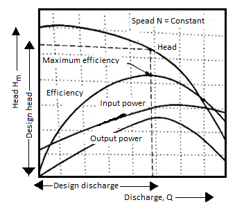
A centrifugal pump is designed to develop certain manometric head and discharge at constant speed since the pumps are usually driven by A.C. Motors. In certain cases, the pumps may be driven by an I.C. Engine at variable speed or the pump in actual practice may needed to develop a certain head or discharge. Under these actual conditions, the behaviour of the pump will be different than expected. Therefore, various tests on the pump under variable conditions are conducted in order to predict the behaviour and performance of the pump. The test results are then plotted on a graph under different flow rates, head and speed.
The curves thus obtained are known as characteristic curves for the pump.
Types of Performance Characteristic Curves
The performance characteristic curves are broadly divided into following four categories:
1. Main characteristic curves.
2. Operating characteristic curves.
3. Iso-efficiency or Muschel curves.
4. Constant head and constant discharge curves.
- Main Characteristic Curves
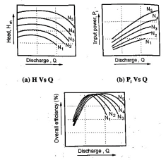
Main characteristic curves are obtained by test run at constant speed and the discharge is varied by means of delivery valve.
At each discharge, the manometric head Hm and input power P are measured and the overall efficiency ηo is calculated. Test curves are plotted between Hm vs Q, P vs Q and ηo Vs Q as shown in figure for that constant speed. The test run is repeated by running the pump at another constant speed. A family of curves will be obtained a various constant speed N1, N2 .... As shown in Fig.
2. Operating characteristic curves
The pumps are designed for maximum, efficiency at a given speed called designed speed. Therefore, the pumps are test run at designed speed as provided by the manufacturer of the pump. The discharge is varied as discussed in case of main characteristic curve and the head and power input are measured. The overall efficiency of the pump is calculated. The performance curve thus obtained at design speed are called operating characteristic curve at shown in figure.
3. Iso-efficiency or Muschel curves
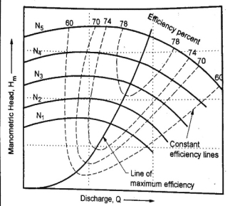
Iso-efficiency i.e. constant efficiency curves are useful in predicting the performance on entire operations and its best performance.
These characteristic curves can be drawn with the help of ηo Vs Q and Hm vs Q curves shown in figure in previous part. The method is as follows:
- Draw a horizontal line on ηo Vs Q curve. It represents the constant efficiency line.
- The points at which the constant efficiency line cuts the constant speed lines, the discharges are noted.
- At a given discharge and speed, the Hm is noted from Hm vs Q graph.
- These values of Hm and Q at constant efficiency and speed are projected on a graph of Hm vs Q as shown below.
- The points corresponding to same overall efficiency are joined with smooth curve. These curves represent the iso efficiency curves.
4. Constant head and constant discharge curves
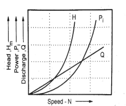
Pumps do not always operate at designed speed and conditions. So, it is necessary to compute performance of pump under various conditions to predict the performance. For these curves, delivery valve opening is fixed and kept constant during the test on pump. Then it is operated at variable speed and characteristics are plotted as shown below.
Definition
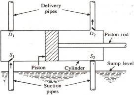
The Reciprocating Pump is a Positive Displacement type pump that works on the basis of piston movement in forward and backward directions. When a specified amount of fluid (usually sump) needs to be carried from the lowest to the highest location by applying pressure, reciprocating pumps are used. It is used in various industries including Gas industries, Petrochemical industries, Oil refineries
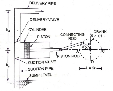
Diagram
Parts
- Water Sump
It's where the water comes from. Water is to be delivered from the sump to the delivery pipes through the piston .It is source
- Strainer
It functions as a mesh, allowing all dirt, dust particles, and other debris to be filtered out of the sump. If there is no strainer, debris or dust will enter the cylinder, clogging the area and interfering with the pump's operation.
- Suction Pipe
The suction pipe's primary function is to gather water from the sump and transport it to the cylinder via a suction valve. The water sump and the cylinder are connected via the suction pipe.
- Suction Valve
It's a non-return valve, which means it can take fluid from the suction pipe and send it to the cylinder, but not the other way around. The flow is unidirectional in this sense. This valve only opens at time of fluid suction and closes when fluid is discharged to the outside.
- Cylinder
It is a cast iron or steel alloy hollow cylinder with a piston and piston rod assembly.
- Piston and Piston rod
The piston rotates backwards inside the cylinder for suction and forwards for fluid discharge. The piston rod allows the piston to move in a straight line, either forward or backward.
- Crank and Connecting rod
The crank is connected to a power source, such as an engine or a motor, for rotation, while the connecting rod functions as a link between the crank and the piston for the conversion of rotational action to linear motion.
- Delivery valve
A delivery valve, like the suction valve, is a non-return valve. The delivery valve closes during suction because the suction valve is open, and the suction valve closes and the delivery valve opens to transfer the fluid during discharge.
- Delivery pipe
The delivery pipe's job is to transport water from the cylinder to the intended place.
Working
The reciprocating pump's crank rotates through an electric motor when voltage is provided. The movement of the piston inside the cylinder is controlled by the angle created by the crank. When the crank reaches position A, i.e.=0, the piston advances to the extreme left of the cylinder, as shown in the diagram. Similarly, when the crank reaches position C, i.e. 180, the piston advances to the extreme right of the cylinder. When the piston is moved to the right extreme position (=0 to=180), a partial vacuum is created in the cylinder, allowing the liquid to enter the suction pipe. This is due to the reason that the sump liquid is subjected to atmospheric pressure, which is much lower than the pressure inside the cylinder. As a result of the pressure difference, water enters the cylinder through a non-return valve. The water that remains in the cylinder volume must be discharged to the discharge pipe via the discharge valve, which can be done when the crank rotates from C to A, i.e. (=180 to=360), moving the piston forward. The pressure inside the cylinder rises due to the forward movement of the piston, which is larger than the ambient pressure. The delivery valve opens and the suction valve closes as a result of this. The water cannot return to the cylinder once it enters the delivery valve since it is a non-return valve. It then enters the delivery pipe, where it is delivered to the desired location.
CLASSIFICATION OF RECIPROCATION PUMP
Based on Cylinder type:
- Single Acting
- Double Acting
The pump is called a single acting pump if the water only comes into contact with one side of the piston, and a double acting pump if the water comes into contact with both sides of the piston.
Based on No. Of Cylinder
- Single Cylinder
- Double Cylinder
- Multi-Cylinder
A single cylinder pump is a reciprocating pump with only one cylinder. It could be a single-action or a double-action pump. Multi-cylinder pumps are those that have more than one cylinder. Two pumps, three pumps, three throw pumps
WORK DONE BY RECIPROCATING PUMP
A single acting pump has only one suction stroke and one delivery stroke each revolution of the crank. The liquid is only delivered during the delivery stroke. As a result, the liquid provided per second flow rate is
Q =LAN/60
L = stroke length = 2r r = stroke radius
A = Cylinder cross-section
N is the number of rotations per minute of the crank.
Therefore Work Done is,

Hs = suction head, Hd = delivery head

For Double Acting pump it has 2 Delivery pipes so the liquid provided per second flow rate is
Q =2LAN/60
Force on piston on Forward Stroke, F g Hs A g H A
Force on Backward Stroke, F g Hs (A) g A Hd
Total force, F g Hs Hd A


Advantages
- Unlike centrifugal pumps, the reciprocating pump does not require priming.
- It can transfer liquid from the sump to the desired height at high pressure.
Disadvantages
- Because there are so many pieces, the maintenance costs are extremely high.
- This pump has a high initial cost.
- The flow rate is lower.
- Pumping viscous fluids is tough.
Key Takeaway
- It is positive Displacement Pump.
- No priming needed and can be used to transfer liquid to the desired height at high pressure.
- Can be Double or single acting, single cylinder or multi cylinder
- The flow rate is lower and pumping viscous fluids is tough.
- Work Done

Slip of pump is defined as the difference between the theoretical discharge (Qth) and actual discharge (Qact).
Slip = Qth Q act)
Percentage Slip=

Cd = Co-efficient of discharge
Negative Slip: In the majority of cases, the slip is positive. However, in some situations, the actual discharge of the pump may exceed the theoretical discharge, causing Cd to be greater than one and the slip to be negative, resulting in negative slip. This happens in pumps with a long suction pipe and a small delivery head, especially when they're running fast. This is because the inertia pressure opens before in the suction pipe builds up to the point where the delivery valve the suction stroke is finished. As a result, even before the delivery stroke begins, some liquid is pumped right into the delivery pipe. As a result, the real discharge will be higher than the theoretical discharge.
Key Takeaway
Slip of pump is defined as the difference between the theoretical discharge (Qth) and actual discharge (Qact).
Slip = Qth Q act)
The velocity of the piston does not remain constant during its reciprocating action. At the ends, it's zero, and in the middle, it's maximum.
If the piston motion is supposed to be simple harmonic, this is only true when the connecting rod is quite long in comparison to the crank length.
Angular velocity of crank==2 N t /60
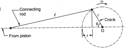
Linear movement is X r r cos r cost
Velocity will be derivative of X that is v= rsin
Acceleration is derivative of velocity that comes out as = r2cos
By theory of Continuity,
Velocity of liquid in suction × area of suction pipe = Velocity of piston Vp × area of piston Ap
Vs x As = Vp x Ap

Acceleration

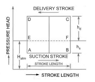
Theoretical Indicator diagram
It's a graph that shows the pressure head on the piston plotted along the vertical ordinate and the stroke length (swept volume is proportional to stroke length) displayed along the abscissa for one complete crank turn.
EF = atmospheric pressure head
AB = pressure head in the cylinder during suction, less than Hatm by hs
CD= pressure head in the cylinder during deliver, more than Hatm by hd
Work input to drive the pump 
Mass of the liquid influenced by acceleration =density multiplied by volume, 
Force is mass X acceleration 
Pressure =Force/ area

Pressure head= Pressure/specific weight
On suction side

On Delivery side

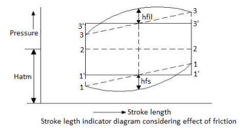
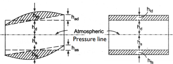
During the suction stroke, the pressure head inside the cylinder will not be equal to hs, as it was in the ideal indicator diagram, but it will be equal to the sum of hs and has. Because has is positive at the start of the suction stroke, the total pressure head in the cylinder will be hs +has less than the atmospheric pressure head.
ϴ is 90 in the middle of the suction stroke, so has=0, and the pressure head in the cylinder will be hs lower than the atmospheric head. The pressure head in the cylinder will be hs – has below the atmospheric pressure head at the conclusion of the suction ϴ is 180 stroke and has is negative, so the pressure head in the cylinder will be hs – has below the atmospheric pressure head. For suction stroke; the indicator diagram will be show by 1A1, also the area of 1A1 = Area of 1’A1’
Similarly, the indicator diagram for the delivery stroke can be designed so that had is positive at the start of the delivery stroke and thus the pressure head in the cylinder is higher than the ambient pressure head. The pressure head in the cylinder will be hd + had
had = 0 in the middle of the delivery stroke, therefore the pressure head in the cylinder is equal to hd above ambient pressure head. Had is (-)ve at the end of the delivery stroke, therefore the pressure in the cylinder will be higher than the ambient pressure head. The pressure head in the cylinder will be hd – had
For delivery stroke; the indicator diagram will be show by 3B3, also the area of 3B3 = Area of 3’B3’
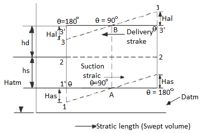
The indicator diagram for 1’-1’-3’-3’ has been changed to 1-1-3-3 due to acceleration in the suction and delivery pipe. However, because the area of the indication diagram is the same, the pump’s work remains the same.
The indication diagram can be tweaked further to account for friction losses in the suction and delivery pipes. The equation for head loss due to friction in a pipe can be found here. The head loss due to friction hfs and hfd will be equal to zero at the start and conclusion of each stroke. The head loss due to friction hfs will be greatest when theta is 90 degrees in the middle of the stroke. The maximum values of hs and hfd are calculated as follows:


The updated indicator diagram, which takes into account the effects of friction and piston acceleration, is shown below.
Key Takeaway
- Indicator Diagram is a graph that shows the pressure head on the piston plotted along the vertical ordinate and the stroke length (swept volume is proportional to stroke length) displayed along the abscissa for one complete crank turn
- The Effect of acceleration Shifts the Diagram but the area remains constant and hence the work done. The Effect of Acceleration is given by

When  and
and 
When  and
and 
When  and
and 
- The friction has parabolic relation and hence parabolic curves are seen on diagram
An air vessel is a closed cast iron chamber with a bottom hole that connects to a suction or delivery pipe. Compressed air is contained in the vessel's upper part.
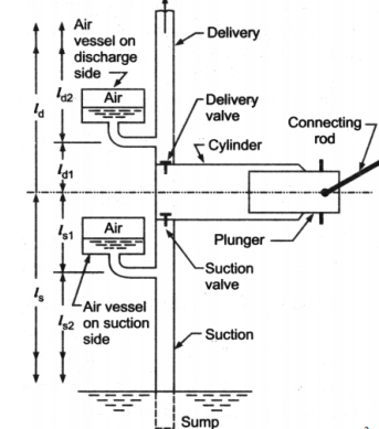
A reciprocating pump's air vessel functions similarly to an I.C. Engine's fly wheel. The compressed air at the top of the vessel can contract and expand to absorb the majority of the pressure variations. When the pressure rises, water over the mean discharge is driven into the air vessel, compressing the air inside. When the water pressure in the pipe drops, the compressed air ejects the excess water out, implying that the air vessel works as an intermediary reservoir on the suction side, accumulating water first before being delivered to the pump's cylinder. Water is sent to the air vessel first, then to the delivery pipe. The water in the pipe is constantly flowing.
Work Done by Air Vessel
In single Acting Cylinder mean Discharge from pump

Instantaneous Flow rate

Net discharge

If the equation is positive, liquid is flowing into the air vessel; if the equation is negative, liquid is flowing out of the air vessel; and if there is no liquid flowing into or out of the air vessel, the equation equals zero. The relation is parabolic


This results in two valves of ϴ =18 degrees or 161 degrees
The discharge is equivalent to mean discharge for these crank angle positions.
In double acting Pump instantaneous Discharge

Mean Discharge from pump

Net Discharge


The oscillations in the velocity of flow in suction and delivery pipes are reduced by using air vessels, which reduces head frictional losses in the pipes and saves a certain amount of energy. It is expected that the air vessel is installed relatively close to the pump cylinder, and that head loss due to friction in the tiny pipe between the pump and the air vessel is minimal. Because the flow velocity in the pipe beyond the air vessel is uniform and equal to the mean velocity, the power lost in friction per second is equal to

Power lost in friction per stroke when there is no air vessel

Power saved by fitting air vessel

The percentage of the power saved by air vessel installation
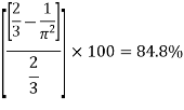
For a double-acting pump, the discharge is 2 times and lost in power per stroke is

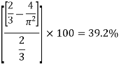
The percentage of the power saved by air vessel installation
Advantages of Air vessel
- Reduce the probability of suction pipe separation.
- The suction pipe length below the air vessel can be extended.
- Pump has the ability to run at a higher pace.
- Constant rate of flow on the delivery side.
- A significant quantity of energy can be saved in the supply of an accelerating head.
Key Takeaway
- A reciprocating pump's air vessel functions similarly to an I.C. Engine's fly wheel. The compressed air at the top of the vessel can contract and expand to absorb the majority of the pressure variations.
- The percentage of the power saved by air vessel installation 84.8% for single acting pump and 39.2 in case of Double acting Pump
The following table summarizes the capabilities of centrifugal and positive displacement pumps.
Property | Centrifugal | Positive Displacement |
Effective viscosity range | Efficiency decreases with increasing viscosity (max. 200 centipoise) | Efficiency increases with increasing viscosity |
Pressure tolerance | Flow varies with changing pressure | Flow insensitive to changing pressure |
Efficiency decreases at both higher and lower pressures | Efficiency increases with increasing pressure | |
Priming | Required | Not required |
Flow (at constant pressure) | Constant | Pulsing |
Shearing (separation of emulsions, slurries, biological fluids, food stuffs) | High speed motor damages shear-sensitive mediums | Low internal velocity. Ideal for pumping shear sensitive fluids |
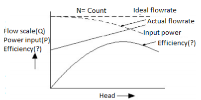
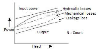
Curves are created by graphing discharge, power input, and overall efficiency against the head developed by the pump at a constant speed. The flow rate of a reciprocating pump working at constant speed is independent of the head created by the pump under ideal conditions, but in fact, the flow rate of a reciprocating reciprocating pump gradually decreases as the head developed by the pump increases. With an increase in the head created by the pump, the input power for a reciprocating pump grows almost linearly beyond a certain minimal amount. The overall efficiency of a reciprocating pump improves as the head is increased. These losses are made up of mechanical losses and Leakage losses Hydraulic losses, which persist even when the pump works at constant speed and the supply discharges at a regular rate under variable heads. Mechanical and leakage losses both increase as the head on the pump increases, although remaining essentially same.
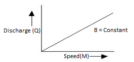
The reciprocating pumps may be required to run at a varied speed on occasion.
References:
1. Introduction to fluid mechanics and Fluid machines by S.K Som, Gautam Biswas, S Chakraborty.
2. Fluid mechanics and machines by R.K Bansal.
3. F. M. White, Fluid Mechanics, 6th Ed., Tata McGraw-Hill, 2008.
4. Fluid Mechanics and Its Applications by V.K.Gupta et.al.
5. Fluid Mechanics by YunusCengel.