Unit – 5
Refrigeration Cycles
The Reversed Carnot Cycle:
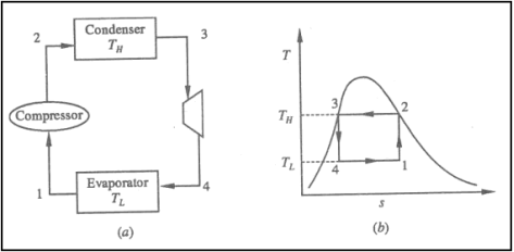
The reversed Carnot cycle is an excellent refrigeration cycle where external heat sources and heat sinks are kept at a constant temperature. The diagram below depicts a reversed Carnot refrigeration system with a gas as the working fluid, as well as the cycle diagram on T-s and P-v coordinates. The cycle, as depicted, is made up of the four processes listed below:
Process 1-2: Reversible, adiabatic compression in a compressor
Process 2-3: Reversible, isothermal heat rejection in a compressor
Process 3-4: Reversible, adiabatic expansion in a turbine
Process 4-1: Reversible, isothermal heat absorption in a turbine
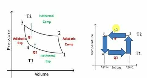
In process 1-2: There is no heat flow into or out of the refrigerator because the gas is isentropically compressed.
In process 2-3: Isothermally (T2=T3), heat is expelled into the sink (e.g., outside air). The amount of heat ejected per unit mass of gas is represented as
QC=T2 (S2−S3).
In process 3-4: The gas expands isentropically. P4 and T4 are the pressure and temperature. At this point, heat transfer is nil.
In process 4-1: The gas expands isothermally (T4=T1), absorbing heat from its surroundings (e.g., room). This is where the cooling occurs. The amount of heat extracted from the source per unit mass of gas is referred to as
QH=T1(S1−S4) =T1(S2−S3)
The work done during the process is simply
W=QH−QC
= T1(S2−S3) - T2 (S2−S3).
= (T1−T2) (S2−S3)
The reverse Carnot cycle's efficiency is defined as the amount of heat removed from the cold reservoir divided by the amount of work input:
ηcool=QC / W
ηcool= T2 (S2−S3) / (T1−T2) (S2−S3)
So ηcool = T2 / T1−T2
Coefficient of Performance (COP)
The performance of refrigerators is expressed in terms of coefficient of performance (COP):
Coefficient of performance of the system working on the Reverse Carnot cycle
C.O.P = Heat absorbed / work done
= qa /qa – qr
= T1(S1 – S3)/ (T2 – T1) (S1 – S3 )
= T1/ T2 – T1
Although the reverse Carnot cycle is the most efficient between fixed temperature limits, no refrigerator could be built using this cycle. This is because the isentropic process necessitates high speed, whereas the isothermal process necessitates extremely low speed.
The reversed Carnot cycle is the most efficient refrigeration cycle that operates between two temperatures. It establishes the highest theoretical COP.
Key Takeaways:
1) C.O.P = Heat absorbed / work done
2) The efficiency of the reverse Carnot cycle is the heat removed from the cold reservoir / the amount of work input
The amount of heat removed from an object to be cooled by a refrigerating machine per unit time. The capacity of a refrigerator is measured in watts or kilocalories per hour. It is determined by the power of the refrigerating machinery, the temperature conditions under which it operates, and the refrigerant used. The refrigerating capacity of a vapor-compression machine is primarily determined by the volumetric capacity of the refrigerating compressor and the amount of heat required to evaporate 1 kg of refrigerant per unit time in a specific thermodynamic cycle and at a specified refrigerant boiling point and condensation temperature.
Each refrigerant has its own capacity for heat transfer. The greater its capacity, the more heat it transfers when moving at a constant rate.
Divide the output of the heat pump in British Thermal Units (BTUs) by 2,930. If it moves 150,000 BTUs per hour, the formula is 150,000 / 2,930 = 51.2 kilowatts.
Divide the amount of refrigerant moved by the time it takes the heat pump to move it. If it can pump 3.6 kg of refrigerant in 10 seconds: 0.36 kilogrammes per second = 3.6 / 10
Subtract the answer to step 1 from the answer to step 2: 51.2 kilojoules / 0.36 = 142.2 kilojoules per kilogramme.
Ton refrigeration, or simply tonne, is the standard unit of refrigeration, denoted by TR. It is the rate of heat transfer required to produce one tonne (2000 lbs) of ice at 32°F from 32°F water in one day, i.e., 24 hours. In British thermal units, the enthalpy of solidification of water from and at 32 F is 144 Btu/lb.

In general, 1 TR equates to 200 BTUs of heat removal per minute. Thus, if a refrigeration system can cool at a rate of 400 Btu/min, it is a two-ton machine. A machine rated at 20 tonnes can cool at a rate of 20 *200 = 4000 Btu/min. This refrigeration unit is currently in use in the United States, the United Kingdom, and India. The standard MKS unit of kcal/hr is used in many countries.


When the Btu tonne unit is expressed in SI units, the result is 210 kJ/min or 3.5 kW. The refrigeration effect is a term used in refrigeration to describe the amount of cooling produced by a system. This cooling comes at the expense of some type of energy. As a result, a term known as coefficient of performance (COP) is commonly defined as the ratio of refrigeration effect to energy input. n the MKS it can be seen that:
When the Btu tonne unit is expressed in SI units, the result is 210 kJ/min or 3.5 kW.
The refrigeration effect is a key term in refrigeration that describes the amount of cooling produced by a system. This cooling is obtained at the expense of some form of energy. As a result, it is common practise to define a term known as coefficient of performance (COP) as the ratio of refrigeration effect to energy input.
Both the refrigeration effect and the energy input should be calculated in the same unit when calculating COP.

Key Takeaway:
Tonne unit is expressed in SI units, the result is 210 kJ/min or 3.5 kW.
Air cycle refrigeration systems use compressed and expanded air as a refrigerant, compressing and expanding it to generate heating and cooling capacity.
Why use air cycle?
• The working fluid (air) is free, environmentally friendly, safe, and non-toxic.
• Air cycle equipment is extremely dependable, lowering maintenance costs and system downtime.
• When operating outside of its design point, the performance of an air cycle unit does not deteriorate as much as that of a vapour-compression unit.
• An air cycle unit can produce heat at a useful temperature while operating in a refrigeration cycle. When combined with cooling, highly efficient, low-energy processes are possible.
• When compared to vapour-compression units, air cycle units can produce a much larger temperature difference between the hot and cold sides. That is to say:
For near-cryogenic processes, very cold air can be produced.
Heat at a useful temperature can be produced, which, when combined with cooling, can result in highly efficient, low-energy processes.
Working of Air Cycle:
The reverse Brayton or Joule cycle (Bell-Coleman cycle) is used in air cycle refrigeration. Heat is removed from compressed air before it is expanded to a lower temperature than before it was compressed. Work must be extracted from the air during expansion, or the entropy will increase. An expansion turbine extracts work from the air by removing energy as the expanding air drives the blades around.
This work can be used to power other devices such as generators or fans. However, it is frequently used to power a directly connected (bootstrap) compressor, which raises the compressed (hot) side pressure without additional external energy input, essentially recycling the energy removed from the expanding air to compress the high-pressure air even further.
The increase in pressure on the hot side raises the temperature even higher, causing the air cycle system to produce more usable heat (at a higher temperature). The cold air after the turbine can be used as a refrigerant either directly in an open system or indirectly in a closed system via a heat exchanger. The efficiencies of compression and expansion, as well as the heat exchangers used, limit the efficiency of such systems to a large extent.
Slow speed reciprocating compressors and expanders were initially used. The inefficiency and dependability of such machinery were major factors in their replacement with vapour compression equipment. However, the development of rotary compressors and expanders (such as those found in automobile turbochargers) greatly improved the air cycle's isentropic efficiency and reliability. Advances in turbine technology, as well as the development of air bearings and ceramic components, promise even greater efficiency gains.
Reversed Brayton Cycle:
Process 1-2: Reversible, adiabatic compression in a compressor
Process 2-3: Reversible, isobaric heat rejection in a heat exchanger
Process 3-4: Reversible, adiabatic expansion in a turbine
Process 4-1: Reversible, isobaric heat absorption in a heat exchanger
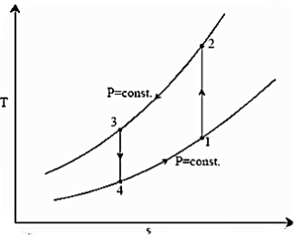
Process 1-2: Gas is compressed entropically from state 1 to state 2 at low pressure. Using the steady-state energy equation and ignoring changes in kinetic and potential energy, we can write:


And 
Where 
Process 2-3: A heat exchanger rejects heat sensibly and isobarically to a heat sink as hot and high-pressure gas flows through it. Due to heat exchange, the enthalpy and temperature of the gas decrease during the process; no work transfer occurs, and the entropy of the gas decreases. Again, applying steady flow energy equation and second T ds equation:


Process 3-4: The high-pressure gas from the heat exchanger flows through a turbine, where it undergoes isentropic expansion and delivers network output. The temperature of the gas decreases from T 3 to T 4 during the process. From steady flow energy equation:


And 
Where  pressure ratio
Process 4-1: Cold and low-pressure gas from the turbine flows through the low temperature heat exchanger, sensibly and isobarically extracting heat from a heat source and providing a useful refrigeration effect. Due to heat exchange, the enthalpy and temperature of the gas rise during the process, no work is transferred, and the entropy of the gas increases. Again, applying steady flow energy equation and second T ds equation:


From the above equations, it can be easily shown that

Applying 1st law of thermodynamics to the entire cycle:

The COP of the reverse Brayton cycle is given by:

Using the relation between temperature and pressures, the COP can also be written as:

For fixed heat rejection temperature (T3) and fixed refrigeration temperature (T1), the COP of reverse Brayton cycle is always lower than the COP of reverse Carnot cycle (Figure), that is

Bell-Coleman cycle works on Reverse Brayton cycle:
The refrigerant in an air refrigeration system is air, which is always in the gaseous phase. Because the heat removed is only sensible heat, the coefficient of performance (C.O.P) is low.
The various process is:
Process 1-2: The air that exits the evaporator is routed through a compressor. Where it is isentropically compressed to higher pressure and temperature.
Process 2-3: This high pressure, high temperature air is then cooled at constant pressure to a low temperature in a cooler.
Process 3-4: This high pressure, low temperature air is then expanded in an expander in an isentropic manner to lower pressure and temperature. The temperature of the air will be the lowest at point 4.
Process 4-1: This low temperature air is then passed through the heater coils, where it absorbs heat from the space to be cooled, specifically the refrigerator, and the air is heated back to the initial temperature while also cooling the refrigerator. And the cycle continues.
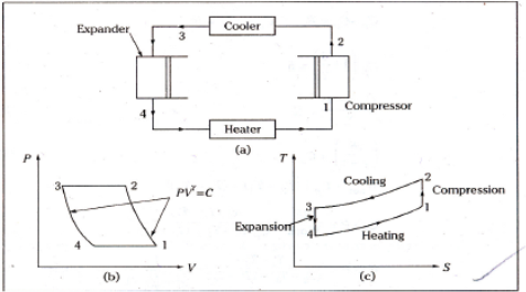
Refrigeration effect=Heat removed from the refrigerator

Work input=
Work input 
Work input 

But 

Process 1-2 is isentropic

Process 3-4 is isentropic

From (2) and (3)


From (4) and (5)

For polytropic process
Net work


Advantages:
- Air is inexpensive and widely available.
- It is not combustible.
Because the weight of an air refrigeration system is less for a given capacity than that of other systems, it is widely used for aircraft cooling.
Disadvantages:
- Because heat removed by air is only sensible heat, the weight of air required is large.
- The system's C.O.P is low in comparison to other systems.
Key Takeaway:

For polytropic process
Net work


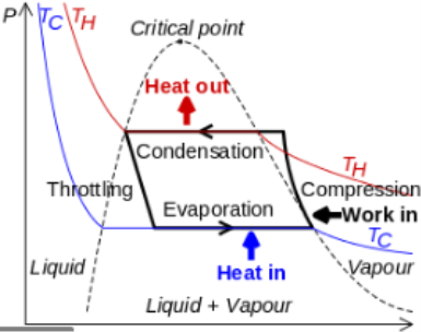
One of the many refrigeration cycles and the most widely used method for air-conditioning buildings and automobiles is vapor-compression refrigeration or vapor-compression refrigeration system (VCRS), in which the refrigerant undergoes phase changes.
Vapor-compression cycle refrigeration is a process that transfers heat from a relatively cold source to a hot medium by utilising the physics of phase change heat transfer and the unique properties of a refrigerant. Simply put, refrigeration systems move heat efficiently from a cold source to a hot heat sink (normally air). The compressor, condenser, expansion valve, and evaporator are the basic components of a refrigeration system.
The compressor is the system's beating heart. The compressor compresses a low temperature, low pressure refrigerant vapour into a high temperature, high pressure vapour. This high-temperature, high-pressure vapour then enters the condenser, where heat is removed and transferred to either air or water. The energy stored in the high-pressure gas is released as the heat is removed, and the refrigerant gives up its latent heat as it reverts to a hot liquid.
The hot, high-temperature liquid then exits the condenser and enters the expansion valve, where a pressure drops causes some of the hot gas to vaporise. The temperature of the refrigerant stream is lowered as a result. The refrigerant at the expansion valve's exit is a low temperature two-phase fluid.
This two-phase fluid enters the evaporator and comes into contact with the heat source. Through phase change heat transfer, the heat from the source boils off the refrigerant, and the low temperature, low pressure gas enters the compressor, completing the cycle.
It is beneficial to comprehend the refrigerant cycle in the depicted quadrant. Because of the high pressure, high temperature upper half, the refrigerant can become significantly hotter than ambient air, forcing heat transfer into a normally hot environment.
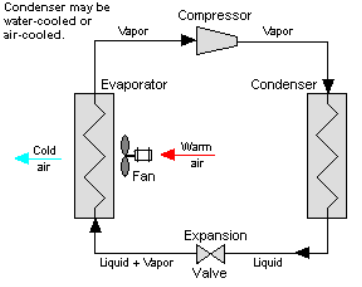
The refrigerant can absorb heat from a source that is not as hot as the environment during the low temperature, low pressure half of the cycle. The compressor works to increase pressure, and the expansion valve ensures that sufficient pressure is maintained in the condenser for heat transfer.
Cooling air, liquids, or cold plates can all be cooled using the vapour compression cycle. All that is required to accomplish this is to modify the evaporator to accommodate the cooled systems. The evaporator serves as a refrigerant to an air heat exchanger in order to create an air-cooling system. The air-cooling system is used to cool air-cooled rack-mounted equipment in buildings, automobiles, and electronics enclosures.
To cool liquid, the evaporator serves as a refrigerant once more, this time to a liquid heat exchanger, with the pumped liquid cooled by the evaporating refrigerant. The liquid cooled system is used for liquid-cooled systems such as lasers, electronics, and medical devices.
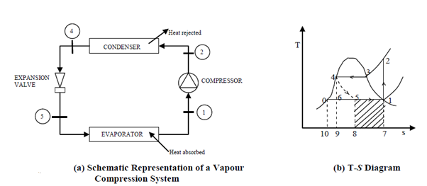
The thermodynamics of the vapour compression cycle can be examined using the temperature versus entropy diagram shown. The circulating refrigerant enters the compressor as a saturated vapour at point 1 in the diagram. The vapour is entropically compressed (compressed at constant entropy) from point 1 to point 2 and exits the compressor as a superheated vapour. The amount of heat added above the boiling point is referred to as superheat.
From point 2 to point 3, the vapour passes through a section of the condenser, which cools the vapour and removes the superheat. Between points 3 and 4, the vapour is condensed into a saturated liquid as it travels through the remainder of the condenser. Condensation takes place at essentially constant pressure.
Between points 4 and 5, the saturated liquid refrigerant passes through the expansion valve and experiences a sudden drop in pressure. A portion of the liquid is adiabatic flash evaporated and auto refrigerated as a result of this process (typically, less than half of the liquid flashes). The process of adiabatic flash evaporation is isenthalpic (occurs at constant enthalpy).
Between points 5 and 1, the cold, partially vaporised refrigerant travels through the coil or tubes in the evaporator, where it is completely vaporised by the warm air (from the space being refrigerated) circulated across the coil or tubes in the evaporator by a fan. The evaporator operates at essentially constant pressure and boils off all available liquid after adding 4–8 kelvins of superheat to the refrigerant to ensure complete evaporation. Because the compressor cannot pump liquid, this serves as a safeguard. To complete the thermodynamic cycle, the resulting refrigerant vapour returns to the compressor inlet at point 1.
The preceding discussion is based on the ideal vapor-compression refrigeration cycle, which does not account for real-world factors such as frictional pressure drop in the system, slight internal irreversibility during refrigerant vapour compression, or non-ideal gas behaviour.
Simple saturated cycle
The vapor-compression refrigeration is the most widely used cycle for refrigerators, air-conditioners, and heat pumps.
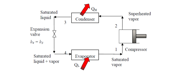
Assumptions for ideal vapor-compression cycle:
• All irreversibility’s in the evaporator, condenser, and compressor are ignored; and there are no frictional pressure drops.
• The refrigerant flows through the two heat exchangers at constant pressure (evaporator and condenser)
• Heat losses to the environment are ignored
• The compression process is isotropic.
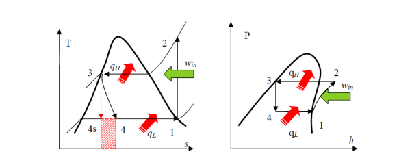
• A reversible, adiabatic (isentropic) compression of the refrigerant. The saturated vapor at state 1 is superheated to state 2.
Wc =h2 − h1
• An internally reversible, constant-pressure heat rejection process in which the working substance is de-superheated and then condensed to a saturated liquid at 3. The working substance rejects the majority of its energy to the condenser cooling water during this process.
QH = h2 − h3
• An irreversible throttling process in which temperature and pressure decrease while maintaining constant enthalpy. At state 4, the refrigerant enters the evaporator as a low-quality saturated mixture.
h3 = h4
• An internal, reversible, constant-pressure heat interaction in which the refrigerant (two-phase mixture) evaporates to a saturated vapour at state point 1. The refrigerated space surrounding the evaporator provides the latent enthalpy required for evaporation. The refrigeration load is the amount of heat transferred to the working fluid in the evaporator.
QL = h1 − h4
Because throttling is an irreversible process, the ideal compression refrigeration cycle is not an internally reversible cycle.
The refrigerant would enter the evaporator at state 4s if the expansion valve (throttling device) was replaced by an isentropic turbine. As a result, the refrigeration capacity (area under 4-4s) would increase while the net work input would decrease (turbine will produce some work). However, due to the added cost and complexity, replacing the expansion valve with a turbine is not feasible.
The COP increases by 2 to 4% for every °C increase in evaporating temperature or decrease in condensing temperature.
Actual vapour compression refrigeration cycle
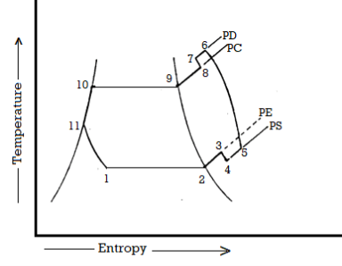
In many ways, the actual vapour compression cycle differs from the theoretical vapour compression cycle, some of which are unavoidable and result in losses. The following are the main differences between the theoretical and actual cycles:
- The vapour refrigerant that exits the evaporator is superheated.
- Refrigeration compression is neither isentropic nor polytropic.
- The condenser sub-cools the liquid refrigerant before it enters the expansion valve.
- The pressure in the evaporator and condenser drops.
The actual vapour compression cycle on T-s diagram is shown. The various processes are discussed below
Process 1-2-3: The flow of refrigerant in the evaporator is depicted in this process. The entry of refrigerant into the evaporator is represented by point 1, and the exit of refrigerant from the evaporator in a superheated state is represented by point 3. Point 3 also represents the entry of superheated refrigerant into the compressor. It is possible that the superheating of vapour refrigerant from point 2 to point 3 is caused by
• Automatic control of the expansion valve so that the superheated vapour of the refrigerant exits the evaporator.
• Obtaining a greater amount of heat from the evaporator via pipes located within the cooled space.
• Heat is picked up from the suction pipe, which connects the evaporator delivery and the compressor suction valve.
The refrigerating effect and compressor work are increased in the first and second cases of superheating the vapour refrigerant. When compared to a saturation cycle at the same suction pressure, the coefficient of performance may be greater, less, or unchanged. Superheating also increases the required displacement of the compressor as well as the load on the compressor and condenser. This is denoted by 2-3 on the T-s diagram.
Process 3-4-5-6-7-8: The flow of refrigerant through the compressor is represented by this process. Because of frictional resistance to flow, when the refrigerant enters the compressor through the suction valve at point 3, the pressure drops to point 4. As a result, the suction pressure (Ps) is less than the evaporator pressure (Pe). The temperature of the cold refrigerant vapour rises to point 5 during suction and prior to compression when it comes into contact with the compressor cylinder walls. 5-6 depicts the actual compression of the refrigerant, which is neither isentropic nor polytropic. This is due to heat transfer between the cylinder walls and the refrigerant vapour.
The temperature of the cylinder walls is somewhere between that of the cold suction vapour refrigerant and that of the hot discharge vapour refrigerant. The heat absorbed by the vapour refrigerant from the cylinder walls during the first part of the compression stroke can be assumed to be equal to the heat rejected by the vapour refrigerant to the cylinder walls. The cooling effect at discharge is similar to the heating effect at suction, as shown in 4-5. At constant pressure, these heating and cooling effects occur. There is a pressure drop due to the frictional resistance of flow, i.e., the actual discharge pressure (Pd) is greater than the condenser pressure (Pc).
Process 8-9-10-11: The flow of refrigerant through the condenser is represented by this process. The cooling of superheated vapour refrigerant to the dry saturated state is represented by process 8-9. The removal of latent heat in process 9-10 converts the dry saturated refrigerant to liquid refrigerant. The sub-cooling of liquid refrigerant in the condenser before passing through the expansion valve is represented by processes 10-11.
This is advantageous because it increases the refrigerating effect per kg of refrigerant flow. It also reduces the volume of refrigerant partially evaporated from liquid refrigerant as it passes through the expansion valve. Large amounts of circulating cooling water at temperatures much lower than condensing temperatures can be used to increase the refrigerating effect.
Process 11-1: Throttling from the condenser pressure to the evaporator pressure represents the expansion of subcooled liquid refrigerant
Effect of Suction Pressure
In the previous article, we discussed how, in practise, the suction pressure (or evaporator pressure) decreases due to the frictional resistance of the refrigerant flow. Consider a hypothetical vapour compression cycle 1'-2'-3-4' in which the suction pressure decreases from ps to ps' as shown on the p-h diagram. It should be noted that the decrease in suction pressure is significant.
- Decreases the refrigerating effect from (h1 - h4) to (h1'- h4') and
- Increases the work required for compression from (h2 – h1) to (h2' – h1')
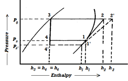
Because the C.O.P. Of the system is the ratio of refrigerating effect to work done, lowering the suction pressure has the net effect of lowering the C.O.P. Of the refrigerating system for the same amount of refrigerant flow. As a result of the decrease in suction pressure, the system's refrigerating capacity decreases, and the refrigeration cost increases.
Effect of Discharge Pressure
We have already discussed how, in practise, the discharge pressure (or condenser pressure) rises due to the frictional resistance of the refrigerant flow. Consider a theoretical vapour compression cycle 1-2'-3'-4' in which the discharge pressure rises from Pd to Pd' as shown on the p-h diagram
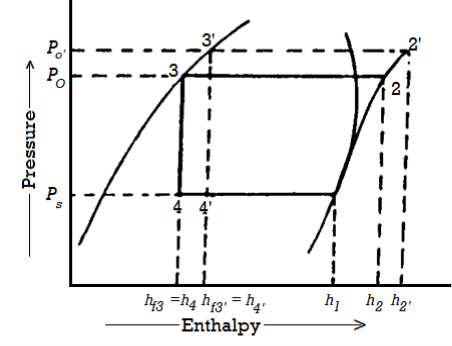
It may be noted that the increase in discharge pressure:
- Decreases the refrigerating effect from (h1 - h4) to (h1 - h4')
- Increases the work required for compression from (h2-h1) to (h2' - h1)
From above, we can see that an increase in discharge pressure has the same effect as a decrease in suction pressure. However, an increase in discharge pressure has a less severe effect on the system's refrigerating capacity than a decrease in suction pressure.
Ideal Reversed Brayton Cycle
Process 1-2: Reversible, adiabatic compression in a compressor
Process 2-3: Reversible, isobaric heat rejection in a heat exchanger
Process 3-4: Reversible, adiabatic expansion in a turbine
Process 4-1: Reversible, isobaric heat absorption in a heat exchanger
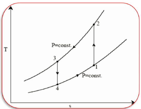


And 
Where 
Process 2-3: Hot and high-pressure gas flows through a heat exchanger and rejects heat sensibly and isobarically to a heat sink. The enthalpy and temperature of the gas drop during the process due to heat exchange, no work transfer takes place and the entropy of the gas decreases. Again, applying steady flow energy equation and second T ds equation:


Process 3-4: High pressure gas from the heat exchanger flows through a turbine, undergoes isentropic expansion and delivers net work output. The temperature of the gas drops during the process from T 3 to T 4. From steady flow energy equation:


And 
Where  pressure ratio
Process 4-1: Cold and low-pressure gas from turbine flows through the low temperature heat exchanger and extracts heat sensibly and isobarically from a heat source, providing a useful refrigeration effect. The enthalpy and temperature of the gas rise during the process due to heat exchange, no work transfer takes place and the entropy of the gas increases. Again, applying steady flow energy equation and second T ds equation:


From the above equations, it can be easily shown that

Applying 1st law of thermodynamics to the entire cycle:

The COP of the reverse Brayton cycle is given by:

Using the relation between temperature and pressures, the COP can also be written as:

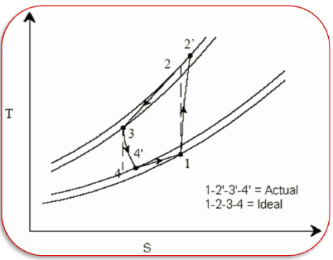
Actual Reversed Brayton Cycle
The actual reverse Brayton cycle differs from the ideal cycle due to
i) Non-isentropic compression and expansion processes
Ii) Pressure drops in cold and hot heat exchangers


Vapour compression refrigeration system
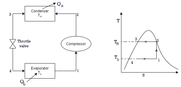
• 1-2: Isentropic compression from state 1 (wet vapour) to state 2 (saturated vapour)
• 2-3: Heat rejection (QH) in the condenser
• 3-4: Isentropic expansion from state 3 (saturated liquid)
• 4-1: Heat absorption (QL) in the evaporator
The COP of the refrigerator



Vapour absorption refrigeration system


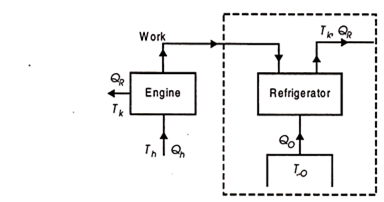
To get the maximum COP, we have to consider the carnot reversed engine.

Similarly we consider the engine as a Carnot engine and


And 
COP of the cycle


This is maximum when  is maximum which is the Carnot thermal efficiency

Note here that this maximum C.O.P is not to be compared COP of vapour compression system which is 

In this case
 Temperature of the source should be as high as possible(source temperature)
 Sink temperature which should be as possible
 Refrigerator temperature which should be as possible
Key Takeaway:

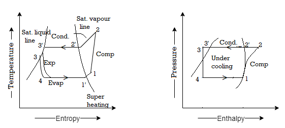
Effect of superheating: As shown in figures a and b, the effect of superheating is to increase the refrigerating effect, but this increase in the refrigerating effect comes at the expense of an increase in the amount of work required to achieve the upper pressure limit. Because the increase in work is greater than the increase in refrigerating effect, the overall effect of superheating is a low value of C.O.P.
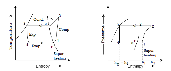
Sub-cooling has the effect of cooling the liquid refrigerant below the condensing temperature for a given pressure. The process of sub-cooling is depicted in the figure by 2'-3'. The effect of sub-cooling, as shown in the figure, is to increase the refrigerating effect. Thus, sub-cooling increases C.O.P if no additional energy is expended to obtain the extra cold coolant required.


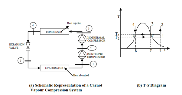
The COP of a Carnot vapour compression cycle is given by


Effect of evaporator pressure
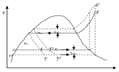
As illustrated in the figure, a decrease in evaporator pressure p1 causes states 5 and 1 to shift to states 5 and 1, respectively. As a result, the compressor's work input increases by areas 0 -1 -1-0 and 1-1 -2 -2. As a result, the COP and capacity of the refrigeration system decrease.
Effect of Condenser pressure
Under the process 5-5, the refrigeration effect is reduced by an area on the T-S diagram. Simultaneously, the condenser work increases by an area of 2-2"-4'-4 when compared to the normal cycle. As a result, when compared to the ideal cycle, the COP and refrigeration Systems effect are reduced. Furthermore, the work input has increased, but it is slightly less than the increase caused by a change in evaporator pressure.
b and c on the p – h diagrams clearly show the effects of reduced evaporator pressure and increased condenser pressure.
Refrigerants and their properties
A refrigerant is a working fluid used in the refrigeration cycle of air conditioning systems and heat pumps where in most cases they undergo a repeated phase transition from a liquid to a gas and back again.
The most common refrigerant includes Chlorofluorocarbons (CFCs), Hydrochlorofluorocarbons (HCFCs), Hydrofluorocarbons (HFCs), and Natural Refrigerants. Freons or halocarbons are synthetically produced. The classification also depends on their chemical elements chlorine (Cl), hydrogen (H), carbon (C), and Florine (F)
Physical Properties of Refrigerants
- Low Freezing Point. Refrigerants should have low freezing point than the normal operating conditions.
- Low Condensing Pressure.
- High Evaporator Pressure.
- High Critical Pressure.
- High Vapor Density.
- High Dielectric strength. .
- High Latent Heat of Vaporization.
- High Heat Transfer Coefficient.
Refrigerant’s classification
In the refrigeration industry, refrigerants are currently identified by numbers. The American Society of Heating, Refrigeration, and Air Conditioning Engineers (ASHRAE) has standardised the numbering system for refrigerants in common use.
Refrigeration R-11 R-12 R-22 R-717 R114(R40) R-500 R502
R-764 | Name and Chemical Formula Trichloromonofluoromethane  Dichlorodifluoromethane  Monochlorodichlorodifluoromethane  Ammonia  Azeotropic mixture of 73.9% (R-22) and 26.2% R-152a Azeotropic mixture of 48.8% (R-22) and 51.2% R-115 Sulphur Dioxide  |
Because refrigeration is a heat removal process, a medium for heat transfer is required. A refrigerant is a medium of heat transfer that absorbs heat by evaporating at low temperatures and gives up heat by condensing at high temperatures and pressure.
In its broadest sense, the term refrigerant also refers to cooling mediums such as cold water, brine solution, and antifreezes. As a result, the refrigerant can be divided into two types: primary refrigerants and secondary refrigerants.
Primary refrigerants, as commonly defined, are only those working mediums that actually go through the cycle of evaporation, compression, condensation, and liquefaction, such as NH3, CO2, SO2, Freon group, and so on.
Secondary refrigerants are those working mediums that transfer heat from a remote location to the refrigeration system's evaporator. Cooling mediums such as ice and solid CO2 are thus secondary refrigerants rather than primary refrigerants. Secondary refrigerants' desirable properties include specific gravity, freezing point, thermal conductivity, viscosity, and specific heat.
I. Halocarbon Compounds:
This group is a chemical compound formed from the base methane CH4 and ethane C2H6 and includes refrigerants which contain one or more of the three halogens i.e., Chlorine, Fluorine and Bromide.
These refrigerants are:
F-11 Trichloromonefuoro methane CCl3F
F-12 Dichlorodifluoro methane CCl2F2
F-22 Monochlorodifuloro methane CHClF2
F-114 Dichlorotetrafluoro ethane CClF2CCIF2
II. Azeotropes:
This group consist of mixtures of refrigerants which do not separate into their compounds with pressure or temperature changes and have fixed thermodynamic properties, e.g., F-500(F-12-.73.8% + F-152, 26.2%).
III. Hydrocarbons:
This group contains organic compounds, and many hydrocarbons are used as refrigerant in industrial installations. They are highly flammable but possess satisfactory thermodynamic properties.
Examples are- CH4 (methane), C2H6 (ethane) etc.
IV. Inorganic Compound:
These refrigerants are:
711 Ammonia NH3
718 Water H2O
729 Air
744 Carbon dioxide CO2
764 Sulphur dioxides SO2
V. Oxygen Compounds:
This group contains oxygen element e.g., ethyl-ether C2H5OC2H6.
VI. Nitrogen Compounds:
This group contains nitrogen element e.g., methylamine CH3NH2.
VII. Unsaturated Organic Compounds:
This group is mainly hydrocarbon group of base ethylene C2H4 and propylene C3H6. There are thus number of refrigerants commercially available and are sold under different trade names.
Vapour absorption system:
High grade energy, i.e., electric power, is used in the vapour compression system to run the compressor motor. Heat, on the other hand, is directly used as a source of energy in absorption refrigeration systems. Of course, using heat as such may be preferable because it avoids the various energy transformations required in the generation of electrical energy from heat energy.
It may be remembered that the vapour was compressed in the compression system by undergoing a large change in volume during the compression process. As a result, a large portion of the power was consumed in the process. If there were a way to increase the pressure of the refrigerant without changing its volume significantly, the work requirements would be drastically reduced (by about 95 percent or so).
This could be accomplished by dissolving the refrigerant in an absorbent and supplying heat to the solution for compression purposes. The absorption cycle accomplishes this goal by introducing the refrigerant into solution prior to the compression process and removing it from the solution immediately following the process. Raoul's law governs the absorption of vapour.
The primary distinction between vapour compression and vapour absorption cycles will thus be the replacement of the compressor in the vapour compression cycle by a set of equipment that achieves the above-mentioned goal. The other critical component, namely the condenser, expansion device, and evaporator, will be present in both systems.
Simple Vapour Absorption Cycle:
Illustrates the simplest scheme of equipment required for the replacement of the compressor.
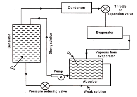
Equipment replacing the compressor (simple vapour absorption system of refrigeration)
QA = Heat added or supplied
QR = Heat rejected to cooling
The fundamental distinction between vapour compression and vapour absorption Water as an absorbent and ammonia as a refrigerant are the most commonly used fluids in an absorption system. The evaporator vapour is allowed to mix and be absorbed in the absorber. The heat of absorption generated during the process is rejected from the absorber to the circulating cold water via a heat exchanger dipped in the absorber's solution.
The absorber's strong aqua-ammonia solution is pumped up to condenser pressure and fed to the generator, which is the system's main energy consumer. The generator receives heat. Because the boiling point of the refrigerant NH3 is lower than that of the absorbing liquid H2O, the vapours emitted by the generator are primarily those of the refrigerant.
These vapours are then routed to the condenser. The liquid refrigerant from the condenser then travels to the evaporator via an expansion valve or throttle valve, where it absorbs heat from the substances or bodies to be refrigerated. After that, the liquid refrigerant evaporates, and the vapours enter the absorber, completing the cycle.
The weak aqua-ammonia solution left in the generator as a result of refrigerant vapour separation is drained back to the absorber to repeat the cycle.
Because the weak aqua-ammonia solution leaving the generator is under high pressure, and the pressure in the absorber is less than the generator or condenser pressure, a pressure reducing valve is installed in the weak solution line to the absorber. The system's energy requirements are higher at the generator and pump than at the compressor in the vapour compression system. Because the volume of liquid handled by the pump is so small, the power required here is negligible in comparison to that required by the generator.
References:
1. Basic and Applied Thermodynamics by PK Nag, MCGRAW HILL INDIA.
2. Thermodynamics for Engineers by Kroos& Potter, Cengage Learning.
3. Thermodynamics by Shavit and Gutfinger, CRC Press.
4. Thermodynamics- An Engineering Approach by Cengel, MCGRAW HILL INDIA.
5. Basic Engineering Thermodynamics, Joel, Pearson.