Unit-2
Vapour power cycle
Rankine Cycle:
The Rankine cycle is the major working pattern of all force plants where a working liquid is constantly evaporated and condensed.
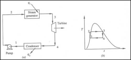
Fig 1
•1-2 Isentropic Pressure:
The squeezing element of the condensate is raised in the feed siphon. Considering the low unequivocal volume of fluid, the siphon work is moderately little and regularly excused in thermodynamic estimations.
• 2-3 Isobaric Heat Transfer
High-pressure fluid enters the heater from the feed siphon (1-2) and is warmed to the immersion temperature (2). Further extension of energy causes dissipation of the fluid until it is totally changed over to immersed steam (3)
• 3-4 Isentropic Expansions:
The vapour is extended in the turbine, in this way making work which may be changed over to power. in practice the extension is limited by the temperature of the cooling medium and by the disintegration of the turbine cutting edges by liquid entrainment in the fume stream as the cycle moves further into the two-stage district. Leave fume attributes should be more noteworthy than 90%.
The vapour liquid mixtureleaving the turbine (3-4) is condensed at low pressure generally in a surface condenser utilizing cooling water. In very much planned and looked after condensers, the pressing factor of the vapour is well below atmospheric pressing, moving toward the immersion pressing factor of the working liquid at the cooling water temperature.
Energy added in steam generator: q1= h3 – h2
Energy rejected in the condenser, q2 =h4 – h1

Reheating of Steam:
In the warm cycle, the extension of steam from the initial state 1 to the condenser pressure is completed in at least two or more stages relying on the quantity of reheat utilized.
Cycle efficiency: improves with reheat, anyway the cycle productivity in a solitary warm plant is affected by pressure at which steam is warmed. The efficiency increment as the reheat pressing factor is brought down and arrives at a top at a pressing factor proportion somewhere in the range of 0.20 and 0.25.
Warming steam likewise increment the organization yield of turbine
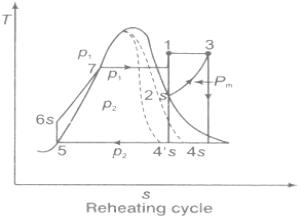
Fig 2

Reheating steam also increase the network output of turbine.
Advantages of Re‑heating:
1) Due to reheating, network done increments.
2) Heat supply increments.
3) Thermal effectiveness tangle increment or diminishing relying on the mean temperature of warmth expansion.
4) Due to reheating, the turbine exit dryness fraction increases so moisture decreases ‑ so blade erosion becomes minimum ‑ so life of the turbine will be increased.
Regeneration:
(i).The mean temperature of heat addition (thus proficiency) can likewise be expanded by reducing the amount of heat added at low temperatures in the economizer part of steam generator.
(ii) In the recovery cycle energy is exchanged inside between the extending fluid in the turbine and the compressed liquid before heat expansion.
(iii).Ideal regenerative cycle does not influence work output from turbine, it is more productive with high steam rate.
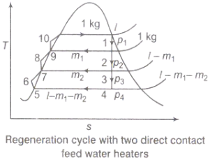
Fig 3
Efficiency of Steam Power Plant: Overall efficiency of the steam per plant is given by


Combined Cycle Power Generation:
It is a gathering of heat engine that works with a comparative wellspring of heat. The standard of consolidated cycle power generation is that the exhaust of one heat engine is utilized as the source of heat for another heat engine. This process increases the overall efficiency of a heat engine.

Advantages of Regeneration cycle:
Characteristics of Ideal Working Fluid
1) The fluid ought to have high critical temperature and the saturation pressure at the temperature of heat rejection ought to be over the climatic pressing factor.
2) Specific heat of fluid ought to be little.
3) The saturated vapour line of T-s outline near the turbine extension measure.
4) The freezing point of the fluid should be below the room temperature
5) The liquid ought to be synthetically steady, non-poisonous, non-destructive, not exorbitantly viscous and low in expense.
Superheating the steam to a high temperature
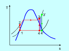
Fig 4 the effect of Superheating the Steam to a Higher Temperature
The impact of superheating the steam to a high temperature on the Rankine cycle proficiency is outlined on a T-s graph on the left. By superheating the stream to a high temperature (from state 3 to state 3'), the normal steam temperature during heat expansion can be increased. The blue zone is the net work expanded due to superheating the steam to a high temperature.
Key Points:
1) Internal irreversibility of Rankine cycle (Genuine cycle) is brought about by fluid frictions throttling and mixing.
2) Externally, irreversibility of the Rankine cycle is caused because of the temperature distinction between the burning gases and the working liquid on a similar side and the temperature contrast between the consolidating working liquid and the condenser cooling water on the sink side.
3) Due to reheating, the turbine exit dryness fraction increases so moisture decreases ‑ so blade erosion becomes minimum ‑ so life of the turbine will be increased.
The strategy for exergy analysis focuses on the quantitative assessment of the exergy misfortunes (irreversibilities) related with a framework. Consequently, it is needed to compute the irreversibility in all the parts of the power cycle for the estimation of exergy efficiency. The irreversibility or exergy misfortune in every one of the segments is determined for the predetermined dead state (P0, T0).
Boiler:
The mass flow rate of steam (ms) needed to be created in the boiler to deliver a output of 500MW power can be acquired from the energy balance as given below:
ms = 500×1ooo kW/Wnet kg/s (1)
Using this, the mass of the flue gas (mg) required to obtain the required mass flow rate of steam can be found by the energy balance equation i.e.,
Heat gained by the steam = Heat lost by the flue gas
ms (h1 − h4) = mg (hA − hB)
mg = ms (h1−h4)/(hA−hB) (2)
Exergy or Accessibility at state point 1
E1 = ms (h1 − T0s1) kW (3)
Exergy or Accessibility at state point 4
E4 = ms (h4− T0s4) kW (4)
Irreversibility in the boiler is,
IBOILER = (EA− EB) − (E1− E4) kW (5)
Substituting the E1, E4 from Eq. (3) & (4)
IBOILER = mg (EA− EB) – ms [(h1− h4) − T0 (s1− s4)] kW (6)
Steam Turbine:
The irreversibility in the steam turbine is given by
ITURBINE = T0 ms (s2− s1) kW (7)
Condenser:
Mass flow rate of cooling water circulated to condense ms,
Kg /s of steam is obtained from the energy balance is
mcwcpw(Twi − Two) = ms(h2− h3)
mcw = ms (h2−h3)/cpw(Twi−Two) (8)
Irreversibility in the condenser,
ICONDENSER = T0[ms(s2− s3) − (mcwcpwln (Two/Twi)]kW (9)
Exhaust:
Irreversibility of the exhaust,
IEXHAUST = EB (10)
Pump:
Irreversibility rate in the boiler feed pump,
IPUMP = msT0(s2− s1)kW (11)
Total Irreversibility:
Total Irreversibility is,
ITOTAL = [IBOILER + ITURBINE + ICONDENSER + IEXHAUST + IPUMP]kW (12)
Fractional Exergy loss:
The meaning of the fractional exergy loss of the segment is the ratio of irreversibility of the individual part to the total irreversibility of the cycle. Its worth is assessed for all the parts of the cycle. It gives the data with respect to the deficiency of valuable energy in all parts for various working factors. The fractional exergy misfortune equations of every segment are as per the following,
Fractional exergy loss in the boiler is IBOILER/ ⅀I × 100 (13)
Fractional exergy loss in the turbine is
ITURBINE/ ⅀I × 100 (14)
Fractional exergy loss in the condenser is,
ICONDENSER / ⅀I × 100 (15)
Fractional exergy loss in the Pump is,
IPUMP/⅀I × 100 (16)
Fractional exergy loss in the exhaust is,
IEXHAUST / ⅀I × 100 (17)
Steam power plants are as yet the foundation of the total power generation in the Asia pacific. Hence even a little improvement through expanding the effectiveness tremendously affects the fuel saving and furthermore decrease in discharge of ozone harming substances. Hence one ought not to pass up a great opportunity any chance to discover the available resources to build the effectiveness of the steam power cycle. The ideal behind any improvement or adjustment is to increase the thermal efficiency of the power plant. Consequently thermal efficiency improvement procedures are:
Lowering the Condenser Pressure
Steam leaves the turbine and enters the condenser as immersed combination in accordance with the relating pressing factor of steam in the condenser. Bringing down the condenser pressure consistently helps in conveying more net work in the turbine as more extension of steam in turbine is possible.
By the help of T-s graph the impact of bringing down the condenser pressure on the performance of the cycle can be seen and understood.
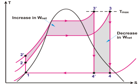
Fig 5-Effect of increasing the boiler pressure
Positive Effects of Lowering the Condenser Pressure
Negative Effects of Lowering the Condenser Pressure
The effect of bringing down the condenser-pressure isn't comes with no results. In this way following are the unfavourable impacts of bringing down the condenser pressure:
Net Effects of Lowering the Condenser Pressure
Super Heating the Steam to Higher Temperature
Superheating of steam is the phenomenon in which heat is transferred to the steam to super heat the steam to higher temperature by maintaining the constant pressure in the boiler.
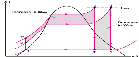
Fig 6
The shaded area in the above T-s diagram clearly showing the increase in net work (3-3’-4’-4)on account of increase in superheat temperature of steam.Additional heat input in the form of energy, leaves the cycle as work i.e increase in work output surpass the additional heat input and heat rejection. Thermal efficiency of the rankine cycle increases on account of increase in steam temperature.
Positive Effects of Increasing the Steam Temperature
One desirable effect of increasing the increasing the steam temperature is that it doesn’t allow to the last stage moisture % of steam to increase. This effect can be easily seen on the T-s diagram (Fig: 6) above.
Negative Effects of Increasing the Steam Temperature
Increasing the steam temperature results in small increase in heat input. There is a limit to which the steam can be superheated and used in the power cycle. These limiting factors are related to metallurgical proveness at high temperature and economic viability.
Presently in supercritical power generating units, steam temperature at turbine inlet is around 620oC. Decision of any further increase in steam temperature can be judiciously taken only after doing the metallurgical due diligence and evaluation of the cost-implications.
Net Effects of Increasing the Steam Temperature
From the T-s diagram (Fig:6) the net effect of temperature increase is more towards positive side, because the gain from the network output surpasses the increase in heat input and slight increase in heat rejection. So it is always beneficial to increase the steam temperature after accessing the reliability and economic viability.
Key points
1) Superheating of steam is the phenomenon in which heat is transferred to the steam to super heat the steam to higher temperature by maintaining the constant pressure in the boiler.
2) it is always beneficial to increase the steam temperature after accessing the reliability and economic viability.
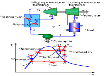
Fig 7 Schematic and T-s Diagram of an Ideal Reheat Rankine Cycle
The above section states that increasing the boiler pressure can increase the thermal efficiency of the Rankine cycle, but it also increases the moisture content at the exit of the turbine to an unacceptable level. To correct this side effect, the simple Rankine cycle is modified with a reheat process. The schematic of an ideal reheat Rankine cycle is shown on the left with its T-s diagram. In this reheat cycle, steam is expanded isentropic ally to an intermediate pressure in a high-pressure turbine (stage I) and sent back to the boiler, where it is reheated at constant pressure to the inlet temperature of the high-pressure turbine. Then the steam is sent to a low-pressure turbine and expands to the condenser pressure (stage II) . The total heat input and total work output is
qin = qprimary + qreheat = (h3 - h2) + (h5 - h4)
wtotal, out = qturb, I + qturb, II = (h3 - h4) + (h5 - h6
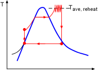
Fig 8)
Multistage Reheat Approaching an Isothermal Process: When the number of the reheat stages increases, the expansion and reheat processes approach an isothermal process at the maximum temperature. But using more than two stages is not practical.
A reheat process is considered for a simple Rankine cycle to reduce the moisture content at the turbine exit. The pressure at which the steam should be reheated and the net work output are to be determined.
Assumptions:
The efficiency (thermal) of a steam power plant is increased by means of heat regeneration like gas-turbine plants. In regenerative cycle, the feed water is preheated by steam taken from some sections of the turbine,before it goes to the steam generator from the condenser. This process of exhausting steam from the turbine at certain point during its expansion and using it for heating the feed water supplied to the boiler is known as“Bleeding.” Due to this process the boiler with hotter water while a small amount of work is lost by the turbine.
Process 1-2: The steam is bled from the turbine and passed on to the heater. Process 1-3, which shows the isentropic expansion of remaining steam in the turbine from pressure p1 to p3.
Process 3-4: At constant pressure p3 and temperature T3, the drain steam from the steam turbine is condensed in the condenser.
Process 4-5: The feed water from condenser is pumped to heater. Process 5-6: Here in this heater (1-ms) kg of steam is heated.
Process 2-6: Here in this heater ms kg of steam is to be condensed. Process 6-7: Water from the heater which is at low pressure is pumped into the boiler with high pressure. Process 7-1: At constant pressure p1 & temperature T1, the water is completely evaporated into steam.
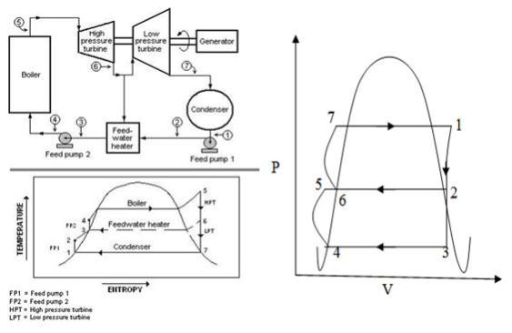
Fig 9) Plant Layout with T-S & P-V diagram of Regenerative Cycle
2.6 Feed water heater
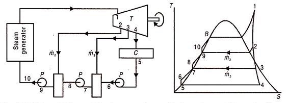
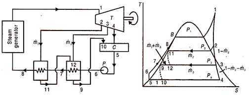
In open or direct contact feed water heater, the extraction steam is mixed directly with incoming sub-cooled feed water; to produce saturated water at extraction steam pressure Fig. 22.3 (a) and (b) shows a ‘schematic flow diagram and corresponding T-s diagram for a Rankine cycle using two such feed water heaters.
Fig 10) Schematic flow and T-S diagram of a non-superheat rankine cycle with two open type feed water heater
Condensate water leaves the condenser at 5 and is pumped to 6 to a pressure equal to that of the extraction steam at 3. The now-subcooled water at 6 and wet steam at 3 mix in the low pressure feed water heater to produce saturated water at 7.
Amount of bled steam m3 should essentially be such that subcooled water at 6, should be raised close to its saturation point. If it were much less, the water will be heated to below its saturation temperature and advantage of feed water heating would be partially lost. If it were more there will be surplus steam at point 7. This would mean loss of turbine work and presence of steam-water mixture at 7 which is difficult to pump.
The pressure at 6-7 should be less than extraction steam pressure at 3 or else reverse flow of condensate water would enter the turbine at 3. The second pump pressurises saturated water at 7 to a subcooled condition at 8, which is at the pressure of extraction steam at 2. In the high pressure feed water heater superheated steam at 2, mixes with subcooled water at 8 to produce saturated water at 9. This is pressurised to 10 by a pump to enter the steam generator at its working pressure.
Steam at 2 or 3 loses its latent heat of vaporisation which is much larger than the gain of sensible heat by water at 8 or 6. Therefore the quantity of extracted steam ṁ2 and ṁ3 is only a small fraction of the steam passing through the turbine.
In addition to a condensate pump, one pump for each open feed water heater is required. This is a disadvantage.
Open feed water heaters because of vigorous action of mixing remove non-condensable gases like Air, O2, H2, CO2 from the feed water. They are therefore known as de-aerating heaters or DA.
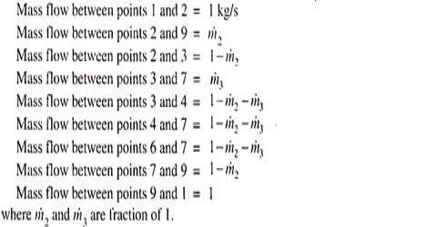
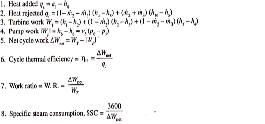
Mass Flow Rates and Energy Balance:
This is done on the basis of unit mass flow rate at the turbine inlet (point 1)
The mass balance therefore is as follows:
For energy balance, consider the low and high pressure feed water heaters. At low pressure feed water heater, heat lost by condensing steam equals heat gained by feed water heater, or,
This is the easiest and most generally utilized sort in force plants. It is a shell and cylinder type heat exchanger. The feed water goes through the cylinders, and the drained steam, on the shell side exchanges its warmth energy to it and condenses. Hence, they resemble surface condensers, working at higher pressing factors than those in the principle condenser. Since feed water doesn't blend in with the steam and goes through the containers of progressive close feed water warmers, just a single condensate siphon is adequate to pressurize the water from condenser to the boiler. In any case, to diminish the pressing factor ascend in one siphon, one condensate siphon before the feed water heater and one feed water pipe after the feed water radiators are utilized. In the event that deareater radiator is utilized, one heater feed pump is consequently needed after the equivalent.
Figure 11 shows a disentangled stream outline and comparing T-s graph of a non-ideal superheat Rankine cycle. There are two feed water healers. One siphon 5-6 pressurizes the condensate, adequate to go through the two feed water radiators and enters the steam generator at 8. The drained steam consolidated at each FWH is taken care of back to the following lower pressure FWH. The condensate from the last fwh is driven back to the principle condenser. One can envision, at that point, a course from high strain to bring down pressing factor warmers. Subsequently the name.
Fig 11 Schematic flow and T-S diagram of a non-ideal superheat rankine cycle with two closed type feed waters with drains cascaded backward
Wet steam seeped at 3 at the pace of ṁ3 enters the low pressing factor FWH and heats the sub cooled water at 6. The temperature of water at 7 is not as much as saturated temperature at 3. This distinction is known as the Terminal Temperature difference (TTD) and is characterized for all closed FWHS.
TTD or TD = saturation temperature of drained steam – exit water temperature
The estimation of TTD for low pressing factor warmers is positive and is of the request for 3°C. For high pressing heater it could be negative and lies among 0 and – 3°C. On the off chance that no information is accessible, temperature at 7 is taken equal to saturation temperature at 3.
The drain from low pressing factor FWH is directed to the main condenser and enters it as two stage blend at 10. The cycle 9 – 10 is throttling process from the pressure corresponding to to 9 and the principle condenser pressure. Because of choking there is some deficiency of accessibility. Additionally enthalpy at 9 and 10 are equivalent, as the cycle is steady enthalpy one.
The high pressing factor FWH gets superheated steam seeped from the turbine at 2 that streams on the shell side at the pace of ṁ2 and warms the water entering the cylinders at 7. The bay steam at 2 is superheated, henceforth temperature at 8 might be higher than immersion temperature of that steam and TTD might be negative. The channel at 11 might be somewhat subcooled; and is choked to the low pressing factor fwh which it enters at 12 as a two stage blend. There it gets together with the steam seeped at 3 and helps the warming of water in low pressing factor FWH. The channel from low pressing factor fwh is along these lines ṁ2 + ṁ3, which is choked to the primary condenser at 10. The higher pressing factor leave water at 8 is directed to the steam.
Mass Flow Rate and Energy Balance:
A mass balance based on unit flow rate at turbine inlet point 1, is given clockwise by –
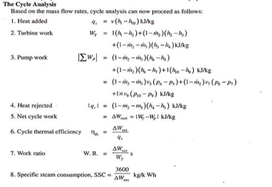
All the relevant pressure and the enthalpy of the eqn are knows. Since there are only two unknown m2 and m3 the equation can be solved.
From mass flow rates, energy balance equations and enthalpy values, we can determine the amounts of steam extracted i.e., ṁ2 and ṁ3, and then the pertinent cycle parameters. We assume mass flow rate of 1 kg/s at turbine inlet (point 1).
This is a second closed type FWH. It avoids throttling and the irreversibilities therein but has to use a small additional pump. Like previous closed type FWH, it is also a shell and tube type heat exchanger. The feed water passes through the tubes the steam passes over them; transfers heat and condenses. They do not mix and only one pump is sufficient to carry water from the condenser to the boiler. If, however, DA is used one more pump would be necessary.
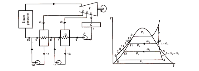
The drain from these FWHS is pumped forward into the main feed water line. Figure shows a simplified flow diagram and corresponding T-s diagram for a non-ideal superheat Rankine cycle with two such FWHS. Like open FWH these heaters also require an additional pump per heater. But the pump is small and carriesonly fractional flows corresponding to ṁ2 and ṁ3 while pumps in open FWH carry full steam and water flow.
Operation:
The drain of low pressure FWH at 13 is pumped forward to the main feed water line and enters it at 14. It mixes with exit water from l.p. heater at 7 and forms mixture at 8. Point 8 is closer to 7 than 1.4 on the T-S diagram because flow at 7 is much greater than the drain flow ṁ3.
Fig 12 Schematic flow and T-S diagram of non-ideal superheat rankine cycle with two closed type feed water heaters with drains pumped forward
The water at 8 enters h.p. heater and is heated to 9. The drain leaves the heater at 11, is pumped to 12. It mixes with the feed water at 9 to form full feed water flow at 10, which crow goes to boiler.
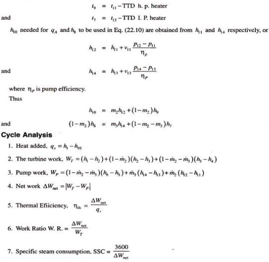
Mass Balance and Energy Balance:
A mass balance based on a mass flow rate of 1 kg/s at turbine inlet (point 1) is given clockwise on T-S diagram by –
The values of h9 and h7 are obtained from the temperature t9 and t7 are equal to the saturated temperature of the steam at each heater minus its terminal temperature difference or
Key points
1) TTD or TD = saturation temperature of bled steam – exit water temperature.
2) The value of TTD for low pressure heaters is positive and is of the order of 3°C. For high pressure heaters it may be negative and lies between 0 and – 3°C
2.7 Binary Vapour Cycle
Generally water is used a working fluid in vapour power cycle as it is discovered to be superior to some other liquid, yet it is a long way from being the ideal one. The binary cycle is an attempt to overcome a portion of the shortcomings of water and to move toward the ideal working liquid by utilizing two liquids. The main attractive qualities of the working liquid appropriate for vapour cycles are:
a. high basic temperature and a protected most extreme pressing factor.
b. Low-triple point temperature
c. Condenser pressure isn't excessively low.
d. high enthalpy of vaporization
e. High thermal conductivity
f. It should be promptly accessible, modest, inert and non-harmful.
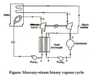
Figure 13: Mercury-steam binary vapour cycle
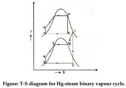
Fig 14
Therefore it can be concluded that no single working fluids may have desirable requirements of working fluid. Different working fluids may have different attractive feature in them, but not all. In such cases two vapour cycles operating on two different working fluids are put together, one is high temperature region and the other in low temperature region and the arrangement is called binary vapour cycle.
The layout of mercury-steam binary vapour cycle is shown in figure. Along with the depiction of T-S diagram figure. Since mercury having high critical temperature (898oC) and low critical pressure (180 bar) which makes a suitable working fluid will act as high temperature cycle (toppling cycle) and steam cycle will act as low temperature cycle.
Here mercury vapour are generated in mercury boiler and sent for expansion in mercury turbine and expanded fluid leaves turbine to condenser. In condenser, the water is used for extracting heat from the mercury so as to condensate it. The amount water entering mercury condenser. The mercury condenser also act as steam boiler for super heating of heat liberated during condensation of mercury is too large to evaporate the water entering of seam an auxiliary boiler may be employed or superheating may be realized in the mercury boiler itself. From the cycle,
Since pump works are very small, it may be neglected. Work from Mercury Turbine, WHg =mg (ha -hb)
Work from Steam Turbine, Wsteam = msteam (h1 -h2)
Pump work, Wpump = mHg (hd -hc)+msteam (h4 -h3)
Heat supplied to the cycle, Qin =mHg (ha -hd)+msteam [(h1 -h6)+(h5 -h4)]
Heat rejected= Qout =mstream(h2-h3)
Efficiency of binary vapour cycle η =W net /Qin
Net work done =W net= Heat supplied =Qin =mHg (ha -hd) +msteam [(h1 -h6)+(h5 -h4 )]
The proceeded with mission for higher warm efficiencies has brought about rather inventive alterations to traditional force plants. The parallel fume cycle examined later is one such alteration. A more well-known alteration includes a gas power cycle besting a fume power cycle, which is known as the joined gas–fume cycle, or simply the consolidated cycle. The joined pattern of most noteworthy interest is the gas-turbine (Brayton) cycle beating a steam turbine
Rankine cycle which has a higher warm effectiveness than both of the cycles executed exclusively Gas-turbine cycles normally work at impressively higher temperatures than steam cycles. The greatest liquid temperature at the turbine bay is about 620°C (1150°F) for current steam power plants, yet over 1425°C (2600°F) for gas-turbine power plants. It is over 1500°C at the burner exit of turbojet motors. The utilization of higher temperatures in gas turbines is made conceivable by on-going improvements in cooling the turbine cutting edges and covering the edges with high-temperature-safe materials, for example, earthenware production. In view of the higher normal temperature at which warmth is provided, gas-turbine cycles have a more prominent potential for higher warm efficiencies. Notwithstanding, the gas-turbine cycles have one inalienable hindrance: The gas leaves the gas turbine at high temperatures (as a rule above 500°C) which deletes any possible increases in the warm productivity. The circumstance can be improved to some degree by utilizing recovery, yet the improvement is restricted. It bodes well to exploit the entirely attractive qualities of the gas-turbine cycle at high temperatures and to utilize the high temperature fumes gases as the fuel hotspot for the lining cycle, for example, a steam power cycle. The outcome is a joined gas–steam cycle, as appeared
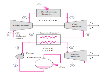
Fig 15 Combined gas–steam power plant
In this cycle, energy is recovered from the exhaust gases by transferring it to the steam in a heat exchanger that serves as the boiler. In general, more than one gas turbine is needed to supply sufficient heat to the steam. Also, the steam cycle may involve regeneration as well as reheating. Energy for the reheating process can be supplied by burning some additional fuel in the oxygen-rich exhaust gases. Recent developments in gas-turbine technology have made the combined gas–steam cycle economically very attractive. The combined cycle increases the efficiency without increasing the initial cost greatly. Consequently, many new power plants operate on combined cycles, and many more existing steam- or gas-turbine plants are being converted to combined-cycle power plants. Thermal efficiencies well over 40 percent are reported as a result of conversion.
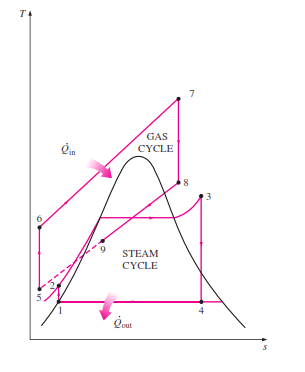
Fig 16
Cogeneration or Combined Heat and Power (CHP) is the sequential generation of two dissimilar forms of useful energy from a single primary energy source, typically mechanical energy and thermal energy. Mechanical energy may be used either, to drive an alternator for generating electricity, or rotating equipment such as motor, compressor, pump or fan for delivering a variety of services. Thermal energy may be used either for direct process applications or for indirectly generating steam, hot water and hot air for dryer or chilled water for process cooling. This cycle provides a wide range of technologies for application in various domains of economic activities. Overall efficiency of energy use in cogeneration mode can be up to 85% and above in some cases. Process 1-2: The steam is continuously taken out from the turbine and passed on to the process heater.
Process 1-3, which shows the isentropic expansion of remaining steam in the turbine from pressure p1 to p3.
Process 3-4: At constant pressure p3 and temperature T3, the drain steam from the steam turbine is condensed in the condenser.
Process 4-5: Water from the hot-well or the surge tank which is at low pressure is pumped into the boiler at high pressure. Here the pumping process 4-5 is isentropic.
Process 2-6: Steam which could have been a waste is used as a process heat to produce electricity.
Process 6-7: Water from the process heater which is at low pressure is pumped into the boiler at high pressure.
Process 8-1: Here the water is totally evaporated into steam and this steam goes into the turbine.
Figure 
Fig 17 Plant Layout with P-V diagram of Cogeneration Cycle
Combustion is a chemical reaction between fuel and oxygen which proceeds at a fast rate with the release of energy in the form of heat. In the combustion of methane e.g.
CH4+2O2(Reactant) = CO2 + 2H2O(products)
One mole of methane reacts with two mole of oxygen to form 1 mole of carbon dioxide and 2 moles of water. The water may be in liquid or vapour phase depending on the temperature and pressure of the products of combustion. Only the initial and final products are being considered without any concern for the intermediate products that usually occurs in a reaction.
Atmospheric air contains 21% oxygen 78% nitrogen and 1% argon by volume. In combustion calculation, however the argon is usually neglected and air is assumed to consists of 21% oxygen79% nitrogen by volume. On mass basis system air contains 23% oxygen and 77% nitrogen.
For each mole of oxygen taking part in a combustion reaction there are 79.0/21.0 = 3.76 moles of nitrogen. So for the combustion of methane the reaction can be written as
CH4+2O2+2(3.76) N2 = CO2+ 2H2O+7.52N2
The minimum amount of air which provides sufficient oxygen for the complete combustion of all the elements like carbon, hydrogen etc. which may oxidize is called the theoretical or stoichiometric air. There is no oxygen in the products when complete combustion is achieved with this theoretical air.in practice however more air than this theoretical amount is required to be supplied for complete combustion. Actual air supplied is usually expressed in terms of percent theoretical air 150% theoretical air means that 1.5 times the theoretical air is supplied thus with 150% theoretical air the methane combustion reaction can be written as
CH4+2(1.5) O2+2(3.76).(1.5)N2 = CO2 + 2H2O + O2 + 11.28N2
Another way of expressing the actual air quality supplied is in terms of excess air. Thus 150% theoretical air means 50% excess air.
While less than theoretical air supply combustion will remain incomplete with some CO present in the product. Even with excess air supply also there may be small amount of CO present, depending on mixing and turbulence during combustion e.g., with 115% theoretical air
CH4+2(1.15) O2+2(1.15)3.76N2= 0.95 CO2+0.05CO+2H2O+0.325O2+8.65N2
By analyzing the product of combustion the actual amount of air supplied in a combustion process can be computed. Such analysis is often given on the dry basis, i.e. the fractional analysis of all the components except water vapour. Following the principle of the conservation of mass of each of the elements it is possible to be making a carbon balance, hydrogen balance, oxygen balance, and nitrogen balance from the combustion reaction equation from which the actual air fuel ratio can be determined.
Key points
1) The minimum amount of air which provides sufficient oxygen for the complete combustion of all the elements like carbon, hydrogen etc. which may oxidize is called the theoretical or stoichiometric air.
2) There is no oxygen in the products when complete combustion is achieved with this theoretical air
The enthalpy of combustion is defined as the difference between the enthalpy of the products and the enthalpy of reactants when complete combustion occurs at a given temperature and pressure.
Therefore

Where hRP is the enthalpy of combustion (kj/kg or kj/kg mol) of the fuel.The values of the enthalpy of combustion of different hydrocarbon fuels at 250c the internal energy of combustion uRP is defined in a similar way.

If all the gaseous constituents are considered ideal gases and the volume of liquid and solid considered is assumed to be negligible compared to gaseous volume

In the case of a constant pressure or steady flow process the negative of the enthalpy of combustion is frequently called the heating value at constant pressure which represents the heat transferred from the chamber during combustion at constant pressure.
Similarly the negative of the internal energy of combustion is sometimes designated as the heating value at constant volume in the case of combustion because it represents the amount of heat transfer in the constant volume process.
The higher heating value (HHV) or higher calorific value (HCV) is the heat transferred when h2o in the products is in the liquid phase. The lower heating value (LHV) or lower calorific value (LCV) is the heat transferred In the reaction when H2O in the products is in the vapour phase.
Therefore
LHV = HHV – m H2O hfg
Where m H2O is the mass of water formed in the reaction.
Theoretically complete combustion can be obtained when stoichiometric amount of air is used. Stoichiometric amount (also termed theoretical air or air for complete combustion) of air can be calculated by considering the products of combustion obtained on complete combustion. In general any balanced chemical equation (mole input = moles output) can be used to calculate stoichiometric amount of air.
In combustion equations 1 to 4, we note that 1mole of C requires 1 mole of O2 or 4.76 moles of air to give 1 mole of CO2 and 3.76 moles of N2. Similarly 1 mole of H2 requires 1/2 mole of O2 or 2.38 moles of air to give 1 mole H2O and 1.88 mole of N2.
In several other metallurgical processes like roasting (conversion of metal sulphide to oxide, reduction of oxides, oxidation of impurities etc) air or pure oxygen is used. In all these cases it is often required to calculate stoichiometric amount of air. For example consider roasting of sulphide;
ZnS + 1.5O2 = ZnO + SO2 5)
PbS + 1.5O2 = PbO + SO2 or in general 6)
MS + 1.5O2 = MO + SO2 7)
M stands for metal. In all the above equations the amount of air can be easily calculated following the stoichiometry of the reactions.
Let us calculate stoichiometric amount of air for combustion of solid fuel of composition 84%C, 5%H, 5% moisture and 6% ash, per kg of coal. Following the stoichiometry of combustion, the amount of air would be
(6.84/12 + 0.06/2) x 4.76 = 0.452 moles/kg coal
= 10.12m3 (1atm,273 K)/kg coal.
Note 1 kg mole= 22.4 m3 (1atm,273 K).
Excess air = (Actual amount of air-theoretical air /theoretical air) x100
Excess air = (Actual amount of o2-theoretical o2 /theoretical o2) x100
In the above example if actual amount of air is 0.5 moles then
Excess air = (0.5 – 0.452 /0.452) x100 = 10.61%
We can also call‐ that 110.61% theoretical air is used for combustion.
Note: Complete combustion can occur only when amount of air is equal to or greater than stoichiometric air. When excess air is used, POC will contain O2 in addition to CO2, H2O, N2 and SO2
It is important to know how much oxygen or air must be supplied for complete combustion of a given quantity of fuel. This information is required in sizing fans and ducts that supply oxidizer to combustion chambers or burners and for numerous other design purposes. The mass air-fuel ratio, A/F, or oxygen-fuel ratio, O/F, for complete combustion may be determined by calculating the masses of oxidizer and fuel from the appropriate reaction equation.
Let’s return to Equation (1):
CH4 + 2O2 + 2(3.76)N2= CO2 + 2H2O + 2(3.76)N2 (1)
The A/F for methane is [(2) (32) + (2)(3.76)(28)]/(12 + 4) = 17.16 and the O/F is
2(32)/(12 + 4) = 4.
Thus 4 kg of O2 or 17.16 kg of air must be supplied for each kilogram of methane completely consumed. Of course it is possible, within limits, to supply an arbitrary amount of air to a burner to burn the fuel. The terms stoichiometric or theoretical are applied to the situation just described, in which just enough oxidizer is supplied to completely convert the fuel to CO2 and H2O.
Thus the stoichiometric O/F and A/F ratios for methane are 4.0 and 17.16, respectively. If less than the theoretical amount of air is supplied, the products will contain unburned fuel. Regardless of the magnitude of A/F, when fuel unburned remains in the products (including carbon, carbon monoxide, or hydrogen), combustion is said to be incomplete. Because air is virtually free and fuel is expensive, it is usually important to burn all of the fuel by using more air than the theoretical air-fuel ratio indicates is needed. Thus most burners operate with excess air.
The actual air-fuel ratio used in a combustor is frequently stated as a percentage of the theoretical air-fuel ratio
% theoretical air = 100(A/F)actual /(A/F)theoretical (2)
Thus, for methane, 120% of theoretical air implies an actual mass air-fuel ratio of
(120/100)(17.16) = 20.59.
Excess air is defined as the difference between the actual and the theoretical air supplied. Accordingly, the percentage of excess air is
% excess air = 100[(A/F)actual (A/F)theoretical]/(A/F)theoretical (3)
Thus, for methane, 120% of theoretical air implies
% excess air = (100)(20.59 . 17.16)/17.16 = 20%.
Note also that combining Equations (2) and (3) yields the following general result:
% excess air = % theoretical air. 100% (4)
Again, the excess air percentage is 120% - 100% = 20%.
.
The air/fuel parameters just discussed emphasize the amount of air supplied to burn a given amount of fuel relative to the theoretical requirement. An alternate approach considers a given amount of air and indicates the mass of fuel supplied the fuel-air ratio, F/A, which is the inverse of the air-fuel ratio. A measure of how much fuel is actually supplied, called the equivalence ratio, is the ratio of the actual fuel-air ratio to the theoretical fuel-air ratio:
θ (F/A)actual / (F/A)theoretical = (A/F)theoretical / (A/F)actual
= 100/ (% theoretical air)
Thus 100% theoretical air corresponds to an equivalence ratio of 1, and 20% excess air to θ= 100/120 = 0.833. When the equivalence ratio is less than 1, the mixture is called lean; when greater than 1, it is called rich.
This section has dealt with the application of combustion chemistry or stoichiometry applied to methane gas. Other fuels for which a reaction equation such as Equation (1) is available may be treated in a similar way. Before considering more complex combustion problems, it is appropriate to investigate the nature and description of the various types of fossil fuels.
The change in enthalpy of a chemical reaction indicates how much heat is absorbed or released by the system. This is valuable information in chemistry, because the exchange in heat affects the reaction conditions and the surroundings, and that needs to be managed and taken into account – in theory, in the laboratory, in industry or in nature in general.
Chemists often want to compare the changes in enthalpy between different reactions. Since changes in enthalpy depend on both temperature and pressure, we need to control for these 2 confounding variables by using a reference set of temperature and pressure. This set of conditions is called the standard conditions, and it sets the standard temperature at 298 degrees Kelvin and the standard pressure at 1 bar.
The standard enthalpy of reaction (or standard heat of reaction) is the change in enthalpy of a chemical reaction under standard conditions; the actual number of moles is specified by the coefficients of the balanced chemical equation. (Since enthalpy is an extensive property, the same reaction under standard conditions could have different changes in enthalpy with different amounts of the reactants and products. Thus, the number of moles of the reaction must be standardized somehow when defining the standard enthalpy of reaction.) The standard enthalpy of reaction has the symbol ΔHº; the º symbol indicates the standard conditions.
Calculating Heat of Reaction from Heat of Formation
An application of Hess’s law allows us to use standard heats of formation to indirectly calculate the heat of reaction for any reaction that occurs at standard conditions. An enthalpy change that occurs specifically under standard conditions is called the standard enthalpy (or heat) of reaction and is given the symbol. ∆HO the standard heat of reaction can be calculated by using the following equation.
∆HO= ∑ n ∆Hf(products) - ∑ n ∆HOf(reactants)
The symbol Σ is the Greek letter sigma and means “the sum of”. The standard heat of reaction is equal to the sum of all the standard heats of formation of the products minus the sum of all the standard heats of formation of the reactants. The symbol “n” signifies that each heat of formation must first be multiplied by its coefficient in the balanced equation.
Example= Calculate the standard heat of reaction ∆HO for the reaction of nitrogen monoxide gas with oxygen to form nitrogen dioxide gas.
Step 1: List the known quantities and plan the problem
Known: From table of Standard Heats of Formation of Selected Substances. we find the following values
Unknown
∆HO=? KJ
First write the balanced equation for the reaction. Then apply the equation to calculate the standard heat of reaction for the standard heats of formation.
Step 2: Solve
The balanced equation is: 
Applying the equation form the text:
![Delta H^circ&=[2 text{ mol NO}_2 (33.85 text{ kJ/mol})] - [2 text{ mol NO}(90.4 text{ kJ/mol}) + 1 text{ mol O}_2 (0 text{ kJ/mol})] \&=-113 text{ kJ}](https://glossaread-contain.s3.ap-south-1.amazonaws.com/epub/1642990224_5698695.png)
The standard heat of reaction is -113 kJ.
The reaction is exothermic, which makes sense because it is a combustion reaction and combustion reactions always release heat.
SummaryEffect of Temperature on Heat of Reaction
The Effect of Temperature on Heat of Reaction is also known asthe Kirchhoff Equation. The heat change accompanying chemical or physical processes generally depends on the temperature at which the process takes place. This dependence is mathematically expressed in the form of what is known as Kirchhoff equation after G. R. Kirchhoff (1858) who first developed this equation. The equation may easily be derived with the help of the first law of thermodynamics.
Kirchhoff’s Equation is equality expressing the temperature dependence of the thermal quantities linked with a chemical reaction through the difference in heat capacities between the products and reactants. The same reaction, when carried at dissimilar temperatures, the enthalpies of reaction are also different.
Kirchhoff equation relates the heat of reaction with the definite heats of a structure before and after the reaction. Kirchhoff equation is represented as
dQ/dt = C – C’
Where, Q is the heat energy evolved throughout the procedure at temperature‘t’ without modifying in volume and C is the specific heats of the reactants and C’ is the specific heats of products.
Consider the process in which the reactants in state A at temperature T1 are converted into products in state B a temperature T2. Assume that all operations are carried out at constant pressure. The conversion may be carried out in two ways but according to Hess’s law, the total heat change must be the same in both cases.
(1) The reactants in state A at temperature T1 are heated to a temperature T2. The heat absorbed is (∆T) (CP)A. where ∆T = T2 – T1, and (CP)A is the heat capacity of the reactants in the state A. The reaction is now allowed to take place at this temperature and the heat change for the process is (HB – HA)2 = ∆H2
The total heat change for the process = (∆T) (CP)A + ∆H2.
(2) The reactants in state A at temperature T1 are considered to products in state B at the same temperature. The heat cement change = (HB – HA)1 = ∆H1. The temperature of the products is then raised from T1 to T2 and the heat absorbed is (∆T) (CP)B, where (CP)B is the heat capacity of the products.
The total heat change for the process = (∆T) (CP)B + ∆H1.
From Hess’s law,
(∆T) (CP)A + ∆H2 = (∆T) (CP)B + ∆H1
or, ∆H2 – ∆H1 = [(CP)B – (CP)A] x (∆T)
= ∆CP (∆T)
Where, ∆CP = (CP)B – (CP)A
or, [∆H2 – ∆H1] / ∆T = ∆CP
For an infinitesimally small change in temperature, one can write,
[d∆H / dT] = ∆CP … … … … (1)
Similarly, it may be shown that if the process is carried out at constant volume the relationship is;
[d∆U / dT] = ∆C … … … … (2)
The relationships (1) and (2) are different forms of the Kirchhoff equation. The equations are useful for calculating the heat 41 reactions at a given temperature when the value is known at another temperature provided the heat capacities of the reactants and products are also known.
A temperature transform occurs when the temperature is increased or decreased by the flow of heat. This shifts the chemical equilibrium toward the products or reactants, which can be resolute by studying the reaction and deciding whether it is endothermic or exothermic. The equation which indicates Effect of temperature on the heat of reaction is known as Kirchhoff’s equation.
Heat of formation, also called standard heat of formation, enthalpy of formation, or standard enthalpy of formation, the amount of heat absorbed or evolved when one mole of a compound is formed from its constituent elements, each substance being in its normal physical state (gas, liquid, or solid). Usually the conditions at which the compound is formed are taken to be at a temperature of 25 °C (77 °F) and a pressure of 1 atmosphere, in which case the heat of formation can be called the standard heat of formation. The heat of formation of an element is arbitrarily assigned a value of zero. By using Hess’s law of heat summation, one can calculate the heat absorbed or evolved in any chemical reaction by summing the known heats of formation or combustion for the steps in that reaction.
Element = compound
which in terms of the the Enthalpy of formation becomes
ΔHrxn= ΔHf
For example, consider the combustion of carbon:
C(s)+O2(g)⟶CO2(g)C(s)+O2(g)⟶CO2(g)
then
ΔHrxn=ΔHf [CO2 (g)]
The sign convention for ΔHfis the same as for any enthalpy change:
ΔHf<0ΔHf<0 If heat is released when elements combine to form a compound and ΔHf>0ΔHf>0 if heat is absorbed.
The sign convention is the same for all enthalpy changes: negative if heat is released by the system and positive if heat is absorbed by the system.
The standard heat of formation, ΔHfº, of a chemical is the amount of heat absorbed or released from the formation of 1 mole of that chemical at 25 degrees Celsius and 1 bar from its elements in their standard states. An element is in its standard state if it is in its most stable form and physical state (solid, liquid or gas) at 25 degrees Celsius and 1 bar.
For example, the standard heat of formation for carbon dioxide involves oxygen and carbon as the reactants. Oxygen is most stable as O2 gas molecules, whereas carbon is most stable as solid graphite. (Graphite is more stable than diamond under standard conditions.)
To phrase the definition in another way, the standard heat of formation is a special type of standard heat of reaction; the reaction is the formation of 1 mole of a chemical from its elements in their standard states under standard conditions. The standard heat of formation is also called the standard enthalpy of formation (even though it really is a change in enthalpy).
By definition, the formation of an element from itself would yield no change in enthalpy, so the standard heat of reaction for all elements is zero.

For such a process the temperature of the products is called the adiabatic flame temperature which is the maximum temperature achieved for the given reactants. The adiabatic flame temperature can be controlled by the amount of excess air supplied. It is the maximum with a stoichiometric mixture. Since the maximum permissible temperature in a gas turbine is fixed from metallurgical considerations close control of the temperature of the product is achieved by controlling the excess air.
For a given reaction the adiabatic flame temperature is computed by trial and error. The energy of the reactants HR being known, a suitable temperature is chosen for the products so that the energy of the products at that temperature becomes equal to the energy of the reactants.
Reference
1) Engineering thermodynamics P.K nag
2) I.C engineering =m.lmathur
3) https://www.physicsforums.com/attachments/flow-calculations-pdf.20219/
4) https://onlinelibrary.wiley.com/doi/pdf/10.1002/0471743984.vse7245
