Unit-3
Boilers
Classification and working of boilers:
A steam boiler or steam generator is a closed vessel in which water is heated, vaporized and converted into steam at a pressure higher than atmospheric pressure. Boiler is a closed vessel in which heat produced by combustion of fuel is transferred to water for its conversion in to steam at the desired temperature and pressure. According to IBR a boiler is closed pressure vessel with capacity exceeding 25.75 Lits used for IBR a boiler is closed pressure vessel with capacity exceeding 25.75 Litres used for generating steam under pressure it includes all the mountings fitted to such vessels which remains wholly or partly under pressure when steam is shut off.
Working Principle of a Boiler
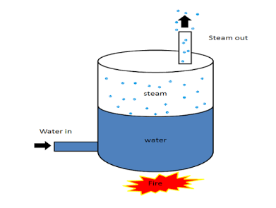
Fig 1 boiler
The boiler works on the same principle as the water is heated in a closed vessel and due to heating, the water changes into steam. This steam possesses high-pressure kinetic energy. The boiler contains water. The water is heated to its boiling temperature by the use of heat from the furnace. Due to the heating of water, it gets converted into high-pressure steam. The steam generated is passed through the steam turbines. As the high-pressure steam strikes the turbine, it rotates the turbine. A generator is attached to the turbine and the generator also starts to rotate with the turbine and produces electricity.
Classifications or Types of Boiler:
There is large number of boiler designs, but they may be classified according to the following ways:
3.1.1 According to the circulation of gases:
Fire Tube Boiler:
As it indicated from the name, the fire tube boiler consists of numbers of tubes through which hot gasses are passed. These hot gas tubes are immersed into water, in a closed vessel. Actually in fire tube boiler one closed vessel or shell contains water, through which hot tubes are passed. These fire tubes or hot gas tubes heated up the water and convert the water into steam and the steam remains in same vessel. As the water and steam both are in same vessel a fire tube boiler cannot produce steam at very high pressure. Generally it can produce maximum 17.5 kg/cm2 and with a capacity of 9 Metric Ton of steam per hour.
(a) Hot gases formed after the combustion of fuel flow through tubes and water surrounds these tubes.
(b) Internally fired.
(c) Working pressure limited to 20 bars.
(d) Steam generation rate is lower.
(e) For a given power, it occupies large floor area.
(f) Not suitable for large power plants.
(g) It carries lot of risk on less working pressure.
(h) Different parts cannot be separated easily, hence it becomes difficult to transport.
(i) Water treatment is not necessary.
(j) Parts are not so accessible for cleaning and inspection.
Fire tube boilers are classified as follows.
l. External furnace:
(i) Horizontal return tubular
(ii) Short fire box
(iii) Compact.
2. Internal furnace:
(i) Horizontal tubular
(a) Short firebox (b) Locomotive (c) Compact (d) Scotch.
(ii) Vertical tubular.
(a) Straight vertical shell, vertical tube
(b) Cochran (vertical shell) horizontal tube.
Advantages of Fire Tube Boiler
Disadvantages of Fire Tube Boiler
Water Tube Boiler:
A water tube boiler is such kind of boiler where the water is heated inside tubes and the hot gasses surround them.
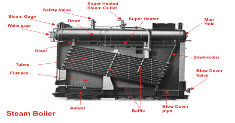
Fig 2 steam boiler
This is the basic definition of water tube boiler. Actually this boiler is just opposite of fire tube boiler where hot gasses are passed through tubes which are surrounded by water.
(a) Water flows inside the tubes and gas surrounds these tubes.
(b) Externally fired.
(c) Working pressure may be as high as 150 bars.
(d) Steam generation rate is higher.
(e) For a given power, it occupies lesser floor area.
(f) Suitable for large power plants
(g) Less risk on explosion due to high working pressure.
(h) Each and every part can be separated easily, so transportation is easier.
(i) In this boiler, water treatment is necessary.
(j) Parts are easily accessible for inspection.
There are many types of water tube boilers, such as
Horizontal Straight Tube Boiler again can be sub-divided into two different types,
Bent Tube Boiler also can be sub divided into four different types,
Advantages of Water Tube Boiler
There are many advantages of water tube boiler due to which these types of boiler are essentially used in large thermal power plant.
Disadvantages of Water Tube Boiler
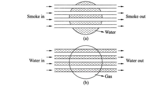
Fig 3 (a) fire tube (b) water tube boilers
3.1.2 According to Circulation of water:
In any water heating vessel heat is transmitted from one place to another not by condition but by convection because water is a bad conductor of heat.Let vessel containing water be heated at its bottom, as the water in the bottom portion is heated therefore its density becomes reduced in comparison to the density of water in the upper portion of the vessel, as a result, the less dense water at the bottom portion of the vessel rise up and comparatively more dense and cold water at the upper portion of the vessel comes down to take its place and thus a convection current is set up in the water until temperature off all water becomes the same.
The method of circulation of water described above is known as free circulation.
In boilers like Lancashire, Babcock, and Wilcox, etc. free circulation of water takes place.
The advantages of free circulation are:
Forced Circulation:
In forced circulation, pumps are used to maintains the continuous flow of water in the boiler. In such a case, the circulation of water takes place due to pressure created by the pump.
The forced circulation system is adopted in more high pressure, high capacity boilers of all of which are water tube type boiler
The advantages of forced circulation are:
3.1.3 According to the number of tubes used:
According to the number of tubes, Boilers may be classified as:
Single tube boiler:
The boiler having only one fire tube or water tube is called single tube boiler.
Example: Cornish boiler
Multi tube boiler
The boiler having two or more fire or water tubes for the circulation of hot gases or water are called multi tube boiler.
Example: Lancashire boiler, Locomotive boiler, Cochran boiler, Babcock and Wilcox boiler etc.
3.1.4 According to the nature of use:
According to nature use, boilers are classified as
Stationary boilers:
For the generation of thermal power and for process work (in chemical, sager and textile industries) boilers used are called stationary boiler.
Locomotive boilers:
Boilers used in locomotive steam engines are called locomotive boilers.
Marine boilers:
Boilers used in steamships are called marine boilers.
3.1.5 According to the nature of the fuels used:
According to the nature of the fuel used boiler may be:
NOTE: Babcock and Wilcox boilers use solid or gaseous fuel.
Volex boilers use oil fuel.
3.1.6 According to the pressure of the boiler:
High-pressure boiler:
The pressure of the boiler above 80 bar.
Medium-pressure boiler:
It has a working pressure of steam from 20 bar to 80 bar. It is used for power generation or process heating.
Low-pressure boiler:
This type of boiler produces steam at 15-20 bar pressure. This is used for process heating.
3.1.7 According to the position of the axis of the boiler shell:
According to the position of the axis of the boiler shell, boilers are classified as:
Vertical boiler:
If the boiler axis is vertical, it is called a vertical boiler. For example, Cochran boiler.
Horizontal boiler:
If the boiler axis is horizontal, it is called a horizontal boiler.
For example, Lancashire boiler.
3.1.8 Stationary boiler and Portable boiler
a) Stationary boilers: The boilers which cannot be transported easily from one place to another are called stationary boilers.
Example: Lancashire boiler, Babcock and Wilcox boiler
(b) Portable boiler: The boilers which can be easily transported (moved) from one place to another are called portable boilers.
Example: Locomotive boiler.
3.1.9 Externally tired and internally tired boilers
(a) Externally fired boiler: - In the boiler if the fire is outside the shell, that boiler is known as externally fired boiler. Example: Babcock & Wilcox boiler
(b) Internally fire boiler:- In the boiler in which the furnace is located inside the boiler shell it is known as internally fired boiler. Example: Cochran boiler, Lancashire boiler etc.
The boiler mountings are fittings which are mounted on the boiler for its proper functioning. Mountings are water level indicator, safety valve, pressure gauge, etc. It may be noted that a boiler cannot function safely without the mountings
Following are the important boiler mountings:
It is an main fitting in the boiler, Water level indicator indicates the water level inside the boiler. It is a safety device upon which safe working of the boiler depends.
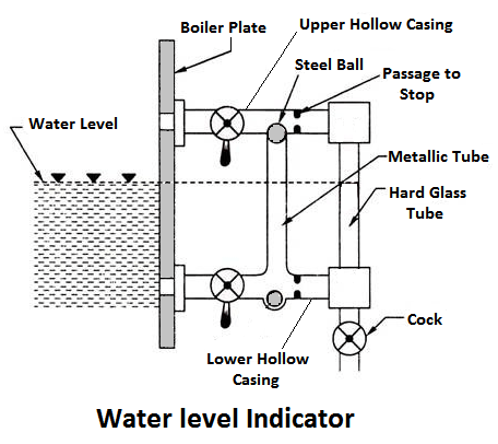
Fig 4
Working PrincipleWater-tube indicator the water consists of a vertical hard glass tube G which is fitted with two gunmetal tubes A and B. The tubes A connect the steam space of the boiler with the glass tube and the tube B connects the water space of the boiler with the glass tube.
The tube A is provided with a valve ‘S’, called a steam valve, and tube B is fitted with another valve ‘W’, called a water valve. In addition to these valves, a third valued, called drain valve, is fitted to the water level indicator through which water together with condensed steam from the gunmetal tube A is drained from time to time.
Pressure gauges are used to measure the pressure of steam inside a steam boiler. The pressure gauge is fixed in front of a steam boiler.
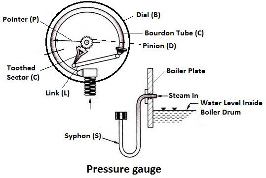
Fig 5
Working PrincipleThe pressure gauge shown in fig is bourdon pressure gauge. It consists of a circular spring tube A. One end of the bourdon tube is closed and connected to a link L and the other end is sequared to a Hollow block B. The link L connects the closed end of the tube to the toothed sector C which is hinged at O. The toothed sector gears with pinion D which carries a pointer P. The pointer moves on a dial graduated in pressure units.
These are the devices attached in the steam boiler for preventing explosions due to excessive internal pressure of steam.
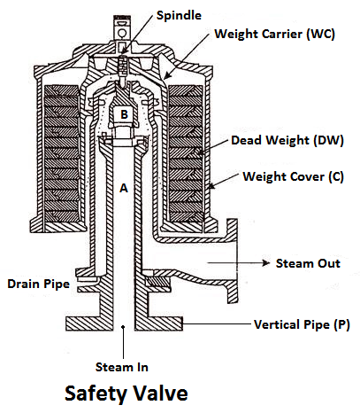
Fig 6
The safety valve is an instrument which prevents the boiler pressure from rising above its normal working pressure by automatically opening when the boiler pressure exceeds the normal working pressure, Thus allowing excess steam to escape into the atmosphere until the pressure comes down to its normal valve. Thus, a safety valve ensures safety to a boiler from being damaged due to excessive steam pressure.
The safety valves commonly used are:The function of a stop valve is to control the flow of the steam from within the boiler and to stop it completely when required. A stop valve or junction valve is used to regulate the flow of steam from the boiler.
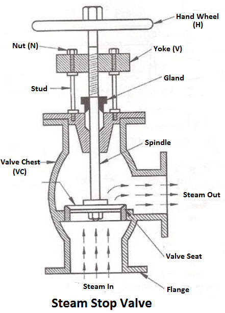
Fig 7
The valves mounted on the boilers, which change the direction of flow of steam by 90° are called junction valves, while valves fitted in pipelines which allowing the steam in the same direction are called stop valve.
The function of a blow-off valve is to remove periodically the sediments deposited at the bottom of the boiler while the boiler is in operation and to empty the boiler while it is being cleaned or inspected.
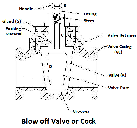
Fig 8
When the blow-off valve is opened the water which is under the pressure of steam, rushes out with tremendous velocity thus carrying out the sediments along with it
When the level of water in the boiler falls, it is brought back to the specified level by supplying the additional water called feed water. The pressure inside the boiler will be high therefore the pressure of the feed water has to be raised by a pump before it is fed into the boiler. The feed water under high pressure is fed into the boiler through the feed check valve.
The function of a feed check valve is to control the flow of water from the feed pump to the boiler and to prevent the backflow of water from the boiler to the pump when the pump pressure is less than the pressure or when the feed pump ceases to work. Evidently feed check valve is placed at the boiler end of the delivery pipe of the feed pump.
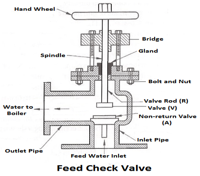
Fig 9
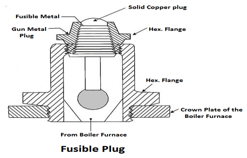
Fig 10
The plug is made up of tin or leads alloy, which has a low melting point. The function of the fusible plug is to put-off the fire in the furnace of the boiler when the water level falls below an unsafe level and thus avoids the explosion, which may take place due to overheating of the tubes and the shell. It is fitted over the crown of the furnace or the combustion chamber.
The boiler accessories are required to improve the efficiency of the steam power plant and to enable for the proper working of the boiler. The boiler accessories are the devices, which form an integral part of a boiler but are not mounted on it. They include superheaters, economiser, feed pump etc. It may be noted the accessories help in controlling and running the boiler efficiently. The boiler accessories aren’t mounted directly on the boiler.
The essential boiler accessories are:
The combustion gases coming out of the boiler contain a large quantity of heat. Therefore the maximum amount of heat from the gases should be recovered before it escapes to the chimney.
In the economiser, heating the feed water does the recovery of heat in the flue gases. The economiser is placed in the path of the gases. They improve the overall efficiency of the boiler by reducing fuel consumption.
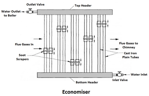
Fig 11
The air preheater is an accessory that recovers the heat in the exhaust gas by heating the air supplied to the furnace of the boiler. Supplying preheated air into the furnace produces a high furnace temperature and accelerates the combustion of the fuel. Thus the thermal efficiency of the plant will be increased.
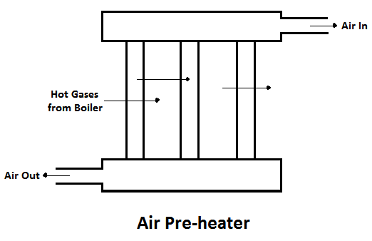
Fig 12
The advantages of air pre-heater are,
The superheaters are used in boilers to increase the temperature of the steam about the saturation temperature.
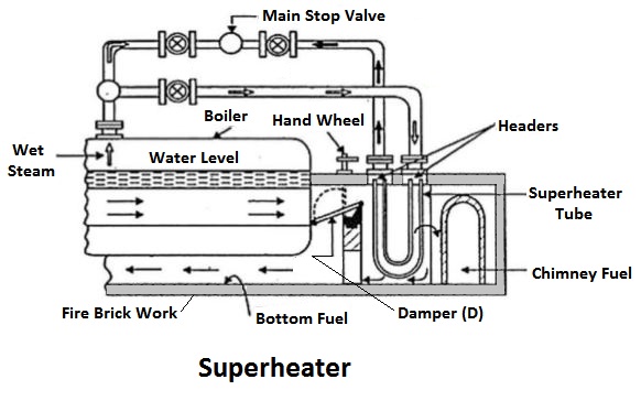
Fig 13
The dry saturated steam generated in the boiler is passed through a set of tubes placed in the path of the flue gases, in which it will be heated further by the hot gas to increase its temperature about the saturation temperature.
A feed pump is a boiler accessory required to force the feed water at high pressure into the boiler. Commonly used pumps are,
The reciprocating pumps are driven directly by coupling them to the steam engine. The rotary pumps are driven by the steam turbines or by electric motors.
Key points
1) Water level indicator indicates the water level inside the boiler. It is a safety device upon which safe working of the boiler depends.
2) The air preheater is an accessory that recovers the heat in the exhaust gas by heating the air supplied to the furnace of the boiler
Draught may be defined as the small pressure difference which causes a flow of gas to take place. In case of a boiler the function of the draught is to force air to the fire and through a boiler furnace and flue, and to discharge the products of combustion to atmosphere via stack or chimney.
Proper combustion in a boiler furnace can only occur when sufficient quantity of air is supplied to the burning fuel. If the supply of air is insufficient, then the combustion will be sluggish and insufficient even with superfine furnace construction and the most skilful stoking.
The classification of draught is as below:
(1) Natural
(2) Artificial.
1) Natural draught
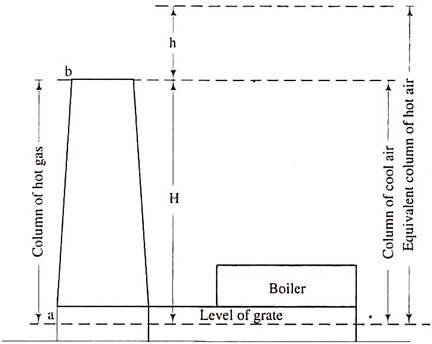
In case of a natural draught if we consider a condition when fire is not lighted, the pressure at the grate level surface is the same at all points on the surface i.e., at the chimney base as well as on the grate and we assume its value to be P1.
Fig 14
The pressure at all points at horizontal surface ‘b’ passing from the top of the chimney in fig. 14 is also the same and we take its value to be P2. The value of P2 is less than P1 because the surface ‘b’ is higher than the surface ‘a’ by H, the height of the chimney. When the fire is lighted up on the grate, the hot gases will fill up the chimney as well as flue gas passages.
Now, though, the pressure at the chimney top is P2 the pressure at the grate level below the grate is P1 but at the base of the chimney it will be P2 + pressure due to the hot gas column of height H. This pressure will be less than P1 because P1 = P2 + the pressure due to the cold air column of height H.
Now, a cold air column of the same height is heavier than a hot gas column and so the pressure difference at the base of the chimney corresponding to grate pressure is the pressure difference in weight of the column of height H of cold air and that of hot gases, and this is known as total static draught or theoretical maximum static draught.
Thus total static draught is the total pressure difference which results owing to the difference in the weights of the column of the hot flue gas inside the chimney and a column of the outside air of the same area and height.
2) Artificial Draught:
In present day boiler installations, the total static draught required varies from 25 to 350 mm of water column because loss in draught takes place in boiler tubes, superheater elements, baffles, economizer and air pre-heater. Besides, resistance to air flow is also offered by combustion equipment.
It will not be practical to build a stack high enough to produce a draught of such a large magnitude. Natural draught is dependent on climatic conditions and is less when the outside air temperature is higher and thus it is necessary to obtain a draught which is independent of weather conditions.
To meet the desired pressure requirement which is independent of climatic conditions, an artificial draught is created. It may be a mechanical draught or a steam jet draught is used while for central power stations and many other boiler installations a mechanical draught is preferred.
Simple and easy method of producing artificial draught is the steam jet draught. It may also be of the forced draught type or induced draught type.
When the jet of steam is directed into the smoke box or in chimney it induces the draught and the air is drawn through ashpit, furl bed and boiler flue tubes. When the jet is installed in the ashpit, the draught becomes of the forced type and air is forced through the fuel bed, boiler flue tubes and the chimney.
In case of locomotives, the exhaust from non-condensing steam engine is directed into the smoke box. With this arrangement the draught is automatically adjusted to suit the requirements of the boiler.
The steam jet draught system requires very little attention and is economical when cheap and plenty of low grade fuels are employed. It has one disadvantage that it cannot be started until steam pressure is available. Steam passing into the furnace will carry away heat in the same manner as moisture in the fuel.
The mechanical draught is the draught created by use of mechanical equipment to create a artificial draught.
The Advantages of Mechanical Draught are:
(i) Increase in Evaporative Power of a Boiler:
By installing the mechanical draught system, the quantity of fuel burnt, per square metre of grate area, is increased. Generally with natural draught system the average fuel consumption per square metre of grate area varies from 80 to 170 kg depending upon the height of the chimney.
With mechanical draught, any type of mechanical stoker can be adopted and any desired rate of fuel consumption upto 200 kg/m2 of grate area can be maintained in any type of boiler. With tubular boilers the fuel can be burnt at a better rate. As the combustion rate of fuel has increased, the steam raising capacity of the plant is increased.
(ii) Capability of Consuming Low Grade Fuel:
With mechanical draught installation many kinds of low grade fuels can be used for steam raising purposes.
(iii) Easy Control of Combustion and Evaporation:
Greater economy in working can be obtained because complete combustion is possible with less excess air. The rate of air supply can be regulated to suit the irate of fuel consumption which in turn regulates the evaporation of steam.
(iv) Prevention of Smoke:
Smoke prevention depends upon the quantity of air supplied and the condition of firing. With mechanical draught and mechanical stokers high temperatures and efficient combustion can be obtained with less difficulty.
(v) Improved Efficiency of the Plant:
As the temperature of flue gases can be lowered with mechanical draught system heat recovery devices are incorporated in the boiler plant. By installing the economizer the temperature of feed water entering boiler is raised, while the air pre-heater heats the combustion air. Both these devices improve the thermal efficiency of the boiler plant.
(vi) Reduction of Chimney Height:
With the mechanical draught system the function of a chimney is only to discharge flue gases t a convenient height to suit the surroundings and comply with local by-laws.
The disadvantages of mechanical draught are:
(ii) Upkeep of machinery
(iii) Increased wear and repairs which are expected owing to the increased duty which the boilers are called upon to perform.
The air preheater is an accessory that recovers the heat in the exhaust gas by heating the air supplied to the furnace of the boiler. Supplying preheated air into the furnace produces a high furnace temperature and accelerates the combustion of the fuel. Thus the thermal efficiency of the plant will be increased.
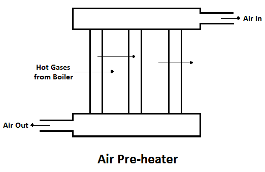
Fig 15
The advantages of air pre-heater are,
1) Increase in the steam generation rate.
2) Better combustion with less soot, smoke and ash, and
3) Low-grade fuels can be used.
The main objective of feed water heater is to heat feed water with the help of steam extracted or bled from the various intermediate stages of the turbine. This heating arrangement of feed water is called regenerative feed water heating and the heater known as regenerative feed water heater. Regenerative feed water heater improves thermal efficiency.It protects the condenser by removing air which leaks the condenser.It is necessary to prevent corrosion into the boiler.In this page, we are going to discuss the different types of feed water heater and their heating arrangements.
Feed water heater is two types.These are:
1).Open feed water heater
2).Closed feed water heater
In open feed water heater, extracted steam is mixed with feed water at the same pressure and closed feed water heater, steam does not mix with feed water. There is a heat exchange between the two fluids at different pressure
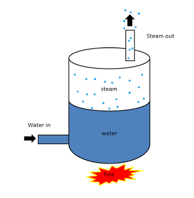
Fig 16
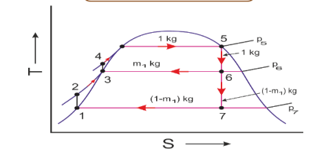
Fig 17
The above diagram shows regenerative type open feed water heater. Assume 1 kg of steam leaving the boiler and entering the turbine. Suppose m1 kg of steam is extracted or bled from the turbine at the intermediate pressure. During expansion from 5 to 6, 1 kg of steam is flowing through the turbine and (1-m1) kg is flowing through the remaining part of the turbine at the expansion from 6 to 7.
In open feed water heater, pump release (1-m1) kg feed water at point 2 which is mixed with m1 kg of extracted or bled steam at point 6. Now this mixing fluid is saturated water at point 3 position with intermediate pressure p6. The m1 of steam can be found by SSSF energy equation.

So, heat added (qH):

Work done in turbine (wT):

Pump work (wP):

It is seen from the above equation that feed water enters the boiler at a higher temp T4 in place of T2. Since qh is reduced,wT and qL both are reduced.So, overall thermal efficiency of feed water nth is increased.
We can increase the thermal efficiency by adding feed water heater in this cycle. It rise T4 and nth. But adding feed water will increase the initial capital lost of any plant. Not only that, pressure drop in heaters,piping etc may offset the gains in thermal efficiency.as many as eight no of feed water is used today in major plants.
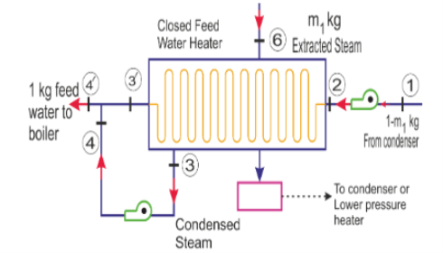
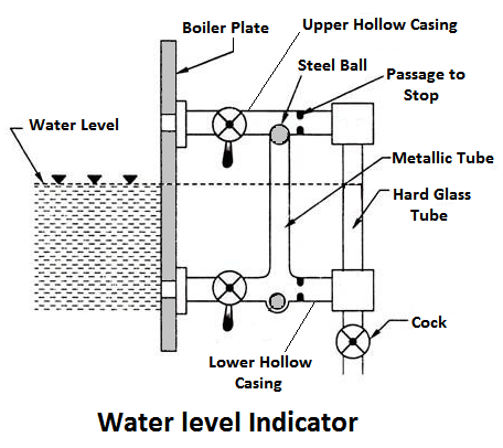
Fig 18
Above diagram shows closed feed water heater and T-S curve. Feed water enters to the heater at point 2 and it is heated from T2 to T3/ by the condensation of bled steam from 6 to 3. The condensed steam at the intermediate pressure is required to be pumped back into the feed line to state 4 at the boiler pressure before being mixed with the feed water at 3/. Now the mixed steam at 4/ enters the boiler. So m1 is-

The point 3, 3/, 4, 4 coincide each other from same temperature and entropy.
Design and construction is simple both open and closed feed water heater. One additional pump can be used for both feed water heaters for condensed steam. But in closed feed water heater, the condensed steam can be eliminated by the use of a steam trap and throttle valve shown in the diagram. It allow to pass only liquid not vapour.
The superheater is used in boilers to increase the temperature of the steam about the saturation temperature.
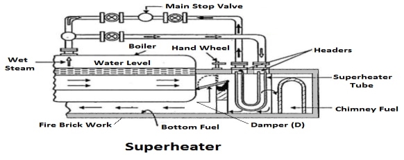
Fig 19
The dry saturated steam generated in the boiler is passed through a set of tubes placed in the path of the flue gases, in which it will be heated further by the hot gas to increase its temperature about the saturation temperature.
The efficiency is defined as ratio of heat output to the heat input in percentage.
Some controversy exists at present among engineers as to whether the boiler efficiency should be expressed in terms of the gross calorific value of the fuel as fired, or its net calorific value, or “by difference”.
The gross calorific value is, of course, the total heating value of the fuel per unit of weight or volume, including the heat of oxidation of the hydrogen in the fuel to water (steam) plus the latent heat of the total moisture in the fuel. On the other hand, the net calorific value of the same fuel is the total heating value of the combustible elements only, and excludes the heat of formation of water from the hydrogen and the evaporation of the moisture in the fuel to steam.
Some engineers prefer to quote their boiler efficiencies “by difference”, which means that the figure is obtained by subtracting all the accounted heat losses from a hundred. The boiler efficiency expressed in this way includes all the losses which cannot be determined; thus it gives an exaggerated value. It also assumes that all the measured losses have been correctly determined.
The percentage of total heat exported by outlet steam in the total heat supplied by the fuel (coal) is called steam boiler efficiency.
Steam boiler efficiency (%) = (heat exported by outlet steam/ heat supplied by the fuel) x 100
It includes with thermal efficiency, combustion efficiency and fuel to steam efficiency. Steam boiler efficiency depends upon the size of boiler used. A typical efficiency of steam boiler is 80% to 88%. Actually there are some losses occur like incomplete combustion, radiating loss occurs from steam boiler surrounding wall, defective combustion gas etc. Hence, efficiency of steam boiler gives this result.
Boiler efficiency is a combined result of efficiencies of different components of a boiler. A boiler has many sub systems whose efficiency affects the overall boiler efficiency. Couple of efficiencies which finally decide the boiler efficiency are-
Apart from these efficiencies, there are some other losses which also play a role while deciding the boiler efficiency and hence need to be considered while calculating the boiler efficiency.
Combustion Efficiency
The combustion efficiency of a boiler is the indication of burner’s ability to burn fuel. The two parameters which determine the burner efficiency are unburnt fuel quantities in exhaust and excess oxygen levels in the exhaust. As the amount of excess air is increased, the quantity of unburnt fuel in the exhaust decreases. This results in lowering the unburnt fuel losses but elevating the enthalpy losses. Hence, it is quite important to maintain a balance between enthalpy losses and un burnt losses. Combustion efficiency also varies with the fuel being burnt. Combustion efficiency is higher for liquid and gaseous fuels than for solid fuels.
Thermal Efficiency
The thermal efficiency of a boiler specifies the effectiveness of the heat exchanger of the boiler which actually transfers the heat energy from fireside to water side. Thermal efficiency is badly affected by scale formation/soot formation on the boiler tubes.
Direct and Indirect Boiler Efficiency
The overall boiler efficiency depends on many more parameters apart from combustion and thermal efficiencies. These other parameters include ON-OFF losses, radiation losses, convection losses, blow down losses etc. In actual practice, two methods are commonly used to find out boiler efficiency, namely direct method and indirect method of efficiency calculation.
Direct efficiency
This method calculates boiler efficiency by using the basic efficiency formula-
η=(Energy output)/(Energy input) X 100
In order to calculate boiler efficiency by this method, we divide the total energy output of a boiler by total energy input given to the boiler, multiplied by hundred.
Calculation of direct efficiency-
E= [Q (H-h)/q*GCV]*100
Where,
Q= Quantity of steam generated (kg/hr)
H= Enthalpy of steam (Kcal/kg)
h= Enthalpy of water (kcal/kg)
GCV= Gross calorific value of the fuel.
Indirect Efficiency
The indirect efficiency of a boiler is calculated by finding out the individual losses taking place in a boiler and then subtracting the sum from 100%. This method involves finding out the magnitudes of all the measurable losses taking place in a boiler by separate measurements. All these losses are added and subtracted from 100% to find out the final efficiency. Blow down valve is kept closed during the procedure. This method should be implemented as per the norms provided in BS845 standards. The losses calculated include stack losses, radiation losses, blow down losses etc.
Comparison of direct and indirect efficiency-
Both the methods of finding out boiler efficiency mentioned above have some advantages and some disadvantages associated with them. The greatest advantage of indirect method is that it also speaks about the sources of losses. By finding out indirect efficiency, one can come to know where the losses are increased and can be reduced. On the other hand, direct efficiency values are closer to reality as compared to indirect efficiency on account of uncovered losses such as radiation losses, ON-OFF losses etc. But direct efficiency can only tell us about the magnitude of overall loss. No information about individual losses and their magnitudes is conveyed from direct efficiency calculation. There always exists some difference in the values of direct and indirect efficiencies. Indirect efficiency is measured at a particular time whereas direct efficiency is measuredover a period of time and hence, losses on account of fluctuating loads, boiler on-off etc. is also taken into consideration.
Key point:
1) The efficiency is defined as ratio of heat output to the heat input in percentage.
2) Steam boiler efficiency (%) = (heat exported by outlet steam/ heat supplied by the fuel) x 100
3) Direct efficiency = η= (Energy output)/ (Energy input) X 100
Equivalent Evaporation might be more simply defined as “the quantity of water at 100°C that a boiler can convert into dry/saturated steam at 100°C from each kJ of energy that is applied to it. This defines it in terms of kg (of water/steam) per kJ of energy. However it is sometimes defined in units of kg water per kg of fuel, and (as in the case of the graph above) kg water/steam per hour.
The equivalent evaporation may be defined as: the amount of water evaporated from water at 100°C to dry and saturated steam at 100°C.
“Consider a boiler generating ma kg of steam per hour at a pressure p and temperature T.
Let h = Enthalpy of steam per kg under the generating conditions.
Then heat gained by the steam from the boiler per unit time = ma x (h – hf1)
The equivalent evaporation (me) from the definition is obtained as:

The evaporation rate of the boiler is also sometimes given in terms of kg of steam /kg of fuel. The presently accepted standard of expressing the capacity of a boiler is in terms of the total heat added per hour.
“For comparing the capacity of boilers working at different pressures, temperatures, different final steam conditions etc, a parameter called “equivalent evaporation” can be used. Equivalent evaporation actually indicates the amount of heat added in the boiler for steam generation. Equivalent evaporation refers to the quantity of dry saturated steam generated per unit of time from feedwater at 100°C to steam at 100°C at the saturation pressure corresponding to 100°C. Sometimes it is called equivalent evaporation from and at 100°C. Thus mathematically it could be given as:
For a boiler generating steam at ‘m’ kg/h at some pressure ‘p’ and temperature ‘T’, the heat supplied for steam generation = m x (h – hw), where h is the enthalpy of final steam generated and hw is enthalpy of feedwater. Enthalpy of final steam shall be:
Equivalent evaporation (kg/kg of fuel) =
Equivalent evaporation is thus a parameter which could be used for comparing the capacities of different boilers.”
Boiler Trial
Boiler trials are carried out to determine the thermal efficiency of the boiler and to draw up the heat balance account. Boiler trials are also carried out to verify the guaranteed maximum evaporative capacity of the boiler. For complete boiler trial, it is necessary to measure losses in addition to the heat utilised in raising steam. Such trials have been the direct cause of and incentive to the improvement of boilers. The measurements necessary to determine the thermal efficiency of a boiler and to draw up the heat balance account for a boiler are:
1) Rate of fuel consumption, i.e. mass of fuel burned/hr
2) Calorific value and chemical analysis of fuel after proper sampling,
3) Rate of water evaporation, i.e. mass of water evaporated/hr.,
4) Pressure of steam at the boiler stop valve,
5) Condition of steam at the boiler stop valve, i.e. dryness fraction of steam if there is no superheaters or temperature of steam if there is a superheater,
6) Feed water temperature,
7) Flue gases temperature,
8) Analysis of flue gases,
9) Mass of ashes and determination of their calorific value after proper sampling, and
10) Measurement of pressure, temperature and humidity of air.
To get the best outcomes from a preliminary on the steam kettle, extraordinary consideration should be paid to the technique for stirring up. The technique for beginning and halting the preliminary, and the span of the preliminary are additionally vital. The choices with respect to these altogether rely on the conditions under which the evaporator needs to work.
The accompanying strategy for beginning and halting the preliminary will by and large be discovered the most convenient:
The boiler ought to be continued running on burden for quite a while to get settled down to working conditions. Around fifteen minutes before the preliminary initiates, the fire ought to be cleaned and all cinders and clinker eliminated. At that point, toward the beginning of the preliminary the thickness of the fire, the steam pressure and the temperature of the pipe gases ought to promptly be noted. The water level be set apart by tying a piece of string around the check glass, and the feed siphon ought to be halted. Toward the finish of the preliminary, the thickness of the fire, the steam pressure and the temperature of the vent gases ought to be same as that toward the beginning of the preliminary. On the off chance that the water level of the feed water tank and evaporator water tank and kettle water check glass is the equivalent toward the end as toward the beginning of the preliminary, the working of result is quite improved.
The term of the preliminary will rely primarily on the greatness of the blunder prone to be made in making a decision about the thickness and state of the fire toward the beginning and end of the preliminary, when contrasted with the mass of fuel terminated during the preliminary. The length of preliminary ought not, generally speaking, be under six hours.
The accompanying estimations and readings ought to be taken to decide the warm productivity and to draw up the warmth balance represent the evaporator:
1. The fuel ought to be weighted out in helpful bunches of, from 20 to 400 kg relying on the limit of the heater. This ought to be finished by utilizing two boxes. At the hour of beginning of the preliminary, the main part (box) ought to be discharged on the floor and stirring up initiated. A total record of season of exhausting the containers might be kept on a log sheet.
2. An example ought to be taken from each part of fuel weighted out and towards the finish of the preliminary the examples ought to be separated into little pieces and all around blended, and two agent tests be taken - one for the assurance of its calorific worth (by utilizing' the Bomb calorimeter) and the other for substance examination.
3. Some kind of volumetric estimation is utilized for estimating the feed water provided to the evaporator. Different techniques might be received for the reason. For little size boilers, one feed tank is utilized, while for huge size boilers, two tanks might be utilized, each fitted with a measure glass and precisely adjusted. Not long before the preliminary begins the feed siphon ought to be halted and the water level in the feed tank ought to be checked and recorded if just one feed tank is utilized. The feed siphon is then begun. The distinction in water levels toward the beginning and end of the preliminary gives the measure of feed water utilized. In the event that if two tanks are utilized, not long before the initiation of the preliminary, No. 1 tank ought to be topped off, the heater being taken care of from No. 2 tank. Toward the start of the preliminary the heater is taken care of from No. 1 tank and No. 2 tank being topped off. The quantity of topping off of tanks relies absolutely upon the size of the heater and the span of the preliminary.
4. Readings ought to be required like clockwork of the steam pressure measure.
5. Estimations with respect to state of steam at the kettle stop valve are finished
Precisely in comparative way concerning state of steam at motor stop valve portrayed before in this section under steam motor preliminary.
6. The temperature of feed water provided to the kettle is estimated at customary time period minutes by methods for conventional mercury glass thermometer. With the end goal of figuring of feed water temperature, normal perusing of the temperature is thought of.
7. The temperature of the pipe gases is most precisely estimated by a pyrometer.
This ought to be set at the lower part of the stack and close to the damper on the chimney stack side. Readings are taken at normal time timespan minutes and normal worth is considered with the end goal of count of warmth diverted by the pipe gases.
8. The example of vent gases ought to be taken simply on the chimney stack side of the damper at a similar spot at which the temperature of pipe gases is estimated. At the point when the heater under test is terminated by mechanical stokers, the pipe gas test might be drawn straightforwardly into the breaking down contraption, yet when terminating is by hand, ceaseless assortment is important to make sure about a normal example. At the point when extraordinary exactness is required, the vent gases should gathered over mercury, yet refined water which has been soaked with basic salt, or water with a layer of oil on the top, will give results precise enough for most purposes. The vent gas is helpfully dissected on the spot by methods for Orsat mechanical assembly portrayed in part 7 of volume I.
9. The measure of remains shaped during the time for testing is gotten by gauging the
Remains shaped in the debris pit toward the finish of preliminary. As on account of fuel, agent Test of the debris is acquired and its calorific worth is controlled by utilizing the Bomb calorimeter.
10. Normal estimations of temperature and pressing factor of the kettle house are gotten by perusing a thermometer and an indicator at standard time frame minutes, to gauge the mugginess (dampness) in the quality of the evaporator house readings of the dry and wet bulb thermometers are taken at ordinary time span.
Heat balance
A heat asset report shows the total record of warmth provided by 1 kg of dry fuel and warmth burned-through. The warmth provided is utilized for expanding the steam and the excess warmth is lost. We realize that warmth utilized in expanding steam/kg of fuel,

The Heat Balance Equation
Q = Q1 + (Q2 +Q3 + Q4 +Q5 + Q6) where:
Q= available heat of burnt fuel
Q1= heat absorbed by working fluid
Q2 to Q6 = heat losses
Dividing both sides by Q and expressing as a %age we get:
100 = q1 +(q2 +q3+q4+q5+q6)
Key points
1) A heat balance sheet shows the complete account of heat supplied by 1 kg of dry fuel and heat consumed.
2) The boiler should be kept running on load for some time in order to get settled down to working conditions.
3) The temperature of the flue gases is most accurately measured by a pyrometer
Condenser is a heat exchanging apparatus used to condense substance in a gaseous state to its liquid state by cooling. The heat (latent heat) from vapour/ gaseous substance is removed first by the walls of the condenser tube. then from tube to surrounding environment/ cooling medium. The common cooling medium is air or water or a combination of them. The size of condenser unit may vary from small handheld to the large industrial scale unit. The selection of condenser depends on the application, type of gas to be condense and the type of cooling medium.
The refrigeration unit uses a small air cooled condenser to get rid the heat absorbed from interior to the outside air. In an industrial process such as power plant uses large water cooled condenser. The water-cooled condenser operates at much lesser temperature than air cooled condenser.
The primary functions of the Condensing plant are:
Classification of condenser
These are the three basic types of condensers
According to the condensing (cooling) medium used condensers are classified into:
1. Air cooled condenser: Air is used as condensing medium. It is the easiest arrangement.
2. Water cooled condenser: Water is used to removal of heat. Water cooled condenser is the most efficient.
3. Evaporative condenser: Both air and water is used as condensing medium. Evaporative condensers are least popular.
According the contact between condensate and condensing medium
1. Jet condenser/ mixing type condenser: Also called direct contact condenser. There is direct contact/ mixing between condensate and condensing medium.
2. Surface condenser/ non-mixing type condenser: Also called indirect contact condenser. There is no contact between condensate and condensing medium, there is a barrier/ surface (eg: tube wall) between them.
According to condensing medium flow
1. Natural convection condenser: the movement of condensing medium is completely by the natural convection.
2. Forced convection condenser: the condensing medium is forced to flow through the condenser by using means such as fans, pumps.

Fig 20
We are going to study the air leakage in the condenser so, let’s first understand why air leakage occurs in the condensers? The main objective of the condenser is to reduce the pressure of the steam to increase efficiency.
The condenser has a high vacuum. The air always moves from higher pressure to the lower pressure and the pressure in the condenser is very low (high vacuum) therefore, air leakage occurs in the condenser. The main sources of air leakage in condensers are stated below:
Now, let’s understand each point in detail. Air leakage can take place through various joints, packing and glands due to the high vacuum in the condenser. We can prevent this by using vacuum joints and keeping all the joints tight and sealed
Air dissolved in feed waterWhen air dissolved feed water enters into the boiler and after the conversion of feed water into steam, it enters the condenser along with the exhaust steam which causes air leakage in the condenser. We can prevent this by treating the feed water before entering the boiler.
Air dissolved with injection water to condenserWe know that Jet condensers are mixing type condensers in which cooling water comes in direct contact with the steam, air can enter the condenser along with the cooling water which is supplied externally for the condensation process.
Effects of Air leakage
Prevention of Air Leakage in the Condenser:
In order to prevent the sources of leakage in the condenser the following procedure is adopted:
(i) The design of condenser and use of vacuum joints.
(ii) By giving treatment of feed water to the boiler.
(iii) Keeping the entire joint tight and sealed.
Detection of Air Leakage in the Condenser:
The air leakage can be detected by:
(i) Keep condenser under pressure and apply soap water at the joints where the infiltration is possible.
(ii) Use Peppermint oil on the suspected joints during condenser operation and check on the odour in the discharge of the air ejector.
(iii) The large leakages can be detected by moving candle flame over the possible opening.
Condenser performance is highly crucial for efficient operation of the power plant as major share of heat rejection takes place here. Many of the old power plants do not have necessary systems in place for acomprehensive assessment of the condenser performance on a regular basis. The study proposes to carry out unit specific studies at two power stations to identify methodology for on line monitoring of condenser parameters to evaluate its thermal and physical performance in an economical way. Such evaluation would enable them in taking a conscious decision for possible intervention atan appropriate time.
Justification
Studies have shown that major deviations from design/targetsvalues of the heat rate are to a great extent due to under performance of the condenser largely reflected innon- achieving the desired vacuum. For example, about 60 units of 210/500 MW capacity mapped with Epsilon softwarehas shown adeviation of the order of 3-5%. Condenser contribution was about 15% inunit heat rate loss. Some of the reasons for poor performance include blocked tubes, flooding of tubes, excessive air leakage, tube fouling/leakages etc.as a result of both thermal and physical deterioration.
The thermal performance can be best evaluated by regular monitoring of various parameters such as condensate temperature, CW inlet/ outlet temperature CW flowetc., and analysing heat transfer coefficient terminal temperature difference ,sub coolingetc.
The thermal performance evaluation can be further supplemented through various parameters such as:
1) Air leakage determination
2) Cooling water side hydraulic loss
3) Assessment of tube cleaning arrangement
4) Electrical conductivity / oxygen content in the condensate
5) Copper content in the cooling water ( for copper alloy materials of condenser tubes)
The study would involve review of various parameters / methods of condenser monitoring evaluate the trends and make recommendations inregard to measurements, evaluation methods and suggest actions for attaining condenser performance to be within expected tolerances.
Broad scope of work
The scope of work would cover the following:
1) Review of design data/performance guarantee test
2) Study of plant performance w.r.t cooling water system of 2-3 yearsperformance and other historical data
3) Site visit, measurements as required and discussions with plant engineers
4) Performance Evaluation
5) Trend analysis for aperiod of I month
6) Assessment of impact of deviations on condenser/ unit performance
7) Recommendations for sustained improved plant performance
8) Development of guidelines in respect of measurements required method of analysis interpretation of results and actions required.
Deliverables
The study would enable to have a comprehensive document about a cost effective approach for existing old plants to regularly monitor the condenser performance and provide guidance for effective intervention. The results would be shared with various utilities for wider adoption.
Reference
1) Engineering thermodynamics P.K nag
2) I.C engineering =m.l mathur
3) https://www.physicsforums.com/attachments/flow-calculations-pdf.20219/
4) https://onlinelibrary.wiley.com/doi/pdf/10.1002/0471743984.vse7245
