Unit-4
Steam and Gas Nozzles
Nozzles are actually used to modify the flow of a fluid (i.e. by increasing kinetic energy of the flow in expense of its pressure). Convergent-divergent type of nozzles are mostly used for supersonic flows because it is impossible to create supersonic flows (mach number more than one) in convergent type of nozzle and therefore it restricts us to a limited amount of mass flow through a particular nozzle. In convergent-divergent type of nozzles we can increase the flow velocity much higher than sonic velocity that is why these type of nozzles have a wide applications such as propelling nozzles in jet engines or in air intake for engines working at high rpms.
For understanding the working principle of convergent-divergent type of nozzles, first we need to look the working principle of only convergent type of nozzles.In these type of nozzles the area of the nozzle reduces gradually in the direction of flow.The pressure at intake is called stagnation pressure and the pressure at exit is called back pressure.The value of back pressure can never be more than 1 in case of a nozzle. As we start reducing the back pressure we observe that flow velocity and mass flow rate also starts increasing, but this will happen up to a certain limit, after which no increase in velocity or mass flow rate takes place. This situation is known as choked i.e. no further increase in mass flow rate takes place whatever be the back pressure now. This situation takes place at a particular mach number i.e. at mach number '1'.
But the case is not the same when we use a divergent nozzle just after the convergent. Actually the principle reverses i.e. when we attach a divergent nozzle just after the convergent nozzle our flow speed starts increasing with the decrease in back pressure and also the mass flow rate. And therefore in this type of nozzles we can reach to the speeds above sonic i.e. supersonic.
Mach number:
It is the ratio of speed of flow in a medium to the speed of sound in that medium
For Mach numbers ≤ 0.3 we consider the flow to be incompressible because the density variation is below 5% and for flows having Mach number ≥ 0.3 we consider the flow to be compressible because the density variation cannot be neglected now. For supersonic flows increase in velocity causes flow velocity to increase. And therefore for our case i.e. supersonic flows we will be doing all he calculations considering compressible flow only.
Normal Shock:
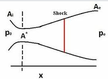
It is a completely irreversible process takes place in the Convergent divergent type of nozzles (or in venturi) at the divergent section. A sudden change in pressure, temperature, and flow velocity takes place while supersonic flow was taking place. After shock flow becomes subsonic and stays subsonic till end. Width of this shock is very less i.e. about 4 times the mean free path of the gas molecules.
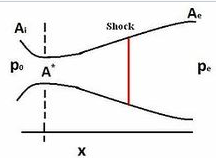
Shock pictures
Shock
Fig 1
m= mass flow rate
V= velocity
ρ= density
γ= specific heat ratio
A= area
M= Mach number
a= speed of sound
p-Difference in pressures on body
V-velocity of fluid surrounding the body
g-Acceleration due to gravity
z-height of body
po - stagnation pressure
pc - back pressure
A - Area at exit of nozzle
A*- Area at throat
Conservation of mass::
m=
ρx V x A
Conservation of momentum:
Ρ x V x dV = -d
Isentropic steady flow:
Bernoulli's principle:
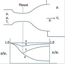
Figure 1shows the flow through the nozzle when it is completely subsonic (i.e. the nozzle isn't choked). The flow accelerates out of the chamber through the converging section, reaching its maximum (subsonic) speed at the throat. The flow then decelerates through the diverging section and exhausts into the ambient as a subsonic jet. Lowering the back pressure in this state increases the flow speed everywhere in the nozzle.

Fig .1 Subsonic flow
Lower it far enough and we eventually get to the situation shown in figure 2. The flow pattern is exactly the same as in subsonic flow, except that the flow speed at the throat has just reached Mach 1. Flow through the nozzle is now choked since further reductions in the back pressure can't move the point of M=1 away from the throat. However, the flow pattern in the diverging section does change as you lower the back pressure further.
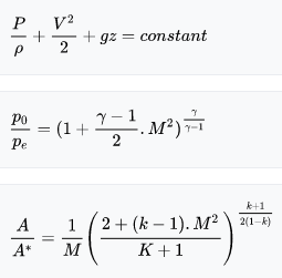
Fig 2 Flow just choked
As pb is lowered below that needed to just choke the flow a region of supersonic flow forms just downstream of the throat. Unlike a subsonic flow, the supersonic flow accelerates as the area gets bigger. This region of supersonic acceleration is terminated by a normal shock wave. The shock wave produces a near-instantaneous deceleration of the flow to subsonic speed. This subsonic flow then decelerates through the remainder of the diverging section and exhausts as a subsonic jet. In this regime if you lower or raise the back pressure you increase or decrease the length of supersonic flow in the diverging section before the shock wave.
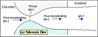
Fig 3 Shock in nozzle
If you lower pb enough you can extend the supersonic region all the way down the nozzle until the shock is sitting at the nozzle exit (figure 4). Because you have a very long region of acceleration (the entire nozzle length) in this case the flow speed just before the shock will be very large in this case. However, after the shock the flow in the jet will still be subsonic.
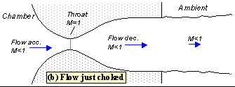
Fig 4 shock at exit
Lowering the back pressure further causes the shock to bend out into the jet (figure 5), and a complex pattern of shocks and reflections is set up in the jet which will now involve a mixture of subsonic and supersonic flow, or (if the back pressure is low enough) just supersonic flow. Because the shock is no longer perpendicular to the flow near the nozzle walls, it deflects it inward as it leaves the exit producing an initially contracting jet. We refer to this as over expanded flow because in this case the pressure at the nozzle exit is lower than that in the ambient (the back pressure)- i.e. the flow has been expanded by the nozzle to much.
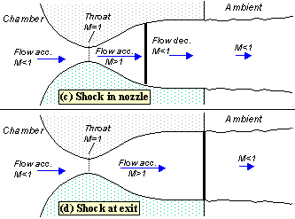
Fig 5 overexpanded
A further lowering of the back pressure changes and weakens the wave pattern in the jet. Eventually we will have lowered the back pressure enough so that it is now equal to the pressure at the nozzle exit. In this case, the waves in the jet disappear altogether (figure 6), and the jet will be uniformly supersonic. This situation, since it is often desirable, is referred to as the 'design condition'.
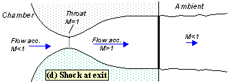
Fig 6 Design condition
Finally, if we lower the back pressure even further we will create a new imbalance between the exit and back pressures (exit pressure greater than back pressure), figure 7. In this situation (called 'underexpanded') what we call expansion waves (that produce gradual turning and acceleration in the jet) form at the nozzle exit, initially turning the flow at the jet edges outward in a plume and setting up a different type of complex wave pattern.
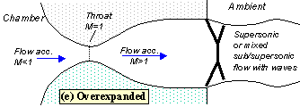
Fig 7 Under expanded
The pressure distribution in the nozzle
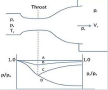
A plot of the pressure distribution along the nozzle (figure 8) provides a good way of summarizing its behaviour. To understand how the pressure behaves you have to remember only a few basic rules
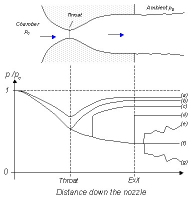
Fig 8 Pressure distribution along the nozzle labels refer to flow regimes
When the flow accelerates (sub or supersonically) the pressure drops The pressure rises instantaneously across a shock The pressure throughout the jet is always the same as the ambient (i.e. the back pressure) unless the jet is supersonic and there are shocks or expansion waves in the jet to produce pressure differences. The pressure falls across an expansion wave.
The labels on figure 8 indicate the back pressure and pressure distribution for each of the flow regimes illustrated in figure 3. Notice how, once the flow is choked, the pressure distribution in the converging section doesn't change with the back pressure at all.
Key points
1) When the flow accelerates (sub or supersonically) the pressure drops The pressure rises instantaneously across a shock
2) The pressure falls across an expansion wave
3) Mach number: It is the ratio of speed of flow in a medium to the speed of sound in that medium
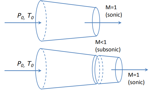
Sonic velocity will occur at the exit of the converging extension, instead of the exit of the original nozzle, and the mass flow rate through the nozzle will decrease because of the reduced exit area.
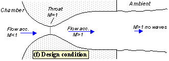
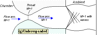
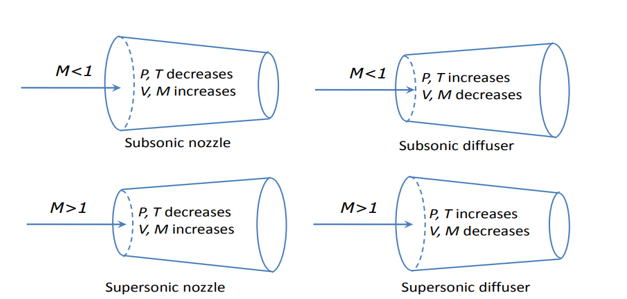
Fig 9 variation of velocity
In converging sections (dA<0):
o When the flow is subsonic (M<1→(1−M2)>0): speed increases (dv>0), Mach-number increases (dM>0), but pressure and temperature decrease.
o When the flow is supersonic (M>1→(1−M2)<0): speed decreases (dv<0), Mach-number decreases (dM<0), but pressure and temperature increase.
• In diverging sections (dA>0):
o When the flow is subsonic (M<1→(1−M2)>0): speed decreases (dv<0), Mach-number decreases (dM<0), but pressure and temperature increase.
o When the flow is supersonic (M>1→(1−M2)<0): speed increases (dv>0), Mach-number increases (dM>0), but pressure and temperature decrease.
A = cross-sectional area of nozzle passage at a given downstream location in nozzle
A* = cross-sectional area of nozzle throat
M = Mach number of flow at a given downstream location in nozzle
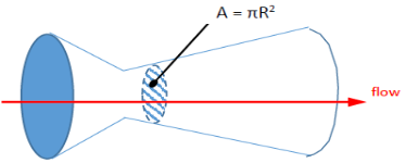
Fig 10 Nozzle
For this example, we’ll assume k = 1.15
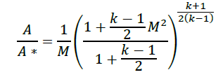
The equation that relates area ratio to Mach number is
The suggested first step is to simplify the calculation by calculating the terms involving “k”
To plot the results on a graph, area ratios for Mach numbers from 0 to 3.00 are calculated, at step sizes of 0.2.
Note that for M=0, the term 1/M is undefined (cannot divide by zero) so we’ll start with M=0.2
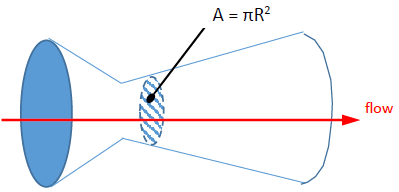
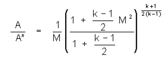
Using a spread sheet program such as Excel makes short work of doing these calculations. Excel is used to generate the graph. The final results and graph are shown below.
Note that both Mach number and area ratio are dimensionless.
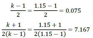
Fig 11
Choked Flow” is a fluid dynamic condition associated with the venturi effect.Fluid flow through a restricted area whose rate reaches a maximum when the fluid velocity reaches the sonic velocity at some point along the flow path. The phenomenon of choking exists only in compressible flow and can occur in several flow situations.
Consider a fluid (liquid/gas) flowing through a venturi or a convergent-divergent nozzle as shown below.
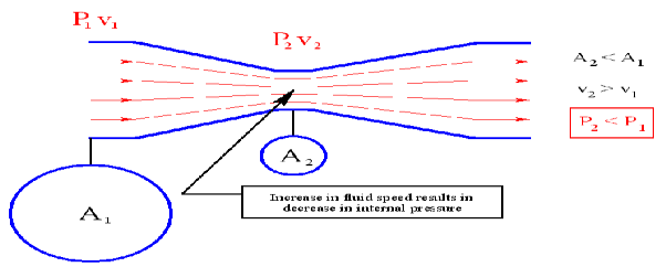
Fig 12 choked flow
Assume that P1 is constant. As the fluid travels through the “constriction”, its velocity increases (according to conservation of mass principle). Simultaneously, the static pressure of the fluid P2 decreases. This is a well-established principle.
Now, let us increase the mass flow rate of the fluid entering the venturi while keeping P1 constant. This will lead to increase in velocity v1. This will also increase the velocity v2 at the exit of the constriction.
Now, keep on increasing the mass flow rate of the fluid gradually while keeping P1 constant. You will always notice that both v1 and v2 increase gradually; but this works only up to a certain mass flow rate. After this point, increasing the mass flow rate without changing the pressure P1 is not possible. Thus, the mass flow rate has reached its limiting value. This condition is called as “Choked Flow”. The mass flow rate at choking point depends on the pressure and temperature of the fluid entering the venturi/nozzle. Usually choking occurs when the exit velocity v2 of the fluid reaches the speed of Mach 1.
Choked flow can occur through a convergent flow area or nozzle attached to a huge reservoir. Flow exits the reservoir through the nozzle if the back pressure is less than the reservoir pressure. When the back pressure is decreased slightly below the reservoir pressure, a signal from beyond the nozzle exit is transmitted at sonic speed to the reservoir.
The reservoir responds by sending fluid through the nozzle. Further, the maximum velocity of the fluid exists at the nozzle throat where the area is smallest. When the back pressure is further decreased, fluid exits the reservoir more rapidly. Eventually, however, the velocity at the throat reaches the sonic velocity. Then the fluid velocity at the throat is sonic, and the velocity of the signal is also sonic. Therefore, further decreases in back pressure are not sensed by the reservoir, and correspondingly will not induce any greater flow to exit the reservoir. The nozzle is thus said to be choked, and the mass flow of fluid is a maximum.
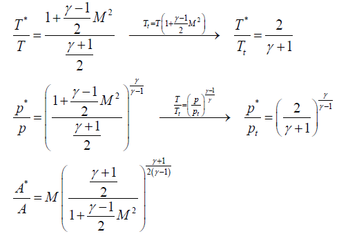
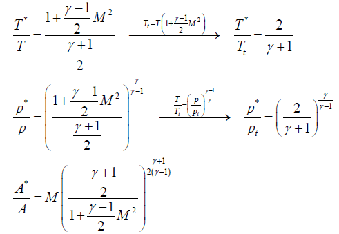
Going on with gas flow and leaving liquid flow aside, we may notice that M=1 can only occur in a nozzle neck, either in a smooth throat where dA=0, or in a singular throat with discontinuous area slope (a kink in nozzle profile, or the end of a nozzle). Naming with a '*' variables the stage where M=1 (i.e. the sonic section, which may be a real throat within the nozzle or at some extrapolated imaginary throat downstream of a subsonic nozzle), equations are:
where the expressions for total temperature Tt and total pressure pt has been substituted to show that temperature and pressure at the throat (also known as critical values), are just a function of γ, since, for isentropic flows, total conditions do not change along the stream. Although the equations above apply to all 1D isentropic perfect-gas flows.
Key points
1) Choked Flow” is a fluid dynamic condition associated with the venturi effect.
2) Choked flow can occur through a convergent flow area or nozzle attached to a huge reservoir.
The smallest cross-sectional area of the nozzle is called the throat of the nozzle.
If the nozzle is convergent, the nozzle terminates at the throat hence the throat is the exit end or mouth of the nozzle.
If the nozzle is convergent-divergent, calculation of throat area is the same as for the convergent nozzle in which case the value of p2 is critical pressure.
Nozzle efficiency
In nozzle, the wall friction is small in convergent portion as compared to divergent portion. The friction losses in the nozzle depend upon the type of material, size, and shape, properties of the fluid and flow conditions is nozzle.
The nozzle efficiency can be defined as the ratio of actual enthalpy drop to ideal (isentropic) enthalpy drop in nozzle.
Therefore
Nozzle efficiency, ηn = (Actual enthalpy drop) / (isentropic enthalpy drop)
ηn = (h1 – h2) / (h1 – h'2
The nozzle efficiency can be defined as the ratio of actual enthalpy drop to isentropic enthalpy drop.
Nozzle Efficiency of Steam Turbine:-
Nozzle efficiency of steam turbine is the ratio of energy supplied to the blades per kg of steam to the total energy supplied per stage per kg of steam.
The energy supplied to the blades per kg of steam

So,Nozzle Efficiency equation of steam turbine is,

Key points
1) The smallest cross-sectional area of the nozzle is called the throat of the nozzle.
2) Nozzle Efficiency equation of steam turbine

If you are a small person riding along a fluid particle that is supersonic, neither you nor the fluid particle you are hitching a ride on can see what is coming up ahead of you. There is no mechanism for you to see what is ahead and gradually slow down or correct course. You are now committed to a sudden, discontinuous change resulting in an increase in pressure and temperature, and a loss of speed. So, basically the idea of shockwaves is this: they are a discontinuity that forms in order for the flow to meet some downstream condition. If a supersonic flow never encounters something downstream, like an obstacle or a back pressure, it will never shock. And likewise, a subsonic flow can never form a shock wave (unless it is first accelerated to supersonic somewhere within the flow field). In subsonic flows, downstream obstacles and pressures are communicated upstream at a speed that allows for the curving of streamlines and/or deceleration. You can observe this by picturing the streamlines around an air foil that curve around its shape but never contact it.
Simple example of a shock-wave
Let’s look at (probably) the most common learning example: a shockwave forming in a supersonic nozzle.
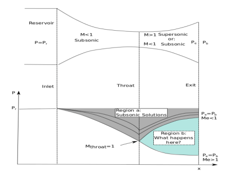
Fig 13) Nozzle flow schematic
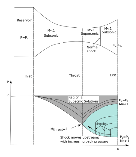
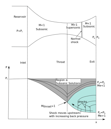
In Figure 13 we see the classic nozzle example. The main concept is this: When the back pressure is high enough, the flow through the nozzle never goes supersonic (including at the throat) and is simply compressed to the throat and then expanded in the diverging section (and in these cases Pe=Pb). These are the cases shown by Region a in the figure. When the back pressure (Pb) is low enough that the flow in the nozzle throat is choked (Mach 1 is achieved) there are now two possible solutions. The first solution is the subsonic solution. Here, the flow decelerates from Mach 1 to the exit and flow exits at M<1. The second solution is the supersonic solution. Here, the flow continues to accelerate and exits at M>1. When Pb is equal the supersonic back pressure, the flow will obey the supersonic solution. And similarly, when Pb is equal to the subsonic back pressure the flow will remain subsonic.
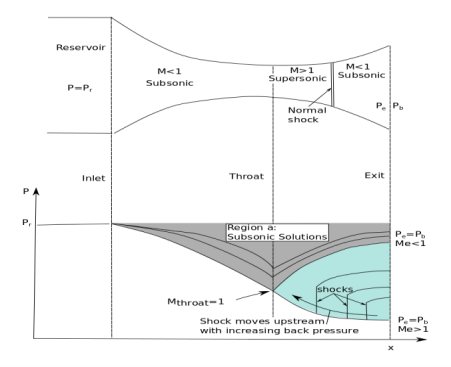
Fig 14) Nozzle flow shematic (with shocks)
Fig 14 shows what happens in Region b. As the back pressure is increased, the shock-wave that is formed moves upstream and is formed earlier in the nozzle. This continues until Pe=Pb(subsonic) and the shock disappears. Can you have a shock in the converging section? No. Not unless you had supersonic flow in the converging section in the first place.
Analysis of Normal Shock-waves
Normal shock waves are a one-dimensional, adiabatic, discontinuous phenomena that are governed by the equations of fluid mechanics (conservation of mass, momentum and energy).
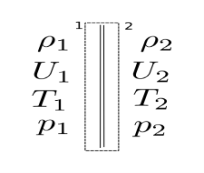
Fig 3) Normal Shock Control Volume Layout
The governing equations for the control volume above are:
Conservation of mass:
Conservation of momentum: 
Conservation of energy: 
Perfect gas equation of state assuming constant specific heats:

And 
With the above equations the problem is fully defined. It is then just a matter of an exercise in algebra. From various combinations of the above equations (its worth it to derive them yourself at some point… especially if you are studying for a PhD candidacy) the normal shock relations are obtained.
The normal shock relations are defined here:
Temperature Ratio: 
Pressure Ratio: 
Density and velocity ratio:
Stagnation Pressure Ratio:
Post-shock Mach number: 
Properties of the Normal Shock
1) Normal shock-waves obey conservation of mass, momentum, and energy, AND the 2nd law of thermodynamics. It may seem obvious but it should be re-stated. A shock-wave obeys the usual laws of fluid mechanics.
2) Shock-waves are adiabatic. when we analyse the control volume shown in Figure 3, Energy in=Energy out.
3) When you have a perfect gas with constant specific heats stagnation temperature does not change across the shock. This is really an extension of the last point. when the gas does not have constant specific heats, energy is still conserved but the stagnation temperature across the shock will change.
4) Stagnation pressure always decreases across a shock.
5) The Mach number always decreases across a shock. Additionally, for a normal shock the post-shock Mach number is always subsonic.
Key points
1) When the back pressure is high enough, the flow through the nozzle never goes supersonic (including at the throat) and is simply compressed to the throat and then expanded in the diverging section (and in these cases Pe=Pb).
2) Stagnation Pressure Ratio
The effect of friction would be similar to its effect in mechanics. Friction resists the motion of any object or substance. In case of nozzle, it will decrease the motion of flow that is it will decrease the velocity of flow, and as a result, actual velocity of flow would be less than theoretical velocity of flow through nozzle.
1) Entropy is increased.
2) Available energy is decreased.
3) Velocity of flow at throat is decreased.
4) Volume of flowing steam is decreased.
5) Throat area necessary to discharge a given mass of steam is increased.
Most of the friction occurs in the diverging part of a convergent-divergent nozzle as the length of the converging part is very small. The effect of friction is to reduce the available enthalpy drop by about 10 to 15%. The velocity of steam will be then.
V2= 4.72 √K (H1-H2)
Where, k is the co-efficient which allows for friction loss. It is also known as nozzle efficiency.
As steam expands in the nozzle, its pressure and temperature drop, and it is expected that the steam start condensing when it strikes the saturation line. But this is not always the case. Owing to the high velocities, the residence time of the steam in the nozzle is small, and there may not sufficient time for the necessary heat transfer and the formation of liquid droplets. Consequently, the condensation of steam is delayed for a little while. This phenomenon is known as super saturation, and the steam that exists in the wet region without containing any liquid is known as supersaturated steam.
The locus of points where condensation will take place regardless of the initial temperature and pressure at the nozzle entrance is called the Wilson line. The Wilson line lies between 4 and 5 percent moisture curves in the saturation region on the h-s diagram for steam, and is often approximated by the 4 percent moisture line. The super saturation phenomenon is shown on the h-s chart below:
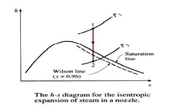
Fig 15
The steam turbine is one kind of heat engine machine in which steam's heat energy is converted to mechanical work.The construction of steam turbine is very simple.There is no piston rod,flywheel or slide valves attached to the turbine.So maintenance is quite easy.It consists of a rotor and a set of rotating blades which are attached to a shaft and the shaft is placed in the middle of the rotor.An electric generator known as steam turbine generator is connected to the rotor shaft.The turbine generator collects the mechanical energy from the shaft and converts it into electrical energy.Steam turbine generator also improves the turbine efficiency.
Classification of steam turbine
According to the working principle,there are different types of steam turbine.
1. According to the working principle steam turbines are mainly divided into two categories:
a)Impulse Turbine
b).Reaction Steam Turbine
⇨When steam strikes the moving blades through nozzles called Impulse Turbine and when it strikes the moving blades under pressure via guide mechanism called Reaction Turbine.
Steam turbines may be further divided into following categories:
2. According to the direction of steam flow, it may be classified into two categories:-
a).Axial Flow Steam Turbine:-
b).Radial Flow Steam Turbine:-
⇨ when the flow of steam inside the casing is parallel to the rotor shaft axis then it is called Axial Flow Steam Turbine and flow of steam inside the casing is radial to the rotor shaft axis called Radial Flow Steam turbine.
3. According to the exhaust condition of steam, it is further divided into two categories:-
a)Back Pressure or Non-Condensing types Steam Turbine:-
b)Condensing type Steam Turbine:-
⇨ after expansion of steam it is exhausted into atmosphere called back pressure steam turbine or non-condensing types steam turbine otherwise it exhausted into a condenser called condensing turbine.
4. According to pressure of steam, it may be divided following categories:-
a)High-pressure or pass-out or Extraction steam turbine:-
b)Medium-pressure or back pressure steam turbine:-
c)Low-pressure turbine:-
⇨ High, medium and low-pressure steam is supplied into the turbine, called high-pressure steam turbine or medium pressure steam turbine or back pressure steam turbine and low- pressure steam turbine.These turbines are used for various manufacturing and heating process.
5. According to the number of stages, it may be divided following categories:-
a) Single stage steam turbine:-
b)Multi-stage steam turbine:-
⇨ Steam is coming from nozzles when passed through a single set of moving blades called single stage steam turbine and to flow multi-stages of moving blades called multi-stages steam turbine.
6. According to the blade and wheels arrangement, it may be divided following categories:-
a) Pressure Compounding Steam Turbine
b)Velocity Compounding Steam Turbine
c)Impulse-Reaction Combined Steam Turbine
d)Pressure-Velocity Compounding Steam Turbine
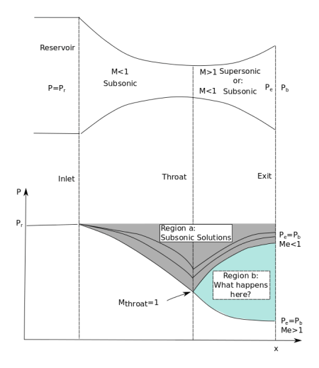
Fig 16 impulse and reaction turbine
Impulse Turbines:
The steam jets are directed at the turbines bucket shaped rotor blades where the pressure exerted by the jets causes the rotor to rotate and the velocity of the steam to reduce as it imparts its kinetic energy to the blades. The blades in turn change the direction of flow of the steam however its pressure remains constant as it passes through the rotor blades since the cross section of the chamber between the blades is constant. Impulse turbines are therefore also known as constant pressure turbines. The next series of fixed blades reverses the direction of the steam before it passes to thesecond row of moving blades.
i) Pressure drop takes place only in the nozzle and not in the moving blade. The pressure remains constant in the moving blade row.
ii. The area of blade channel at entrance and exit is same.
iii. Symmetrical profile type blades are used in impulse turbine which provides a uniform section. Impulse turbine may be either partial admission or full admission.
iv. This occupies less space for the same power.
v. Not much power can be developed.
vi. Efficiency is found low.
Vii. Suitable for small power generation.
viii. High rotor speed requires compounding of turbine.
Reaction Turbines
The rotor blades of the reaction turbine are shaped more like aero foils, arranged such that the cross section of the chambers formed between the fixed blades diminishes from the inlet side towards the exhaust side of the blades. The chambers between the rotor blades essentially form nozzles so that as the steam progresses through the chambers its velocity increases while at the same time its pressure decreases, just as in the nozzles formed by the fixed blades. Thus the pressure decreases in both the fixed and moving blades. As the steam emerges in a jet from between the rotor blades, it creates a reactive force on the blades which in turn creates the turning moment on the turbine rotor, just as in Hero’s steam engine. (Newton’s Third Law – For every action there is an equal and opposite reaction).
i. Pressure drop takes place in the fixed blade (nozzle) as well as in the moving blade row also.
ii. The area of blade channel at the exit is made narrow. It is of convergent type.
iii. Aerofoil types of blades are used in reaction turbine. Reaction turbine is always full admission turbine.
iv. This occupies more space for the same power.
v. Much power can be developed.
vi. High efficiency can be achieved.
Vii. Suitable for medium and high power generation.
viii. The speed is relatively low and hence no compounding is required.
Overall efficiency:
It has been shown that as a fluid expands through a turbine, there are friction effects between the
fluid and the enclosing boundary surfaces of the nozzles and blade passages. Further losses are
produced by leakage. Both of these are irreversibilities in the expansion process and there is a
reduction in the useful enthalpy drop in the case of a turbine. Refer to the Fig
Stage efficiency and reheat factor
The expansion of the fluid through the successive stages of a reaction turbine can be represented on
an h-s diagram as shown in Fig……. The procedure followed above for the whole turbine can be
applied to each stage separately, and the dotted line joins the points representing the state of the
steam between each stage. The dotted line is called the condition curve, although it does not give a
continuous state path since in between the known points the processes are irreversible.
Considering any one stage, the available enthalpy drop of the stage can be represented by
i
h
,
wher subscript I refers to any stage from 1 to n, and the isentropic enthalpy drop between the same
pressures can be represented by
si
h
. Then a stage efficiency can be defined as
Stage efficiency and reheat factor
The expansion of the fluid through the successive stages of a reaction turbine can be represented on an h-s diagram as shown in Fig. The procedure followed above for the whole turbine can be applied to each stage separately, and the dotted line joins the points representing the state of the steam between each stage. The dotted line is called the condition curve, although it does not give a continuous state path since in between the known points the processes are irreversible.
Considering any one stage, the available enthalpy drop of the stage can be represented by ∆hi, where subscript I refers to any stage from 1 to n, and the isentropic enthalpy drop between the same pressures can be represented by ∆hsi then stage efficiency can be defined as
From an inspection of Fig………, it is seen that BC <
2s
h
, etc. since the lines of constant
pressure diverge from left to right on the diagram
From an inspection of Fig. it is seen that BC <∆hs2 etc. since the lines of constant pressure diverge from left to right on the diagram.
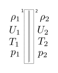
Fig 17

 And if it can be assumed that the stage efficiency is the same for each stage, then.


Where RF is the Reheat Factor.

is always greater than
0s
h
, it follows that R.F. is always greater than unity;
R.F. is usually of the order of 1.04 for a steam turbine.
 is always greater than ∆hso it follows that R.F. is always greater than unity; R.F. is usually of the order of 1.04 for a steam turbine.
Overall efficiency:
It has been shown that as a fluid expands through a turbine there are friction effects between the fluid and the enclosing boundary surfaces of the nozzles and blade passages. Further losses are produced by leakage. Both of these are irreversibilities in the expansion process and there is a reduction in the useful enthalpy drop in the case of a turbine.
The overall isentropic efficiency of a turbine is defined as
Overall efficiency,
The overall isentropic efficiency of a turbine is defined as
Overall efficiency = 
The overall efficiency so defined depends only on the change of properties of the fluid during the
expansion
The overall efficiency so defined depends only on the change of properties of the fluid during the expansion.
Gross or Stage Efficiency of Steam Turbine:-
Gross efficiency of steam turbine or stage efficiency of steam turbine is the ratio of the work done on the blades per kg of steam to the total energy supplied per stage per kg of steam.
Calculation of gross or stage efficiency of steam turbine is

Let, h1 = Enthalpy or total heat of steam before expansion through the nozzle in kJ/kg of steam, h2 = Enthalpy or total heat of steam after expansion through the nozzle in kJ/kg of steam,
Enthalpy or heat drop in the nozzle ring of an impulse wheel,
Total energy supplied per stage = 1000 hd J/kg of steam
Work done on the blade per kg of steam,

Gross or stage efficiency

We know that the Gross efficiency is the multiplication of blading efficiency and stage efficiency
Stage efficiency = blading efficiency x nozzle efficiency
Bleeding
In regenerative heating, some steam is carried out from the turbine at certain points during its expansion. This team is used to the feed water in the feed water heater increasing its temperature and then supplying to the boiler is known as bleeding.Using this process, there is a slight increase in efficiency but there is also a decrease in the horsepower developed.
Key points
Work done
In Impulse Steam Turbine, there are some fixed nozzles and moving blades are present on a disc mounted on a shaft. Moving blades are in symmetrical order. The steam enters the turbine casing with some pressure. After that, it passes through one or more no. of fixed nozzles into the turbine. The relative velocity of steam at the outlet of the moving blades is same as the inlet to the blades. During Expansion, steam's pressure falls. Due to high-pressure drop in the nozzles the velocity of steam increases.
This high-velocity jet of steam flows through fixed nozzles and it strikes the blade with constant pressure. An impulse turbine, steam produced only impulsive force to the blades. Now blades are starting to move in the same direction of the steam flow. Due to change in momentum, turbine's shaft is starting to rotate.
An example of Simple Impulse turbine is a DA-Laval turbine.
WORKING PRINCIPLE OF IMPULSE REACTION STEAM TURBINE:
Working principle of Impulse Reaction turbine depends on reaction force produced by steam. Here steam flows through the nozzles at the end of the tubes and it is supported on the bearings. The outlet relative velocity of steam is much less than at the inlet to the blades.
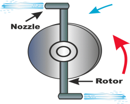
Fig 18
In a reaction turbine, nozzles will move on bearing in the opposite direction of the steam flow and the pressure is not constant in this turbine. That's why; a reaction force is always applied on the nozzles and tubes. In this turbine steam produces both impulsive and reactive force. So, the resultant force produces to the rotor is the vector sum of impulsive and reactive force and the reaction force is an unbalanced condition. Generally, this turbine is not used for commercial purpose. Due to this reactive force, it is called reaction turbine.
An example of this turbine is Parson's Turbine
The single-stage impulse turbine is also called the de Laval turbine after its inventor. The turbine consists of a single rotor to which impulse blades are attached. The steam is fed through one or several convergent-divergent nozzles which do not extend completely around the circumference of the rotor, so that only part of the blades is impinged upon by the steam at any one time. The nozzles also allow governing of the turbine by shutting off one or more them.
The velocity diagram for a single-stage impulse has been shown in Fig. 19. Figure 20 shows the velocity diagram indicating the flow through the turbine blades.
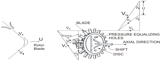
Figure 19 Schematic diagram of an Impulse Turbine
V1 andV2 = Inlet and outlet absolute velocity
Vr1 andVr2= Inlet and outlet relative velocity (Velocity relative to the rotor blades.)
U = mean blade speed
α1= nozzle angle, α2= absolute fluid angle at outlet
It is to be mentioned that all angles are with respect to the tangential velocity ( in the direction of U )
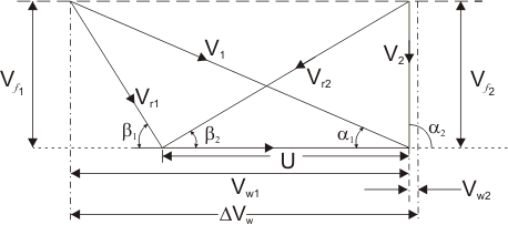
Figure 20 Velocity diagram of an Impulse Turbine
β1 and β2 = Inlet and outlet blade angles
Vw1 and Vw2 = Tangential or whirl component of absolute velocity at inlet and outlet
Vf1 and Vf2 = Axial component of velocity at inlet and outlet
Tangential force on a blade Fu = ṁ(Vw1 - Vw2 ) (mass flow rate X change in velocity in tangential direction)
or, Fu = ṁ∆ Vw
Power developed = ṁ .U.∆ Vw
Blade efficiency or Diagram efficiency or Utilization factor is given by
 Work done/K.E supplied
or,

Stage efficiency 


Optimum blade speed of a single stage turbine


Where,  = friction coefficient

ρ=U/V1 = Blade speed / Fluid velocity at the blade inlet = Blade speed ratio
 is maximum when
  also
also 
Or 
Or 
α1 is of the order of 180 to 220
Now,  (For single stage impulse turbine)
 The maximum value of blade efficiency


For equiangular blades,
If the friction over blade surface is neglected
Reaction turbine
Reaction turbine is one that is constructed of rows of fixed and rows of moving blades. The fixed blades act as nozzles. The moving blades move as a result of the impulse of steam received (caused by change in momentum) and also as a result of expansion and acceleration of the steam relative to them. In other words, they also act as nozzles. The enthalpy drop per stage of one row fixed and one row moving blades is divided among them, often equally. Thus a blade with a 50 percent degree of reaction, or a 50 percent reaction stage, is one in which half the enthalpy drop of the stage occurs in the fixed blades and half in the moving blades. The pressure drops will not be equal, however. They are greater for the fixed blades and greater for the high-pressure than the low-pressure stages.
The moving blades of a reaction turbine are easily distinguishable from those of an impulse turbine in that they are not symmetrical and, because they act partly as nozzles, have a shape similar to that of the fixed blades, although curved in the opposite direction. The schematic pressure line (Fig. 21) shows that pressure continuously drops through all rows of blades, fixed and moving. The absolute steam velocity changes within each stage as shown and repeats from stage to stage. Figure 24.3 shows a typical velocity diagram for the reaction stage.
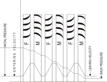
Figure 21 Three stages of reaction turbine indicating pressure and velocity distribution
Pressure and enthalpy drop both in the fixed blade or stator and in the moving blade or Rotor
Degree of reaction = Enthalpy drop in rotor / Enthalpy drop in stage
Or R = h1 – h2 / h0 – h1
A very widely used design has half degree of reaction or 50% reaction and this is known as Parson's Turbine. This consists of symmetrical stator and rotor blades.
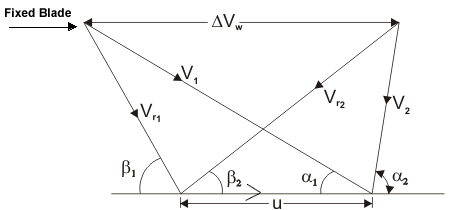
Figure 22 The velocity diagram of reaction blading
The velocity triangles are symmetrical and we have
α1 = β2, β1 = α2
Energy input per stage (unit mass flow per second)


From the inlet velocity triangle we have,

Work done (for unit mass flow per second)  = W = U∆VW

Therefore, the Blade efficiency
Put ρ = U / V1 then

For the maximum efficiency  and we get


From which finally it yields

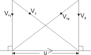
Figure 23 Velocity diagram for maximum efficiency
Absolute velocity of the outlet at this stage is axial (see figure 25.1). In this case, the energy transfer
E = U∆VW = U2
 can be found out by putting the value of ρ= cosα1 in the expression for blade efficiency


 is greater in reaction turbine. Energy input per stage is less, so there are more number of stages.
Key points
1) Degree of reaction = Enthalpy drop in rotor / Enthalpy drop in stage
2) Blade efficiency -
Losses in steam turbines
We know an ideal machine which has 100% gross efficiency will do the equivalent work to the isentropic enthalpy. It means turbine uses every single bit of heat drop produced by steam. But practically turbine's work done is much less than isentropic heat drop of the steam used. Because some internal losses occurred at the time of its operation. These losses are directly affected by the turbines output as well as its efficiency. Practically 100% gross efficiency is not possible for any turbine. When turbine works, some factors have reduced the output of the turbine, known as the losses in steam turbine or internal loss in the turbine. But this loss can be minimized through some process. Though there are several losses in a turbine.
1. Nozzle Friction Loss:-
It is a very important loss for Impulse Turbine. When steam passes through the nozzles, friction loss occurs and the formation of eddies. Friction occurs in the nozzle due to the factor of nozzle efficiency and it is the ratio of actual enthalpy drop to isentropic enthalpy drop.
2. Blade Friction Loss:-
This loss is important for both Impulse and Reaction turbine. Blade friction loss is due to the steam's gliding over the blades and friction of the surface of the blades. The effect of turbine blades is considered as a blade velocity coefficient. The relative velocity of steam is reduced for this loss.
3. Wheel Friction Loss:-
When steam passes through the rotating turbine wheel, it produces some resistance on the turbine wheel. As a result, it rotates in lower speed from its original speed. It is the loss in both Impulse and Reaction turbine. The total frictional loss is about 10% of total turbine loss.
4. Losses due to mechanical friction:-
This loss is for turbine's bearing. Mechanical friction loss is due to the friction between the shaft and wheel bearing and also the regulating valve of the turbine. This loss may be reduced by proper lubrication of the moving parts of the turbine. This loss occurs both Impulse and Reaction turbine.
5. Losses due to leakage:-Leakage loss is different in both Impulse and reaction turbine. In Impulse turbine, leakage loss occurs between the shaft, bearings, nozzles and stationary diaphragms. For Reaction turbine, it may occur at the blade tips. This loss is due to the leakage of steam on each stage of the turbine. Total leakage loss is about 1 to 2% of total turbine loss.
6. Residual Velocity loss:-
When kinetic energy of steam leaves from the turbine wheel, it happens. Actually, steam leaves from the turbine with some certain absolute velocity. That's why steam loses some kinetic energy. Residual velocity loss can be reduced by multistage turbines. This loss is about 10 to 12% in a single stage turbine.
7. Loss in regulating valves:-
Before entering the steam to the turbine, it passes through the boilers stop and regulating valve. Steam gets throttled in these regulating valves and as a result steam pressure will be less than the boiler pressure at the entry of turbine.
Steam turbine governing system is a method, used to maintain a constant steady speed of turbine. The importance of this method is, the turbine can maintain a constant steady speed irrespective of variation of its load. A turbine governor is provided for this arrangement. The purpose of the governor is to supply steam into the turbine in such a way that the turbine gives a constant speed as far as possible under varying the load. So, basically Steam turbine governing system is a process where turbine maintains a steady output speed irrespective of variation of load. The different types of steam turbine governor of are:
1. Throttle Governing Of Steam Turbine
2. Nozzle Control Governing Of Steam Turbine
3. Bypass Governing Of Steam Turbine
1. Throttle Governing Of Steam Turbine:-
Throttle Governing of steam Turbine is most popular and easiest way to control the turbine speed. When steam turbine controls its output speed by varying the quantity of steam entering the turbine is called Throttle Governing. It is also known as Servomotor methods.
In this system, a centrifugal governor is driven from the main shaft of turbine by belt or gear arrangement. A control valve is used to control the direction of oil flow which supplied by the pipe AA or BB. The servomotor or relay valve has a piston which moves towards left or right depending upon the pressure of oil flow through the pipes AA or BB. This cylinder has connected a needle which moves inside the nozzle.When the turbine is running at normal speed, everything in the turbine such as such control valve, servomotor, piston position, fly balls of centrifugal governor will be in their normal position as shown in the figure. The mouth of both pipes AA or BB is closed into the control valves.
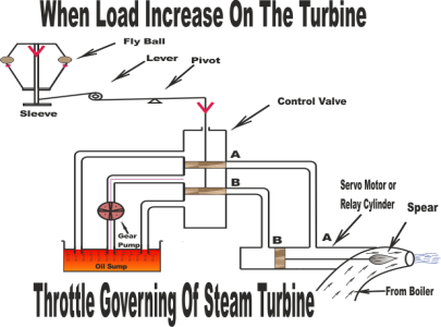
Fig 23
Assume that the turbine's load increases. It will decrease its speed which will decrease the centrifugal force of the turbine. Now fly balls of the governor will come down thus decreasing their amplitude. These fly balls also bring down the sleeve. The sleeve is connected to a control valve rod through a lever pivoted on the fulcrum. This down word sleeve will raise the control valve rod. Now oil is coming from the from the oil sump, pumped by gear pump is just stay at the mounts of both pipes AA or BB which are closed by the two wings of control valves. So, raise of control valve rod will open the mouth of the pipe AA but BB is still closed. Now the oil pressure is coming from the pipe AA. This will rush from the control valve which will move the right side of the piston. As a result, the steams flow rate into the turbine increases which will bring the speed of the turbine to the normal range. When speed of the turbine will come to its normal range, fly balls will come into its normal position. Now, sleeve and control valve rod will back to its normal position.
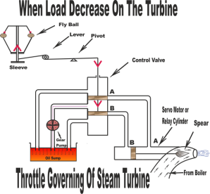
Fig 24
2. Nozzle Control Governing Of Steam Turbine:-
It is another interesting method by which turbine's speed can be controlled. Nozzle control governing of steam turbine is basically used for part load condition. Some set of nozzles are grouped together (may be two, three or more groups) and each group of the nozzle is supplied steam controlled by valves. Every valve is closed by the corresponding set of nozzle. Steam's flow rate is also controlled by these nozzles. Actually, nozzle control governing is restricted to the first stage of turbine whereas the subsequent nozzle area in other stage remains constant. According to the load demand, some nozzles are in active and other inactive position. Suppose turbine holds ten numbers of nozzles. If the load demand is reduced by 50% then five numbers of nozzles are in open condition and rest is closed. This method is suitable for SIMPLE IMPULSE TURBINE. It is a process where rate of steam flow is regulated depending on the opening and closing of set of nozzles rather than regulating its pressure.
3. Bypass Governing Of Steam Turbine:-
Bypass governing of steam turbineis a method where a bypass line is provided for the steam. Especially this is used when turbine is running in overloaded condition. The bypass line is provided for passing the steam from first stage nozzle box into a later stage where work output increase. This bypass steam is automatically regulated by the lift of valve which is under the control of the speed of the governor for all loads within its range. Bypass valve is open to release the fresh stem into the later stage of the turbine. In the later stage output, work is increased and the efficiency is low due to the throttle effect.
Comparison of Steam Turbine over Steam Engines:
(a) The thermal efficiency of a steam turbine plant is higher.
(b) Steam turbines are highly simplified in construction and operation.
(c) Condensate can be directly used in boilers.
(d) Vibration and noise are minimized.
(e) Balancing of rotor can be done accurately.
(f) Much higher speed is possible.
(g) Steam turbines are suitable for the operation with high-pressure steam.
(h) They are well suited for large steam power plants.
Key points
1) When steam turbine controls its output speed by varying the quantity of steam entering the turbine is called Throttle Governing. It is also known as Servomotor methods.
2) Steam turbines are suitable for the operation with high-pressure steam.
Reference
1) Engineering thermodynamics P.K nag
2) I.C engineering =m.l mathur
3) https://www.physicsforums.com/attachments/flow-calculations-pdf.20219/