UNIT 3
Centroid and moment of inertia
Centroid and moment of inertia:
A body of mass m in equilibrium under the action of tension in the cord, and resultant W of the gravitational forces acting on all particles of the body.
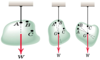
As long as dimensions of the body are smaller compared with those of the earth
We assume uniform and parallel force field due to the gravitational attraction of
The earth. The unique Point G is called the Centre of Gravity of the body (CG).
Determination of CG
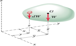
Moment of resultant gravitational force W about any axis equals the sum of the moments about the same axis of the gravitational forces dW acting on all particles treated as infinitesimal elements.
Weight of the body W = ∫dW
Moment of weight of an element (dW) @ x-axis = ydW
Sum of moments for all elements of body = ∫ydW
From Principle of Moments: ∫ydW = ӯ W
Numerator of these expressions represents the sum of the moments;
Product of W and corresponding coordinate of G represents the moment of the sum Moment Principle.

Determination of CG 
Substituting W = mg and dW = gdm

In vector notations:
Position vector for elemental mass: r = xi + yj + zk
Position vector for mass center G: 

Density ρ of a body = mass per unit volume
Mass of a differential element of volume dV to dm = ρdV
ρ may not be constant throughout the body.

Center of Mass: Following equations independent of g
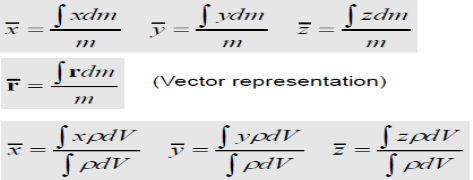
Unique point [= f(ρ)] :: Centre of Mass (CM)
Symmetry
CM always lie on a line or a plane of symmetry in a homogeneous body.
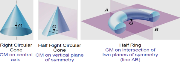
Centroid

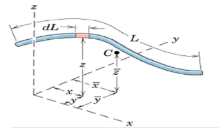
Lines: Slender rod, Wire Cross-sectional area = A ρ and A are constant over L
dm = ρAdL
Centroid and CM are the same points.

Areas: Body with small but constant thickness t
Cross-sectional area = A
ρ and A are constant over A
dm = ρtdA
Centroid and CM are the same points

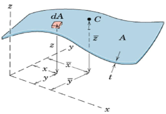

Numerator = First moments of Area
Volumes: Body with volume V
ρ constant over V
dm = ρdV
Centroid and CM are the same point, (Numerator = First moments of Volume)
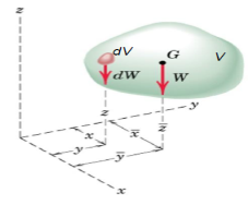
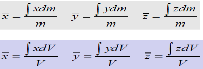
Centroids of Lines, Areas, and Volumes
1. Order of Element Selected for Integration
2. Continuity
3. Discarding Higher Order Terms
4. Choice of Coordinates
5. Centroidal Coordinate of Differential Elements
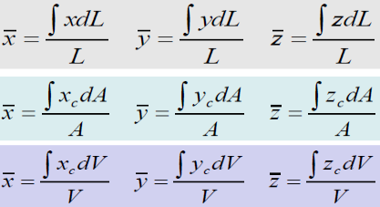
Composite Bodies and Figures
Divide bodies or figures into several parts such that their mass centres can be conveniently determined Use Principle of Moment for all finite elements of the body.

Irregular area: Integration vs Approximate Summation
= (hΔx)yc and (hΔx)xc
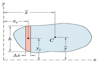

Reduce the problem to one of locating the centroid of area.
Approximate summation instead of integration Divide the area into several strips
Volume of each strip = AΔx
Plot all such A against x.
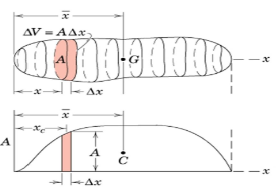
Area under the plotted curve represents volume of whole body and the x-coordinate of the centroid of the area under the curve is given by:

Accuracy may be improved by reducing the width of the strip
When a distributed loading whose intensity varies linearly acts perpendicular to an area, the computation of the moment of the loading distribution about an axis involves a quantity called the moment of inertia of the area or simply area moment of inertia.
Consider a differential plate, subjected to fluid pressure P that varies linearly with depth, as shown in fig, such that  , where,
  is the specific weight of fluid.
The force acting on a acting on the differential area of the plate is given by

The moment of this this force about the x-axis is

Integrating  over the entire area of the plate yields


The integral part of the moment equation is called area moment of inertia about x-axis 

Similarly, area moment of inertia about y-axis is given as,

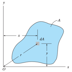
Moment of Inertia for area can also be given as

Where, A is the total area
And k is referred as radius of gyration
Radius of gyration for area of a plate about an axis is defined as the radial distance to a point which would have a same moment of inertia as the plate’s actual distribution of area, if the total area of the plate were concentrated.
It is given by,

Parallel axis theorem states that
The moment of inertia of a body about an axis parallel to the body passing through its centre is equal to the sum of moment of inertia of body about the axis passing through the centre and product of mass of the body times the square of distance between the two axes.
Parallel axis theorem statement can be expressed as follows:
I = Ic + Mh2
Where,
Parallel Axis Theorem Derivation
Let Ic be the moment of inertia of an axis which is passing through the center of mass (AB from the figure) and I be the moment of inertia about the axis A’B’ at a distance of h.
Consider a particle of mass m at a distance r from the center of gravity of the body.
Then,
Distance from A’B’ = r + h
I = ∑m (r + h)2
I = ∑m (r2 + h2 + 2rh)
I = ∑mr2 + ∑mh2 + ∑2rh
I = Ic + h2∑m + 2h∑mr
I = Ic + Mh2 + 0
I = Ic + Mh2
Hence, the above is the formula of parallel axis theorem.
It states that , if  be the moments of inertia of figure or plane section about two axis x and y which are perpendicular to each other at point O, then moment of Inertia of that plane section about Z axis which is perpendicular to the plane [&(
 is given by :

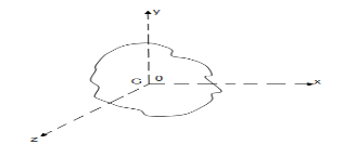
 of plane area about Z axis passing through C.G.
 of plane area about X axis passing through C.G
 of plane area about Y axis passing through C.G
 Is also called as polar moment of Inertia (J)
For a general three-dimensional body, it is always possible to find 3 mutually orthogonal axis (an x, y, z coordinate system) for which the products of inertia are zero, and the inertia matrix takes a diagonal form. In most problems, this would be the preferred system in which to formulate a problem. For a rotation about only one of these axis, the angular momentum vector is parallel to the angular velocity vector. For symmetric bodies, it may be obvious which axis is principle axis. However, for an irregular-shaped body this coordinate system may be difficult to determine by inspection; we will present a general method to determine these axes in the next section. But, if the body has symmetries with respect to some of the axis, then some of the products of inertia become zero and we can identify the principal axes.
For instance, if the body is symmetric with respect to the plane 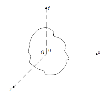 then, we will have
  and
and  will be a principal axis. This can be shown by looking at the definition of the products of inertia.

The integral for, say, 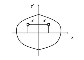 can be decomposed into two integrals for the two halves of the body at either side of the plane
  . The integrand on one half
  will be equal in magnitude and opposite in sign to the integrand on the other half (because
  will change sign). Therefore, the integrals over the two halves will cancel each other and the product of inertia
  will be zero. (As will the product of inertia
  ) Also, if the body is symmetric with respect to two planes passing through the center of mass which are orthogonal to the coordinate axis, then the tensor of inertia is diagonal, with

Another case of practical importance is when we consider axisymmetric bodies of revolution. In this case, if one of the axis coincides with the axis of symmetry, the tensor of inertia has a simple diagonal form. For an axisymmetric body, the moments of inertia about the two axis in the plane will be equal. Therefore, the moment about any axis in this plane is equal to one of these. And therefore, any axis in the plane is a principal axis. One can extend this to show that if the moment of inertia is equal about two axis in the plane (IP P = Ixx), whether or not they are orthogonal, then all axes in the plane are principal axes and the moment of inertia is the same about all of them. In its inertial properties, the body behaves like a circular cylinder.
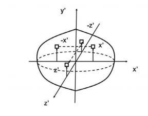
The tensor of inertia will take different forms when expressed in different axes. When the axes are such that the tensor of inertia is diagonal, then these axes are called the principal axes of inertia.
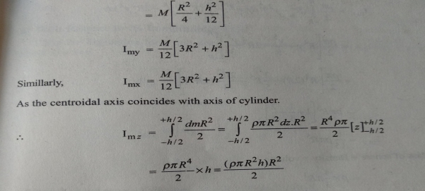
The moment of inertia of cylinder about a perpendicular axis passing through its centre is determined by;
Ix = ¼ MR2 + 1/12 ML2
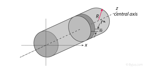
We will look at the derivation of this formula below.
Generally, the derivation involves 3 primary steps. It includes;
1. Cutting the cylinder into infinitesimally thin disks
We will consider the cylinder having mass M, radius R, length L and the z-axis which passes through the central axis.
Here,
Density ρ = M / V
Next, we will consider the moment of inertia of the infinitesimally thin disks with thickness dz.
First, we assume that dm is the mass of each disk, We get;
dm = ρ X Volume of disk
dm = M / V X (πr2.dz)
We take V = area of circular face X length which is = πr2L. Now we obtain;
dm = M / πr2L X (πr2.dz)
dm = M / L X dz
The moment of inertia about the central axis is given as;
dlz = ½ dmR2
Use of Perpendicular Axis Theorem
We now apply the perpendicular axis theorem which gives us;
dlz = dlx + dly
Here, if we need to consider that both x and y moments of inertia are equal by symmetry.
dlx = dly
We need to combine the equations for the perpendicular axis theorem and symmetry. We get;
dlx = dlz / 2
Now we substitute lz from the equation above.
dlx = ½ x ½ dmR2
dlx = ¼ dmR2
Alternatively, for the x-axis, we use the parallel axis theorem to find the moment of inertia. We get;
dlx = ¼ dmR2 + dmz2
Integration
Now we conduct integration over the length of the cylinder to express the mass element dm in terms of z. We take the integral from z=0 to z=L.
Ix = o∫L dlx
Ix = o∫L ¼ dzR2 + o∫L ¼ z2 m / l dz
Ix = ¼ M / L R2z + M / L Z3 / 3]0L
Since it is a definite form of integral we ignore the constant. We will now have;
Ix = ¼ M / L R2 L + M / 3L 2L3 / 23
Ix = ¼ MR2 + 1/12 ML2
Therefore, I =1/2 MR2
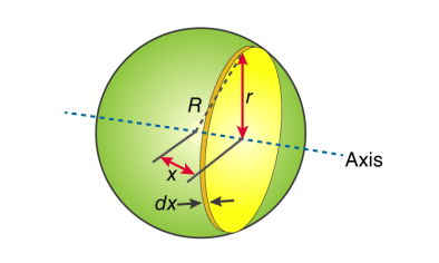
First, we take the moment of inertia of a disc that is thin. It is given as;
I = ½ MR2
In this case, we write it as;
dI (infinitesimally moment of inertia element) = ½ r2dm
Find the dm and dv using;
dm = p dV
p = moment of a thin disk of mass dm
dv = expressing mass dm in terms of density and volume
dV = π r2 dx
Now we replace dV into dm. We get;
dm = p π r2 dx
And finally, we replace dm with dI.
dI = ½ p π r4 dx
The next step involves adding x to the equation. If we look at the diagram we see that r, R and x forms a triangle. Now we will use Pythagoras theorem which gives us;
r2 = R2 – x2
Now if we substitute the values we get;
dI = ½ p π (R2 – x2)2 dx
This leads to:
I = ½ p π -R∫R (R2 – x2)2 dx
After integration and expanding we get;
I = pπ 8/15 R5
Additionally, we have to find the density as well. For that we use;
P (density) = M (mass) / V (volume)
p = M (mass) / (4/3 πR3)
If we substitute all the values;
I = 8/15 π [M / (4/3 πR3)] R5
I = ⅖ MR2
Moment of inertia of Solid Cone
We will take a solid cone where its axis will pass through the centre with radius = r, height = h. We will need to determine the mass though.
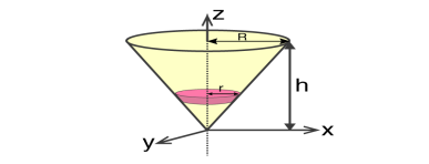
We take the elemental disc whose mass is given by;
dm = ρ ⋅ π r2dz
Density is given as;
ρ = M / V = M / (⅓ π R2h)
With this, we will calculate the dm.
dm = [M / (⅓ π R2h)] X π r2dz
dm = (3M / R2h) X r2 dz
If we consider the similarity of the triangle, then we have;
R / r = h / z
r = R .z / h
Now,
dm = (3M / R2h )⋅( R2 / h2) ⋅ z2dz
dm = (3M / h3 ). z2dz
If we consider z-axis, the moment of inertia of the elemental disk will be;
dI = ½ dmr2
dI = ½ ⋅ (3M / h3 ) . z2 ⋅ (z2 R2 / h2) dz
dI = 3 / 2 ⋅ M R2 / h5 X z4dz
Now we will follow the integration process. Here;
I = 3 / 2 ⋅ M R2 / h5 o∫h z4dz
I = 3 / 2 ⋅ M R2 / h5 [z5 / 5 ]oh
I = 3 / 2 ⋅ M R2 / h5 ⋅ h5 / 5
Therefore, I = 3/10 MR2
References:
1. Beer, F.P and Johnston Jr. E.R., “Vector Mechanics for Engineers (In SI Units): Statics and Dynamics”, 8th Edition, Tata McGraw-Hill Publishing company, New Delhi (2004).
2. Vela Murali, “Engineering Mechanics”, Oxford University Press (2010).
3. A Textbook of Engineering Mechanics, R.K. Bansal, Laxmi Publications.
4. Engineering Mechanics, R.S. Khurmi, S.Chand Publishing.
5. Meriam J.L. and Kraige L.G., “Engineering Mechanics- Statics - Volume 1, Dynamics- Volume 2”, Third Edition, John Wiley & Sons (1993).
6. Rajasekaran S and Sankarasubramanian G., “Engineering Mechanics Statics and Dynamics”, 3 rd Edition, Vikas Publishing House Pvt. Ltd., (2005).
7. Bhavikatti, S.S, and Rajashekarappa, K.G., “Engineering Mechanics”, New Age International (P) Limited Publishers, (1998).
8. Engineering mechanics by Irving H. Shames, Prentice-Hall.
