UNIT 4
Kinematics of a rigid body and Kinetics of a rigid body
Kinematics of a rigid body:
A rigid body is an idealization of a solid body where the deformations occurring on the body are neglected. In other words, the distance between any two given points of a rigid body remains a constant regardless of the external force acting upon it.
The concept of a rigid body and rigid body dynamics was developed to solve a range of problems that could not be explained with classical physics. Motions such as rotation of a fan, a potter’s wheel, a top, etc cannot be adequately explained with a point mass. In real life, in the case of bodies such as wheels and steel rods, deformation, or bending is considered to be negligible, and we treat them as rigid.
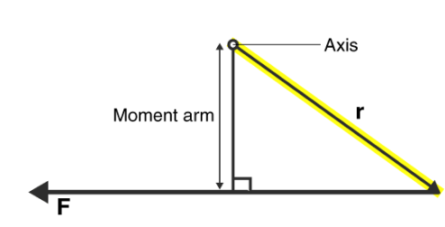
The question is, what kind of motion can a rigid body have? This new outlook meant that there now could be two different types of rigid body motion. We could explore and understand more kinds of problems and in doing so develop a deeper understanding of the world around us. A rigid Body Dynamics laid the foundation to what has come after, Quantum Mechanics. The two types of motion a rigid body can undergo are;
Configuration Space for a rigid body:
A macroscopic body is made up of a very large number of atoms. Describing the motion of such a system without some simplifications is clearly impossible. Many objects of interest, however, are very well approximated by the assumption that the distances between the atoms in the body are fixed. This constitutes a set of holonomic constraints, but not independent ones, as we have here 12n(n−1) constraints on 3n coordinates.
Rather than trying to solve the constraints, we can understand what are the generalized coordinates by recognizing that the possible motions which leave the interparticle lengths fixed are combinations of translations of the body as a whole, r⃗ α→r⃗ α+C⃗ and rotations of the body about some fixed, or “marked”, point.
We will need to discuss how to represent the latter part of the configuration, (including what a rotation is), and how to re-express the kinetic and potential energies in terms of this configuration space and its velocities.
The first part of the configuration, describing the translation, can be specified by giving the coordinates of the marked point fixed in the body, R~(t). Often, but not always, we will choose this marked point to be the center of mass R⃗ (t) of the body.
In order to discuss other points that are part of the body, we will use an orthonormal coordinate system fixed in the body, known as the body coordinates, with the origin at the fixed point R~.
The constraints mean that the position of each particle of the body has fixed coordinates in terms of this coordinate system. Thus, the dynamical configuration of the body is completely specified by giving the orientation of these coordinate axes in addition to R~. This orientation needs to be described relative to a fixed inertial coordinate system, or inertial coordinates, with an orthonormal basis ei.
Stay tuned with BYJU’S to learn more about A rigid Body Dynamics, Translational Motion and Rotational Motion, and much more with interesting video lectures.
Just by using our intuition, we can begin to see how rotational quantities like θ, ω, and α are related to one another. For example, if a motorcycle wheel has a large angular acceleration for a fairly long time, it ends up spinning rapidly and rotates through many revolutions. In more technical terms, if the wheel’s angular acceleration α is large for a long period of time t, then the final angular velocity ω and angle of rotation θ are large. The wheel’s rotational motion is exactly analogous to the fact that the motorcycle’s large translational acceleration produces a large final velocity, and the distance traveled will also be large.
Kinematics is the description of motion. The kinematics of rotational motion describes the relationships among rotation angle, angular velocity, angular acceleration, and time. Let us start by finding an equation relating to ω, α, and t. To determine this equation, we recall a familiar kinematic equation for translational, or straight-line, motion:
v=v0+at
(Constant a)
Note that in rotational motion a = at, and we shall use the symbol a for tangential or linear acceleration from now on. As in linear kinematics, we assume a is constant, which means that angular acceleration α is also a constant because
a = rα. Now, let us substitute v = rω and a = rα into the linear equation above:
rω = rω0 + rat.
The radius r cancels in the equation, yielding
ω = ω0 + at. (Constant a)
Where ω0 is the initial angular velocity. This last equation is a kinematic relationship among ω, α, and t —that is, it describes their relationship without reference to forces or masses that may affect rotation. It is also precisely analogous in form to its translational counterpart.
Starting with the four kinematic equations we developed in One-Dimensional Kinematics, we can derive the following four rotational kinematic equations (presented together with their translational counterparts): In these equations, the subscript 0 denotes initial values (θ0, x0, and t0 are initial values), and the average angular velocity ω¯ and average velocity v¯ are defined as follows: ω=ω0+ω2 and v=v0+v2
| ||
| ||
| ||
Relative velocity is used to denote the aircraft moving in the wind or boats moving through the water, etc. The velocity is measured within the object according to the observer. It can be measured using the use of an intermediate reference frame.
In simpler terms, this can be the vector sum of the velocities. The relative velocity formula is expressed as
Where
VAB is the velocity with respect to And B, VBC is the velocity with respect to B and C and VAC is the velocity with respect to And C.
The velocity of an object A relative to another object B is the velocity that objects A would appear to have to an observer moving with B.
Have you ever been sat in a stationary train at a station, and seen another train moving off forwards? Did you feel you were moving backward even though you knew you were stationary?
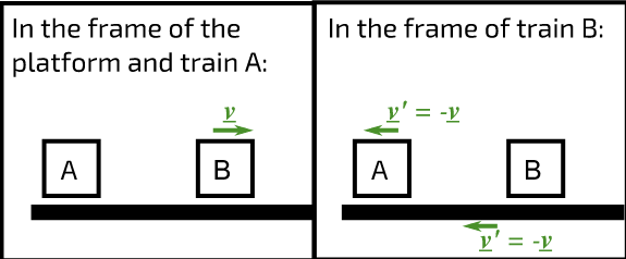
To you, sitting on the stationary train (A), or to a person on the platform, the moving train (B) appears to be traveling at a velocity v away. However, to a person on the moving train, the platform and the stationary train at the platform both appear to be moving in the opposite direction with the same speed or to put it another way, with the opposite velocity. Really what we are measuring in all of these cases is the velocity relative to an observer.

Figure 1: Relative velocities of trains And B and the platform
Kinetics of a rigid body:
Force [(F) or ( P )] :-
It is an external agency that produces or tends to produce, destroy, or tends to destroy motion.
OR
It is an external agent that changes or tends to change the state of motion of the body.
It is a vector quantity.
Force is also known as the rate of change of momentum.
As momentum = mass x velocity
But mass will never change, then
Force = mass x rate of change of velocity
= mass x Acceleration
F = P = ma
S.I. Unit: - Newton (N)
KiloNewton (KN) = 103 N
MegaNewton (MN) = 106 N
GigaNewton (GN) = 103 N
TeraNewton (TN) = 1012 N
1 Kg Force:-
The force required producing unit gravitational acceleration on unit mass.
01 kg force = mass x Acceleration (gravity)
= 1 kg x 9.81 m / s2
= 9.81 kg.m / s2
1 kg.F = 9.81 Kg m / s2
1 kg.F = 9.81 N
i.e. 1 Kg = 9.81 N
Characteristics of Force:-
1>. Magnitude:- The value of force i.e. 10N, 2KN, etc.
2>. Direction:- Line of action & angle formed with the fixed axis.
3>. Nature of force or sense:-It means whether the force is push or pull.


Pull type force Push type force
Push:- Force acting towards the point
Pull: - Force acting away from the point.
4>. Point of application:-
The point at which or through which the force acts.
Effects of Force:-
Force may produce the following effects on the body.
1>. It may change the state of the body.
i.e. if the body is at rest, force may bring it in motion or if the body is in motion, force may accelerate it or force may stop it or may retard it.
2>. It may produce internal stress in the body.
3>. It may produce deformation in non-a rigid body.
4>. It may produce a rotational effect in the body.
5>. It may keep the body in a stable state (Equilibrium).
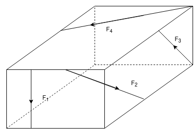
When a single agency is acting on the body then it is known as force. But when numbers of forces are acting on the body simultaneously, then it is known “System of force”.
Types of Force System
1. Co-planer Forces
2. Non-Co-planer Forces
3. Co-linear Forces
4. Non-Co-linear Forces
5. Concurrent Forces
6. Non-Concurrent Forces
7. Parallel Forces (Like & unlike)
8. Coplanar Concurrent Forces
9. Coplanar non-concurrent Forces
10. Non-Coplanar Concurrent Forces
11. Non-Coplanar Non-Concurrent Forces
1. Co – planer Force System / Forces:-
The forces whose line of action lies on the same plane are called Co-planer Forces.

The forces which are acting in the same plane are known as co-planer forces.
2. Non-Co-planer Force System / Forces:-
- Forces whose line of action does not lie in the same plane ( i.e. lie in different planes )
- Forces that are acting in the different planes known as non-co-planer forces (system).
3. Co-linear force system / Forces:-
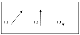
- The forces whose line of action lies on the same line are called co-linear forces.
- The forces which are acting along the same straight line are called co-linear forces.
4. Non – Collinear Forces/force system:-
- The forces which are not acting along the same straight line are known as non-co-linear forces.
- The forces whose line of action doesn’t lie on the same line.
5. Concurrent forces / Force system:-
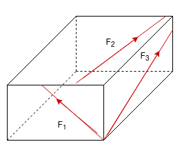
- The forces whose line of action meets at one common point are called concurrent forces.
- The forces which are passing through a common point are concurrent forces.
- The forces which meet at one point are concurrent forces.
6. Non Concurrent force system/forces:-
- The forces which are not passing through common point OR
- The forces whose line of action does not meet at common point OR
- The force which does not meet at one point is called as non-concurrent forces.

7. Parallel Forces / Force system:-
The forces whose lines of action are parallel to each other are called parallel forces.
a) Like parallel Forces:-
The forces whose lines of actions are parallel to each other and having the same direction are called like parallel forces.
Forces that are parallel to each other & acting in the same direction are called as Like parallel forces.
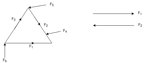
b. Unlike parallel Forces:-
The forces which are parallel to each other but having different directions or The forces which are parallel to each other & acting in opposite direction are called unlike parallel forces.

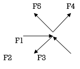
8. Coplanar concurrent forces:-
The forces which meet at one point & their lines of action also lie on the same plane are called a coplanar concurrent force system.

9. Coplanar non-concurrent forces:-
The forces which do not meet at one point but their line of action lies on the same plane are known as the coplanar non-concurrent system of force.
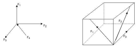
10. Non-Coplanar concurrent forces:-
The forces which meet at one point but their line of action do not lie on the same plane are known as non-coplanar concurrent forces.
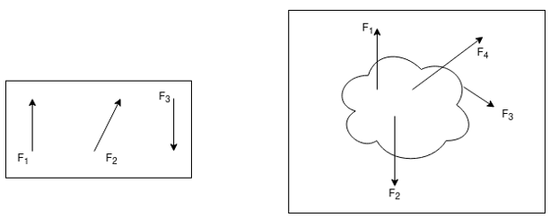
11. Non-coplanar non-concurrent forces:-
Their forces that do not meet at one point & their lines of actions do not lie on the same plane are called non - coplanar non-concurrent forces.
It is summarized by the equation: Force (N) = mass (kg) × acceleration (m/s²). Thus, an object of constant mass accelerates in proportion to the force applied. If the same force is applied to two objects of different mass, the heavier object has less acceleration than the lighter object.
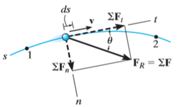
The principle of work and energy states that the sum of the work done by all the forces acting on the particle is equal to the change in total energy (kinetic energy) of the particle.
Consider the particle located on the path that is defined relative to an inertial coordinate system as shown in the figure below.
Let the particle has an initial position  with speed
  and final position
  with speed
Let the particle has a mass m and is subjected to a system of external forces which is represented by the resultant force given below

The equation of motion for the particle in the tangential direction is given by

Applying the kinematic equation  and integrating both sides


Where  and
and  are the initial and final kinetic energies of the particle. Kinetic energy is always positive.
The kinetic energy of an object is the energy associated with the object which is under motion. It is defined as “the energy required by a body to accelerate from rest to stated velocity.” It is a vector quantity.
Mathematically expressed as-
K.E=1/2mv2
Where,
m is the mass of the object measured in kg.
v is the velocity of the object measured in m/s
Kinetic Energy unit
The SI Unit of Kinetic Energy is Joules.
Using kinematics, the equation of motion for a particle of m is given by,


Integrating the above equation between limits  at
at  to
to  at
at 

The term  is referred to as the linear impulse, while the term
  is a change in linear momentum.
Since m is a positive scalar, the linear-momentum vector has the same direction as v.
Linear impulse is a vector quantity that measures the effect of a force during the time the force acts. As time is a positive scalar quantity, the impulse acts in the same direction as the force.
If the force is variable, the resulting impulse is given by

If the force is constant in magnitude and also in direction, the resulting impulse is given by


Graphically, the magnitude of linear impulse is given by the area under the curve plotted on the force versus time plot.
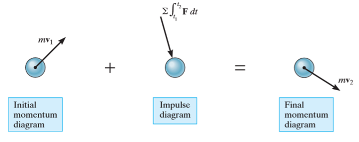
The principle of impulse-momentum states that the sum of all the impulses applied to the particle in a time period of motion of a particle is equal to the change in momentum of the particle.
Mathematically,
Initial momentum + sum of impulses = Final momentum

Momentum
The momentum of an object is the virtue of its mass. It is defined as the product of mass and velocity. It is a vector quantity.
The momentum of a moving object can be mathematically expressed as –
p=mv
Where
Momentum unit
The SI Unit of Momentum is kg.m/s
The relation between Momentum and Kinetic Energy
Kinetic energy and momentum of a moving body can be mathematically related as follows-
Consider the formula of kinetic energy-
K.E=1/2mv2
Multiply and divide R.H.S by m
The above equation gives the relation between Kinetic energy and momentum of the object which is under motion.

The principle of virtual work states that the sum of the incremental virtual works done by all external forces Fi acting in conjunction with virtual displacements _si of the point on which the associated force is acting is zero:

This technique is useful for solving statics problems, with static forces of constraint. A static force of constraint is one that does no work on the system of interest, but merely holds a certain part of the system in place. In a statics problem, there are no accelerations. We can extend the principle of virtual work to dynamics problems, i.e., ones in which real motions and accelerations occur, by introducing the concept of inertial forces. For each parcel of matter in the system with mass m, Newton’s second law states that
F=ma: (1.1.2)
We can make this dynamics problem look like a statics problem by defining an inertial force
F* = - ma (1.1.3)
And rewriting equation (1.1.2) as
F total = F + F* = 0 (1.1.4)
D’Alembert’s principle is just the principle of virtual work with the inertial forces added to the list of forces that do work:


Figure 1.1.1: Sketch of a bead of mass m sliding frictionlessly on a vertical hoop of radius R under the influence of gravity.
Mass falling under gravity
A trivial example would be a mass m falling under the effect of a constant gravitational field g. With z positive upward, the force on the mass is -mg, and the work due to this force under vertical displacement 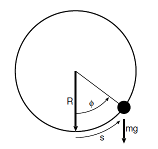
The inertial force is  and the work is
Setting the sum of the two to zero gives us

From which we infer the expected result

D’Alembert’s principle offers no advantages over normal procedures in this case. However, it becomes more economical in problems with constraints.
Bead on the frictionless vertical hoop
Figure 1.1.1 illustrates the slightly more interesting problem of a bead sliding frictionless around a vertically oriented hoop of wire. Here the force of gravity is not in the direction of motion. The component of gravity normal to the hoop does no work on the bead. Nor does the force of the hoop on the bead that constrains the bead to move in a circle. The work on the bead due to gravity for a small displacement  along the wire
The acceleration of the bead also has two components, a radial component
 Where the tangential velocity is
  and a tangential component
The radial component of the inertial force mv2=R does no work. However, the tangential component 
Does: 
D’Alembert’s principle thus gives us


from which we get the governing equation
Books and References:
1. Beer, F.P and Johnston Jr. E.R., “Vector Mechanics for Engineers (In SI Units): Statics and Dynamics”, 8th Edition, Tata McGraw-Hill Publishing company, New Delhi (2004).
2. Vela Murali, “Engineering Mechanics”, Oxford University Press (2010).
3. A Textbook of Engineering Mechanics, R.K. Bansal, Laxmi Publications.
4. Engineering Mechanics, R.S. Khurmi, S.Chand Publishing.
5. Meriam J.L. and Kraige L.G., “Engineering Mechanics- Statics - Volume 1, Dynamics- Volume 2”, Third Edition, John Wiley & Sons (1993).
6. Rajasekaran S and Sankarasubramanian G., “Engineering Mechanics Statics and Dynamics”, 3 rd Edition, Vikas Publishing House Pvt. Ltd., (2005).
7. Bhavikatti, S.S, and Rajashekarappa, K.G., “Engineering Mechanics”, New Age International (P) Limited Publishers, (1998).
8. Engineering mechanics by Irving H. Shames, Prentice-Hall.

