UNIT 5
Simple stress and strain, Pure bending of beams and Torsion
Simple stress and strain:
Normal Stress
Normal stress is a stress that occurs when a member is loaded by an axial force. The value of the normal force for any prismatic section is simply the force divided by the cross-sectional area.
Shear Stress
Normal stress is a result of load applied perpendicular to a member. Shear stress however results when a load is an applied parallel to an area. Looking again at figure one, it can be seen that both bending and shear stresses will develop. Like in bending stress, shear stress will vary across the cross-sectional area.
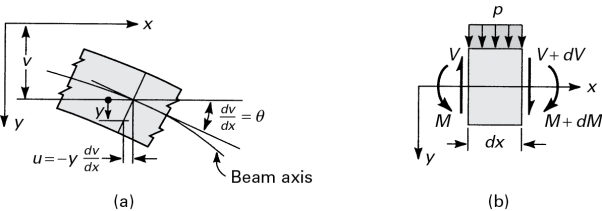
Fig 1
When a beam is bent by transverse loads, usually both a bending moment M and a shear force V act on each cross-section. The distribution of the normal stress associated with the bending moment is given by the flexure formula, Eq. (5.4):
)
Where M and I are taken with respect to the z-axis (fig 1).
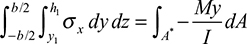
In accordance with the assumptions of elementary bending equations 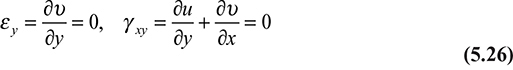
and Equation 
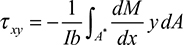
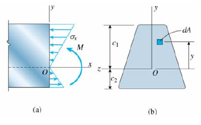
we omit the contribution of the shear strains to beam deformation in these calculations. However, shear stresses do exist, and the shearing forces are the resultant of the stresses. The shearing stress τxy acting at section mn, which is assumed to be uniformly distributed over the area b·dx, can be determined on the basis of equilibrium of forces acting on the shaded part of the beam element (Fig. 5.9). Here b is the width of the beam a distance y1 from the neutral axis, and dx is the length of the element. The distribution of normal stresses produced by M and M + dM is indicated in the figure. The normal force distributed over the left face mr on the shaded area A* is equal to
)
Fig 2 (a) Beam segment for analyzing shear stress (b) cross-section of the beam.
Similarly, an expression for the normal force on the right face ns may be written in terms of M + dM. The equilibrium of x-directed forces acting on the beam element is governed by
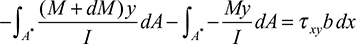
From which we have
After substituting in Equation  we obtain the shear formula (also called the shear stress formula) for beams:
)
The integral represented by Q is the first moment of the shaded area A* with respect to the neutral axis z:
)
By definition,  is the distance from the neutral axis to the centroid of A*. In the case of sections of regular geometry,
  provides a convenient means of calculating Q. The shear force acting across the width of the beam per unit length
)
is called the shear flow.
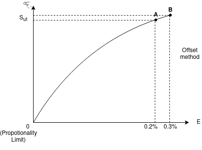
Stress-Strain diagram for Ductile material
Considering low Carbon Steel having a Carbon content less 0.15% and its example is Mild Steel.
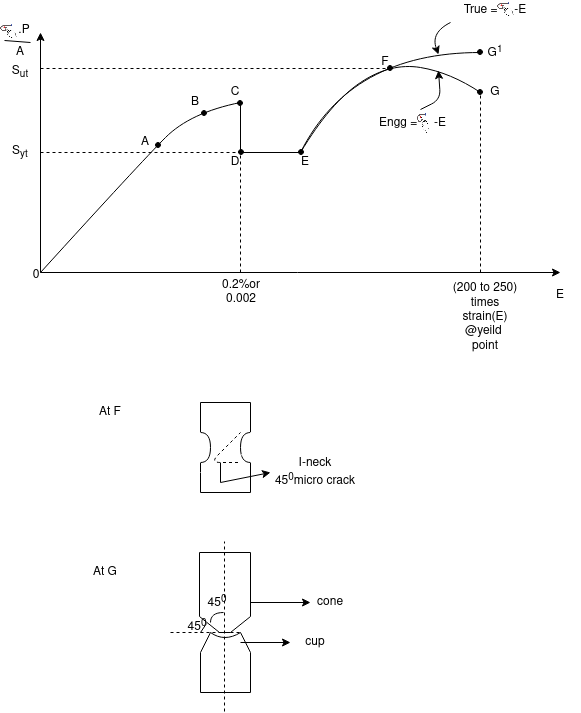
Stress-Strain diagram for Brittle material

OA is non-linear elastic AB is the Strain Hardening.
Different types of stresses and their corresponding strains within elastic limit are related which are referred to as elastic constants. The three types of elastic constants are:
There are three elastic constants;
Young’s Modulus or Modulus of elasticity (E):
It is defined as the ratio of normal stress (σ) to the longitudinal strain (e).
E = (σn) / (e)
Modulus of Rigidity or Shear Modulus (G or C):
It is the ratio between shear stress (τ) and shear strain (es). It is denoted by G or C.
G= τ/es
Bulk Modulus or Volume Modulus of Elasticity (K):
It may be defined as the ratio of normal stress (on each face of a solid cube) to volumetric strain.
It is denoted by K. Bulk modulus is a measure of the resistance of a material to change of volume without change of shape or form.
K = Direct Stress / Volumetric strain
= σ/ev
Strain energy is defined as the energy stored in a body due to deformation. The strain energy per unit volume is known as strain energy density and the area under the stress-strain curve towards the point of deformation. When the applied force is released, the whole system returns to its original shape. It is usually denoted by U.
The strain energy formula is given as,
U = Fδ / 2
Where,
δ = compression,
F = force applied.
When stress σ is proportional to strain ϵ, the strain energy formula is given by,

Where,
σ = stress
 = strain
V = volume of body
Regarding Young’s modulus E, the strain energy formula is given as,
U = σ2 / 2E × V.
Where,
σ = stress,
E = Young’s modulus,
V = volume of the body.
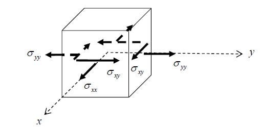
State of plane stress
The state of plane stress is defined as follows:
Plane Stress:
If the stress state at a material particle is such that the only non-zero stress components act in one plane only, the particle is said to be in-plane stress. The axes are usually chosen such that the x y plane is the plane in which the stresses act, Fig.
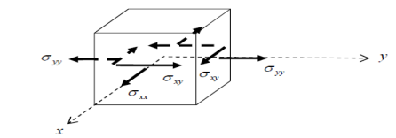
Figure: non-zero stress components acting in the x – y plane
The stress can be expressed in the matrix form
Example
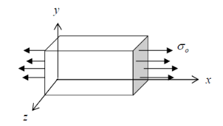
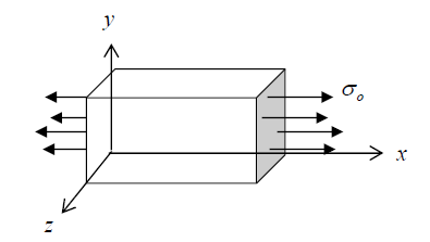
The thick block of uniform material shown in Fig. loaded by a constant stress  in the x-direction, will have
  and all other components zero everywhere. It is therefore in a state of plane stress.
Analysis of Plane Stress
Next are discussed the stress invariants, principal stresses, and maximum shear stresses for the two-dimensional plane state of stress, and tools for evaluating them. These quantities are useful because they tell us the complete state of stress at a point in simple terms. Further, these quantities are directly related to the strength and response of materials. For example, the way in which a material plastically (permanently) deforms is often related to the maximum shear stress, the directions in which flaws/cracks grow in materials are often related to the principal stresses, and the energy stored in materials is often a function of the stress invariants.
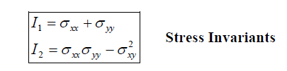
Stress Invariants
Stress invariant is some function of the stress components that is independent of the coordinate system being used; in other words, they have the same value no matter where the x- y axes are drawn through a point. In a two-dimensional space, there are two stress invariants, labeled I1 and I2. These are
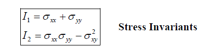
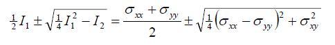
These quantities can be proved to be invariant directly from the stress transformation equations, Eqns. 3.4.9 Physically, invariance of 1 I and 2 I means that they are the same for any chosen perpendicular planes through a material particle. Combinations of the stress invariants are also invariant, for example, the important quantity
Pure bending of beams:
When a beam having an arbitrary cross-section is subjected to a transverse load the beam will bend. In addition to bending the other effects such as twisting and buckling may occur, and to investigate a problem that includes all the combined effects of bending, twisting and buckling could become a complicated one. Thus we are interested to investigate the bending effects alone, in order to do so, we have to put certain constraints on the geometry of the beam and the manner of loading.
Assumptions:
The constraints put on the geometry would form the assumptions:
1. Beam is initially straight and has a constant cross-section.
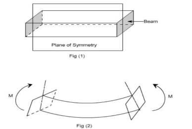
2. Beam is made of homogeneous material and the beam has a longitudinal plane of symmetry.
3. Resultant of the applied loads lies in the plane of symmetry.
4. The geometry of the overall member is such that bending not buckling is the primary cause of failure.
5. Elastic limit is nowhere exceeded and ‘E' is the same in tension and compression.
6. Plane cross-sections remain plane before and after bending.
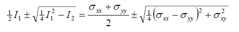
Let us consider a beam initially unstressed as shown in fig 1(a). Now the beam is subjected to a constant bending moment (i.e. ‘Zero Shearing Force') along its length as would be obtained by applying equal couples at each end. The beam will bend to the radius R as shown in Fig 1(b)
As a result of this bending, the top fibers of the beam will be subjected to tension and the bottom to compression it is reasonable to suppose, therefore, that somewhere between the two there are points at which the stress is zero.
The locus of all such points is known as the neutral axis. The radius of curvature R is then measured to this axis. For symmetrical sections the N. A. is the axis of symmetry but whatever the section N. A. will always pass through the center of the area or centroid.
The above restrictions have been taken so as to eliminate the possibility of 'twisting' of the beam.
Concept of pure bending:
Loading restrictions:
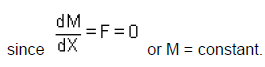
As we are aware of the fact internal reactions developed on any cross-section of a beam may consist of a resultant normal force, a resultant shear force, and a resultant couple. In order to ensure that the bending effects alone are investigated, we shall put a constraint on the loading such that the resultant normal and the resultant shear forces are zero on any cross-section perpendicular to the longitudinal axis of the member,
That means F = 0
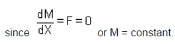
Thus, the zero shear force means that the bending moment is constant or the bending is the same at every cross-section of the beam. Such a situation may be visualized or envisaged when the beam or some portion of the beam, as been loaded only by pure couples at its ends. It must be recalled that the couples are assumed to be loaded in the plane of symmetry.
When a member is loaded in such a fashion it is said to be in pure bending. The examples of pure bending have been indicated in EX 1and EX 2 as shown below :

When a beam is subjected to pure bending are loaded by the couples at the ends, a certain cross-section gets deformed and we shall have to make out the conclusion that,
1. Plane sections originally perpendicular to the longitudinal axis of the beam remain plane and perpendicular to the longitudinal axis even after bending, i.e. the cross-section A'E', B'F' ( refer Fig 1(a) ) do not get warped or curved.
2. In the deformed section, the planes of this cross-section have a common intersection i.e. any time originally parallel to the longitudinal axis of the beam becomes an arc of a circle.
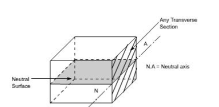
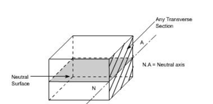
We know that when a beam is under bending the fibers at the top will be lengthened while at the bottom will be shortened provided the bending moment M acts at the ends. In between these, there are some fibers that remain unchanged in length that is they are not strained, that is they do not carry any stress. The plane containing such fibers is called a neutral surface.
The line of intersection between the neutral surface and the transverse exploratory section is called the neutral axis (N A).
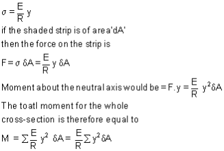
Bending Stresses in Beams or Derivation of Elastic Flexural formula :
In order to compute the value of bending stresses developed in a loaded beam, let us consider the two cross-sections of a beam HE and GF, originally parallel as shown in fig 1(a).when the beam is to bend it is assumed that these sections remain parallel i.e. H'E' and G'F', the final position of the sections, are still straight lines, they then subtend some angle θ.
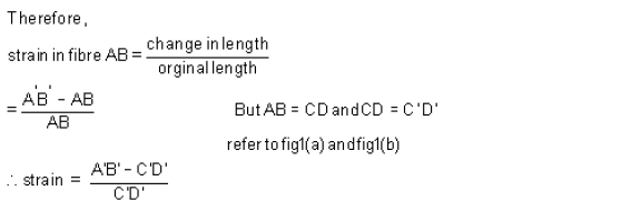
Consider now fiber AB in the material, at a distance y from the N.A, when the beam bends this will stretch to A'B'
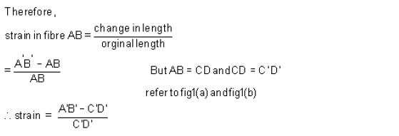
Since CD and C'D' are on the neutral axis and it is assumed that the Stress on the neutral axis zero. Therefore, there won't be any strain on the neutral axis.

Consider any arbitrary cross-section of beam, as shown above now the strain on fiber at a distance ‘y' from the N.A, is given by the expression.
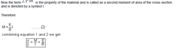
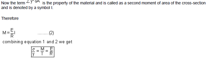
This equation is known as the Bending Theory Equation. The above proof has involved the assumption of pure bending without any shear force being present. Therefore this is termed as the pure bending equation. This equation gives the distribution of stresses which are normal to cross-section i.e. in the x-direction.
Section Modulus:
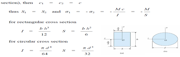
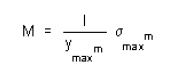
From a simple bending theory equation, the maximum stress obtained in any cross-section is given as
For any given allowable stress the maximum moment which can be accepted by a particular shape of the cross-section is therefore

For ready comparison of the strength of various beam cross-sections, this relationship is sometimes written in the form.
 Is termed as section modulus.
The higher value of Z for a particular cross-section, the higher the bending moment which it can withstand for given maximum stress.
Beam: loads acting transversely to the longitudinal axis the loads create shear forces and bending moments, stresses and strains due to V and M are discussed in this chapter lateral loads acting on a beam cause the beam to bend, thereby deforming the axis of the beam into curve line, this is known as the deflection curve of the beam.
The beams are assumed to be symmetric about the x-y plane, i.e. y-axis is an axis of symmetric of the cross-section, all loads are assumed to act in the x-y plane, then the bending deflection occurs in the same plane, it is known as the plane of bending the deflection of the beam is the displacement of that point from its original position, measured in the y-direction
Pure Bending and Non-uniform Bending
Pure bending:
M = constant V = dM / dx = 0
pure bending in simple beam and cantilever beam are shown
Non-uniform bending:
M ≠ constant
V = dM / dx ≠ 0
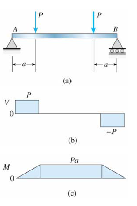
Simple beam with the central region in pure bending and end regions in non-uniform bending is shown
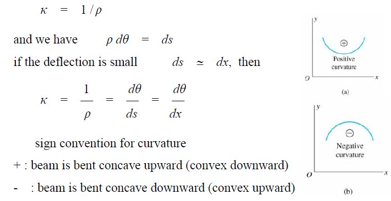
The curvature of a Beam
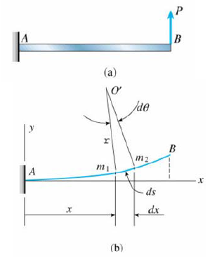
Consider a cantilever beam subjected to a load P

Choose 2 points m1 and m2 on the deflection curve, their normal intersect at point O', is called the centre of curvature, the distance m1O' is called the radius of curvature ρ, and the curvature K is defined as
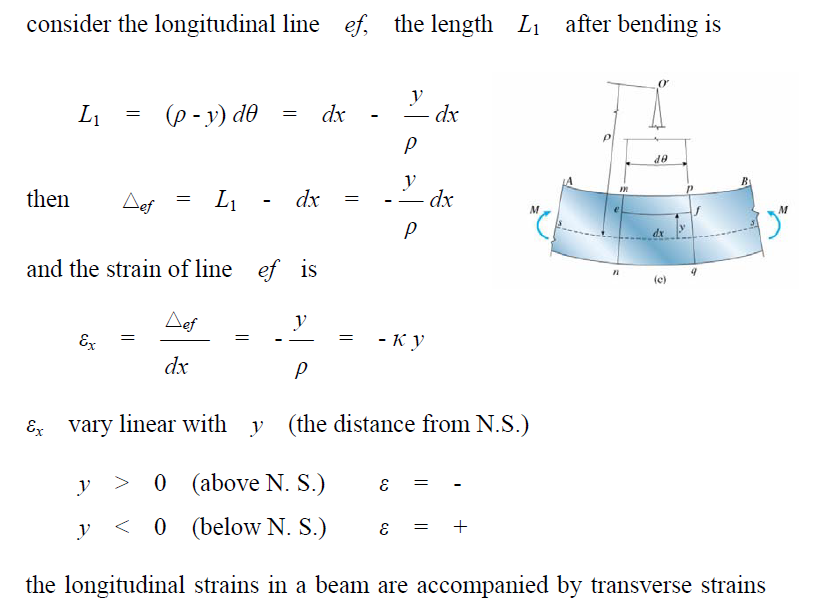
Longitudinal Strains in Beams
Consider a portion ab of a beam in pure bending produced by a positive bending moment M, the cross-section may be of any shape provided it is symmetric about y-axis under the moment M, its axis is bent into a circular curve, cross-section mn and pq remain plane and normal to longitudinal lines (plane remains plane can be established by experimental result)
The symmetry of the beam and loading, requires that all elements of the beam deform in an identical manner (∴ the curve is circular), this are valid for any material (elastic or inelastic) due to bending deformation, cross-sections mn and pq rotate w.r.t. each other about axes perpendicular to the xy plane longitudinal lines on the convex (lower) side (nq) are elongated, and on the concave (upper) side (mp) are shortened the surface ss in which longitudinal lines do not change in length is called the neutral surface, its intersection with the cross-sectional plane is called the neutral axis, for instance, the z-axis is the neutral axis of the cross-section
In the deformed element ρ the distance from O' to N.S. (or N.A.), thus ρdθ = dx

in the y and z directions because of the effects of Poisson's ratio.
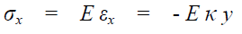
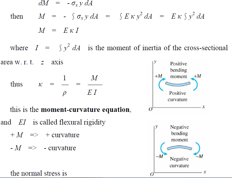
Normal Stress in Beams (Linear Elastic Materials)
∵e x occurs due to bending, ∴ the longitudinal line of the beam is subjected only to tension or compression if the material is linear elastic
then 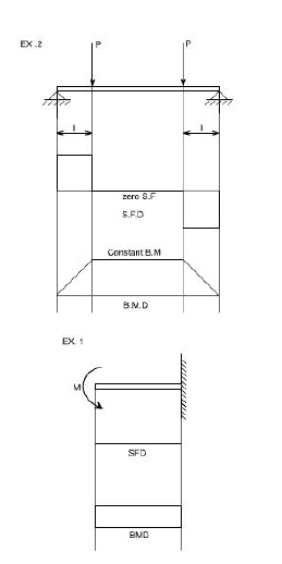
σ vary linear with distance y from the neutral surface consider a positive bending moment M applied, stresses are positive below N.S. and negative above N.S.
∵ No axial force acts on the cross-section, the only resultant is M, thus two equations must satisfy for static equilibrium condition.
E and K are constants at the cross-section, thus we have ∫y dA = 0
We conclude that the neutral axis passes through the centroid of the cross-section, also for the symmetrical condition in the y-axis, the y axis must pass through the centroid, hence, the origin of coordinates O is located at the centroid of the cross-section the moment resultant of stress  is
is

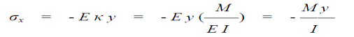
This is called the flexure formula; the stress σx is called bending stresses or flexural stresses.
The preceding analysis of normal stress in beams concerned pure bending, No shear force in the case of non-uniform bending (V≠0), shear force produces warping (out of plane distortion), plane section no longer remains plane after bending, but the normal stress σx calculated from the flexure formula are not significantly altered by the presence of shear force and warping we may justifiably use the theory of pure bending for calculating σx even when we have non-uniform bending the flexure formula gives results in the beam where the stress distribution is not disrupted by irregularities in the shape, or by discontinuous in loading (otherwise, stress concentration occurs).
Torsion
Definition of Torsion: Consider a shaft rigidly clamped at one end and twisted at the other end by a torque T = F.d applied in a plane perpendicular to the axis of the bar such a shaft is said to be in torsion.
Effects of Torsion: The effects of a torsional load applied to a bar are
(i) To impart an angular displacement of one end cross-section with respect to the other end.
(ii) To setup shear stresses on any cross-section of the bar perpendicular to its axis.
GENERATION OF SHEAR STRESSES
The physical understanding of the phenomena of setting up of shear stresses in a shaft subjected to a torsion may be understood from the figure.
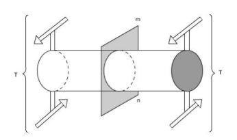
Fig: Here the cylindrical member or a shaft is in static equilibrium where T is the resultant external torque acting on the member. Let the member be imagined to be cut by some imaginary plane mn'.
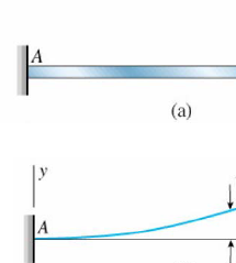
Fig 2: When the plane mn' cuts remove the portion on R.H.S. and we get a fig 2. Now since the entire member is in equilibrium, therefore, each portion must be in equilibrium. Thus, the member is in equilibrium under the action of resultant external torque T and developed resisting Torque Tr
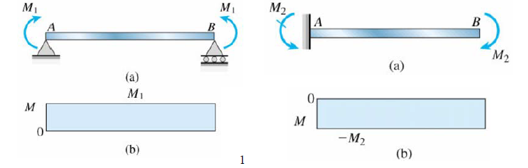
Fig 3: The Figure shows how the resisting torque Tr is developed. The resisting torque Tr is produced by virtue of infinite mal shear forces acting on the plane perpendicular to the axis of the shaft. Obviously, such shear forces would be developed by virtue of shear stresses.
Therefore we can say that when a particular member (say shaft in this case) is subjected to a torque, the result would be that on any element there will be shear stresses acting. While on other faces the complementary sheer forces come into the picture. Thus, we can say that when a member is subjected to torque, an element of this member will be subjected to a state of pure shear.
Shaft: The shafts are the machine elements that are used to transmit power in machines.
Twisting Moment: The twisting moment for any section along the bar/shaft is defined to be the
The algebraic sum of the moments of the applied couples that lie to one side of the section under consideration. The choice of the side, in any case, is of course arbitrary.
Shearing Strain: If a generator a b is marked on the surface of the unloaded bar, then after the twisting moment 'T' has been applied this line moves to ab'. The angle measured in radians, between the final and original positions of the generators, is defined as the shearing strain at the surface of the bar or shaft. The same definition will hold at any interior point of the bar.
Modulus of Elasticity in shear: The ratio of the shear stress to the shear strain is called the modulus of elasticity in shear OR Modulus of Rigidity and in represented by the symbol
The angle of Twist: If a shaft of length L is subjected to a constant twisting moment T along its length, then the angle through which one end of the bar will twist relative to the other is known as the angle of twist.
Despite the differences in the forms of loading, we see that there is a number of similarities between bending and torsion, including, for example, a linear variation of stresses and strain with the position.
In torsion, the members are subjected to moments (couples) in planes normal to their axes.
For the purpose of designing a circular shaft to withstand a given torque, we must develop an equation giving the relation between twisting moment, maximum shear stress produced, and a quantity representing the size and shape of the cross-sectional area of the shaft.
Not all torsion problems involve rotating machinery, however, for example, some types of
vehicle suspension systems employ torsional springs. Indeed, even coil springs are really curved members in torsion as shown in the figure.
Many torques carrying engineering members are cylindrical in shape. Examples are drive shafts, bolts, and screwdrivers.
Torsion of circular shafts Definition of Torsion: Consider a shaft rigidly clamped at one end and twisted at the other end by a torque T = F.d applied in a plane perpendicular to the axis of the bar such a shaft is said to be in torsion.
Effects of Torsion: The effects of a torsional load applied to a bar are
(i) To impart an angular displacement of one end cross-section with respect to the other end.
(ii) To setup shear stresses on any cross-section of the bar perpendicular to its axis.
Assumption:
(i) The material is homogenous i.e of uniform elastic properties exist throughout the material.
(ii) The material is elastic, follows Hook's law, with shear stress proportional to shear strain.
(iii) The stress does not exceed the elastic limit.
(iv) The circular section remains circular
(v) Cross-section remains plane.
(vi) Cross-section rotates as if rigid i.e. every diameter rotates through the same angle.
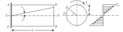
Consider now the solid circular shaft of radius R subjected to a torque T at one end, the other end being fixed Under the action of this torque a radial line at the free end of the shaft twists through an angle θ, point A moves to B, and AB subtends an angle ‘ γ' at the fixed end. This is then the angle of distortion of the shaft i.e the shear strain.
Since angle in radius = arc / Radius
arc AB = Rθ
= L γ [since L and γ also constitute the arc AB]
Thus, γ= Rθ / L (1)
From the definition of Modulus of rigidity or Modulus of elasticity in shear
A shaft will be said to be in torsion if it will be subjected with two equal and opposite torques applied at its two ends. When a shaft will be subjected to torsion or twisting moment, there will be developed shear stress and shear strain in the shaft material.
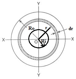
We will discuss here one case of a hollow circular shaft which will be subjected to torsion and we will secure here the expression for maximum torque transmitted by a hollow circular shaft.
We have the following information from the above figureRo = Outer radius of the hollow circular shaft
Ri = Inner radius of the hollow circular shaft
Do = Outer diameter of the hollow circular shaft
Di = Inner diameter of the hollow circular shaft
dr = Thickness of small elementary circular ring
r = Radius of the small elementary of a circular ring
q = Shear stress at a radius r from the centre of the hollow circular shaft
τ = Maximum shear stress at the outer surface of the shaft
dA = Area of the small elementary of a circular ring
dA = 2П x r x dr
Shear stress, at a radius r from the centre, could be determined as mentioned here
q/ r = τ / Ro
q = τ x r/ Ro
Turning force due to shear stress at a radius r from the centre could be determined as mentioned here
dF = q x dA
dF = τ x r/ Ro x 2П x r x dr
dF = τ/ Ro x 2П r2dr
The twisting moment at the circular elementary ring could be determined as mentioned here
dT = Turning force x r
dT = τ/ Ro x 2П r3dr
Total torque could be easily determined by integrating the above equation between limits Ri and Ro.

Therefore total torque transmitted by a hollow circular shaft will be given by the following formula
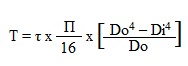
Torsion equation or torsion constant is defined as the geometrical property of a bar’s cross-section that is involved in the axis of the bar that has a relationship between the angle of twist and applied torque whose SI unit is m4. The torsion equation is given as follows:
T/J= τ/r=GΘ/L
Following are the assumptions made for the derivation of the torsion equation:
Consider a solid circular shaft with radius R that is subjected to a torque T at one end and the other end under the same torque.
T = Maximum twisting torque or twisting moment
D = Diameter of shaft
R = Radius of shaft
J = Polar Moment of Inertia
τ= Maximum Permissible Shear stress (Fixed for a given material)
G = Modulus of rigidity
θ= Angle of twist (Radians) = angle D'OD L = Length of the shaft.
?= Angle D'CD = Angle of Shear strain
Than Torsion equation is: T/J = τ/R = G. θ /L
Let the shaft is subjected to a torque or twisting moment 'T'. And hence every C.S. of this shaft will be subjected to shear stress.
Now distortion at the outer surface = DD'
Shear strain at outer surface = Distortion/Unit length tan? = DD'/CD
i.e. shear stress at the outer surface (tan? ) = DD'/L or = DD'/L ...(i)
Now DD' = R.θ or ?= R .θ /L ...(ii)
Now G = Shear stress induced/shear strain produced
G = τ / (R. θ /L);
or; τ/R = G. θ /L …..(A);
This equation is called Stiffness equation.
Hear G, θ , L are constant for a given torque 'T'. That is proportional to R
If τ r be the intensity of shear stress at any layer at a distance 'r' from the canter of the shaft, then;
Now from equation (ii) T = (τ/R) J
or τ/R = T/J; ..(B)
This equation is called a strength equation
The combined equation A and B; we get
T/J = τ/R = G. θ /L
This equation is called a Torsion equation.
From the relation T/J = τ/R We have T = τ .J/R = τ .ZP
For the given shaft IP and R are constants and IP/R is thus constant and is called POLAR MODULUS(ZP). of the shaft section.
The polar modulus of the section is thus a measure of the strength of the shaft in the torsion.
TORSIONAL RIGIDITY or Torsional Stiffness (K): = G.J/L = T/θ
Consider a bar or shaft of circular cross-section twisted by a couple of T, assume the left-hand end is fixed and the right-hand end will rotate a small angle ϕ, called angle of a twist if every cross-section has the same radius and subjected to the same torque, the angle ϕ (x) will vary linearly between ends under twisting deformation, it is assumed
1. Plane section remains plane
2. Radii remaining straight and the cross-sections remaining plane and circular
3. if ϕ is small, neither the length L nor its radius will change consider an element of the bar dx, on its outer surface we choose a small element abcd,

During twisting the element rotate a small angle d, the element is in
a state of pure shear, and deformed into ab'c'd, its shear strain γmax is
γmax = bb’/ab = r d ϕ / dx
d ϕ / dx represents the rate of change of the angle of twist ϕ, denote θ= d ϕ / dx as the angle of twist per unit length or the rate of twist, then γmax = r θ in general, ϕ and θ are a function of x, in the special case of pure torsion, θ is constant along the length (every cross-section is subjected to the same torque) θ = ϕ/L and γmax = rθ/L and the shear strain inside the bar can be obtained

γ = ρ.θ=ρ. γmax / r
γmin = r1 /r2 γmax
For a circular tube, it can be obtained .the above relationships are based only upon geometric concepts, they are valid for a circular bar of any material, elastic or inelastic, linear or nonlinear.
References:
1. Beer, F.P and Johnston Jr. E.R., “Vector Mechanics for Engineers (In SI Units): Statics and Dynamics”, 8th Edition, Tata McGraw-Hill Publishing company, New Delhi (2004).
2. Vela Murali, “Engineering Mechanics”, Oxford University Press (2010).
3. A Textbook of Engineering Mechanics, R.K. Bansal, Laxmi Publications.
4. Engineering Mechanics, R.S. Khurmi, S.Chand Publishing.
5. Meriam J.L. and Kraige L.G., “Engineering Mechanics- Statics - Volume 1, Dynamics- Volume 2”, Third Edition, John Wiley & Sons (1993).
6. Rajasekaran S and Sankarasubramanian G., “Engineering Mechanics Statics and Dynamics”, 3 rd Edition, Vikas Publishing House Pvt. Ltd., (2005).
7. Bhavikatti, S.S, and Rajashekarappa, K.G., “Engineering Mechanics”, New Age International (P) Limited Publishers, (1998).
8. Engineering mechanics by Irving H. Shames, Prentice-Hall.


