Conventional Manufacturing Processes
1.1.1 Metal casting processes and equipment
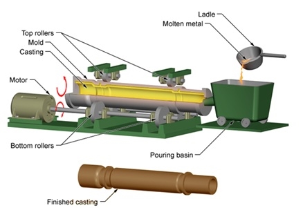
Fig 1 metal casting and finishing
Casting Steps
We should concentrate on the following for successful casting operation:
Casting Terminology
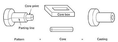
Fig 2 Casting terminology
1.1.2 Heat transfer and solidification
Heat transfer and solidification kinetics in the meniscus region during casting have been examined using a two-dimensional transient heat-flow analysis. The effects of the various parameters involved were assessed by determining the variation in position with a time of a rigid, partially solidified interface. For normal conditions when casting in a chill mould, solid was found to grow over the meniscus at a very early stage. Heat extraction by the mould was then the controlling factor. It was predicted that changes in superheat and alloy composition would produce significant changes in the amount of solid formed over the meniscus, while heat lost to the melting cover and meniscus height became important only if the changes were extreme. The results of the predictions are in agreement with experimental observations reported previously. It is concluded from these findings that the meniscus-solidification mechanism can successfully account for the occurrence of surface rippling during static and continuous casting.
1.1.3 Shrinkage
Metal shrinks as it transforms from liquid to solid (known as solidification shrinkage) and undergoes additional thermal contraction as it cools to room temperature. Cast parts are therefore designed with shrinkage allowances to result in parts of the desired dimensions. Cast steel, for example, will shrink about ¼ in. per foot and produce rough-looking castings. Shrinkage allowances are known for various metals and an experienced mould designer will take the shrinkage into account when designing a mould. For more information on casting in general please refer to our article on Types of Casting Processes.
Shrinkage can also cause defects in cast products which can lead to failure, leakage, and so on. Sometimes these defects appear on the surface of the casting and can be detected visually or through dye penetrant or similar non-destructive procedures. Sometimes the defects are internal to the casting and require X-ray inspection or destructive tests to uncover. These defects are collectively known as open- and closed-shrinkage defects.
Open Shrinkage Defects
If the metal cools and shrinks with insufficient liquid available to fill any voids, pipes may form on the surface and extend into the body of the casting. Similarly, defects that form on the surface and spread across the face are sometimes called cave defects, or sinks. In both instances, the defects are open to the atmosphere and air takes the place of molten metal.
Cracks and hot tears usually form in the final stages of solidification and can be localized around abrupt changes where stress concentration exists such as a thin web connecting two heavy sections. They can also occur where insufficient draft in the part exists and in heavy sections where heat pools.
Closed Shrinkage Defects
Porosity is one of the main defects in castings and is caused by both trapped gases in the molten metal and as the casting shrinks during cooling. Shrinkage porosity is by far the most common type and can usually be detected on the surface of a cast part by what appear to be small holes or cracks. These holes may seem round but are angular in shape and tend to form branching internal fractures. Thick multi-angled parts are most susceptible to such shrinkage, which occurs as the metal cools and solidifies in a non-uniform pattern. Porosity can exist in the interior of casting as well, without necessarily showing on the surface of a part. This occurs when liquid metal is surrounded by solidified metal and molten metal is unable to fill in behind the liquid as it cools and shrinks.
The most common causes of shrinkage are related to the casting sprue, which is the passage through which molten metal is poured into a mould. In some areas, such as the heavy sections of the mould, the metal takes longer to contract and solidify which reduces feed material availability and increases the likelihood of shrinkage, especially if the sprue is too small for the volume of flow. A properly sized sprue attached directly to the heavy section can fill the shrinkage cavity and provide the feed material necessary to counteract shrinkage as cooling occurs. Besides, using a rounded, rather than a flat or square, gate on the sprue can further reduce the risk of forming defects.
Using a narrow or tapered sprue can result in the molten metal being sprayed rather than poured into the cavity. When this happens, certain sections of the workpiece begin to solidify before the entire mould is filled. Molten flow into the cavity should be as uniform as possible, and a larger central sprue or a multiple-sprue arrangement can help achieve an even supply of material.
Risers are used to ensure that sufficient molten material is available to fill in where the part is solidifying and shrinking. Risers should be sized such that they are the last parts to freeze. Sometimes insulation is added to ensure this.
Shrinkage defects can be reduced by employing local heat dissipation, such as chills (metal inserted in the mould that melts during the pour), in areas where heat tends to pool--in thick, heavy sections, for example.
Simulation software can be used to optimize the filling of cavities through improved runner and gate designs and can predict the occurrence of shrinkage porosity. The flow of material through the mould can be controlled by good mould design and employment of techniques such as directional solidification.
Other shrinkage defects include:
How Temperature Affects Casting Shrinkage
To reduce the potential for metal casting shrinkage, it is helpful to work within a delineated temperature range. Metal should be heated to achieve appropriate molten characteristics, generally to 100°F above its flow point. Any overheating should be avoided Maintaining mould temperatures of 800-1000°F below the melting point of the metal is a generally accepted rule. Another useful rule to know is the casting cooling rate, which can be around 100°F per minute after pouring is complete. Attention paid to the fluidity of the molten pour can also influence how shrinkage is addressed.
1.1.4 Riser design
1. When a molten metal is paused into the cavity its temperature then is much higher than its melting point.
2. Say, if its melting point is 500°C then its pausing temperature would be around 700°C.
3. This difference between pausing and melting point is known as “Degree of superheat”.
4. This ensures the fidelity in the metal.
5. The molten metals while cooling undergo various changes. Its volume reduces due to densification as it is a solidifier.
6. The molten metal firstly cooler down to its freezing temperature in the liquid phase only by losing sensible heat to the atmosphere around it.
7. Then a phase changes occur as it further looser latent heat. In both the above-mentioned step contraction happens that is known as “Liquid Contraction”.
8. Further the metal now in solid-state cools down to room temperature. During this proves the contraction happens which is known as “Solid Contraction”.
9. “Liquid Contractions” are compensated by using “Risers” whereas “Solid Contractions” are handled using “allowances”.
10. Riser supplies hot molten metal when the casting solidifier. That means it has to contain metal in the liquid phase even when the casting has started to solidify, in the same mould.
11. This could be achieved by designing the riser, such that it has the least surface area to exchange heat with the atmosphere.
12. One such shape is a sphere. Sphere has the least surface area for a given volume.
13. The problem with spherical risers is that when the molten metal solidifier starts from the surface and thus blocks the outlet for molten metal.
14. The next best is a cylinder. Now there are 2 ways in which are can place a cylindrical riser. 1. Top cylindrical riser 2. Side Cylindrical riser
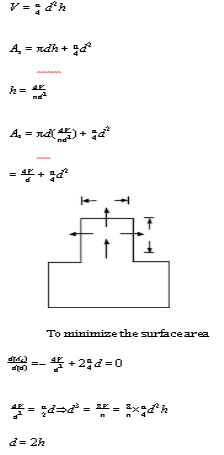
Thus, to minimize the surface area diameter should be twice the height.
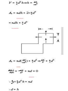
So, in order to minimize the surface area diameter should be equal to its height. There are 4 conditions that are considered before designing a riser.
Condition-1 (Necessary condition) The volume of the riser should be thrice the shrinkage volume. Shrinkage volume is the volume reduction occurring during the liquid contraction.
Condition-2 Location of the riser should be in such a manner that it should be able to supply molten easily to the part where it is needed the most.
Condition-3 Shape of the riser should be selected for the least surface area for a given volume.
Method of Riser Design
Condition-1 (Necessary condition) The volume of the riser should be thrice the shrinkage volume. Shrinkage volume is the volume reduction occurring during the liquid contraction.
Fig 3
1.1.5 Casting defects and residual stresses
Casting Defects
Some defects are common to any and all casting processes. These defects are as follows:
Misruns: These are castings that solidify before completely filling the mould cavity.
Causes of misrun include (i) fluidity of the molten metal is insufficient, (ii) pouring temperature is too low, (iii) pouring is done too slowly, and/or (iv) cross-section of the mould cavity is too thin.
Cold Shuts: These occur when two portions of the metal flow together but there is a lack of fusion between them due to premature freezing. Its causes are similar to those of a misrun.
Cold shots: These result from splattering during pouring, causing the formation of solid globules of metal that become entrapped in the casting. Pouring procedures and gating system designs that avoid splattering can prevent this defect.
Shrinkage cavity: It is a depression in the surface or an internal void in the casting, caused by solidification shrinkage that restricts the amount of molten metal available in the last region to freeze. It often occurs near the top of the casting; in which case it is called a ‘‘pipe.’’ This problem can often be solved by proper riser design.
Micro-porosity: It consists of a network of small voids distributed throughout the casting caused by localized solidification shrinkage of the final molten metal in the dendritic structure. The defect is usually associated with alloys, because of the protracted manner in which freezing occurs in these metals.
Hot tearing or hot cracking: It occurs when the casting is restrained from a contraction by an unyielding mould during the final stages of solidification or early stages of cooling after solidification. This defect is because of the separation of the metal at a point of high tensile stress caused by the metal’s inability to shrink naturally. In sand casting and other expendable-mould processes, it is prevented by compounding the mould to be collapsible. In permanent-mould processes, hot tearing is reduced by removing the part from the mould immediately after solidification.
 Fig 4 Common defects in casting
Some defects are related to the use of sand moulds, and therefore they occur only in sand castings. Other expendable-mould processes are also susceptible to these problems but to a lesser degree.
Defects found primarily in sand castings are as follows:
Sand blow: It is a defect consisting of a balloon-shaped gas cavity caused by the release of mould gases during pouring. It occurs at or below the casting surface near the top of the casting. Low permeability, poor venting, and high moisture content of the sand mould are the usual causes of Sand blow.
Pinholes: These are also caused by the release of gases during pouring, consist of many small gas cavities formed at or slightly below the surface of the casting.
Sand wash: It is an irregularity in the surface of the casting that results from erosion of the sand mould during pouring, and the contour of the erosion is formed in the surface of the final cast part.
Scabs: These are rough areas on the surface of the casting due to encrustations of sand and metal. It is caused by portions of the mould surface flaking off during solidification and becoming embedded in the casting surface.
Penetration: It is a surface defect that occurs when the fluidity of the liquid metal is high, and it penetrates the sand mould or sand core. Upon freezing, the casting surface consists of a mixture of sand grains and metal. Harder packing of the sand mould helps to alleviate this condition.
Mould shift: It is a defect caused by a sidewise displacement of the mould cope relative to the drag, resulting in a step in the cast product at the parting line.
Core shift: It is similar to mould shift, but it is the core that is displaced, and the displacement is usually vertical. Core shift and mould shift are caused by the buoyancy of the molten metal.
Mould crack: It occurs when mould strength is insufficient, and a crack develops, into which liquid metal can seep to form a ‘‘fin’’ on the final casting.
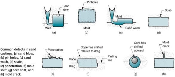
Fig 5 Common defect in sand casting
Residual Stresses
Residual stresses are those stresses that remain in an object (in particular, in a welded component) even in the absence of external loading or thermal gradients. In some cases, residual stresses result in significant plastic deformation, leading to warping and distortion of an object. In others, they affect susceptibility to fracture and fatigue.
What Causes Residual Stress
Residual stresses are generated when an object (especially a welded component) is stressed beyond its elastic limit, resulting in plastic deformation. There are three primary reasons for these stresses arising:
Thermal Variations
Phase Transformations
When a material undergoes a phase transformation, a volume difference between the newly formed phase and the surrounding material, which has yet to undergo phase transformation, occurs. The volume difference causes expansion or contraction of the material, resulting in residual stress.
Mechanical Processing
Residual stress also occurs when plastic deformation is non-uniform through the cross-section of an object undergoing a manufacturing process, such as bending, drawing, extruding, and rolling. When a material undergoes deformation, one part is elastic, and another plastic. Once the load is removed, the material tries to recover the elastic part of the deformation but is inhibited from full recovery due to the adjacent plastically deformed material.
What Effects Do They Have
Depending on the application, residual stresses can be positive or negative. For example, residual stresses are implemented in the designs of certain applications for positive effects. This can be achieved through laser peening, which imparts compressive residual stresses to the surface of an object, allowing for the strengthening of thin sections or the toughening of brittle surfaces.
Typically, however, residual stresses have negative effects. Residual stresses are often invisible to a manufacturer, unless they result in significant distortion, but can negatively affect structural integrity. For example, thick-walled structures in the as-welded condition are more prone to brittle fracture than a structure that has been stress-relieved.
The undesired stresses also have an effect on fatigue performance.
It has long been recognized that, for non-welded materials under fatigue loading conditions, only the tensile parts of the applied stress cycle contribute to fatigue crack growth (see the lower part of Figure 1.) Conversely, for joints in the as-welded condition, the effects of welding residual stress need to be added to those of applied cyclic stress, with the result that the whole fatigue cycle (tensile and compressive) gives rise to fatigue damage (see the upper part of Figure 1).
 Figure 6 Effect of welding residual stress on fatigue damage.
Fortunately, the effects of welding residual stresses on both fracture and fatigue have been written into codes and standards in such a way that most users are unaware of them, and do not need to consider them explicitly. Nevertheless, there are particular cases where quantification of residual stresses is necessary.
How Can I Measure Residual Stress
Key points
Sheet-bulk metal forming is defined as the forming of sheets with an intended three-dimensional material flow as in bulk forming processes. This new process class includes several conventional forming operations that are combined and extended in their application, and are oftentimes conducted in conjunction with conventional sheet forming processes. One central characteristic is given by the complex interaction between forming zones of high and low strains that possess three-dimensional, as well as two-dimensional stress and strain states. All forming operations are applied on semi-finished parts of 1 to 5 mm thickness with the intention to form local shape elements projecting out of the plane which is in the dimension of the sheet thickness. Besides manufacturing of functional integration, SBMF can also be used to redirect material on sheets in order to produce semi-finished parts with tailored properties. In forming processes are categorized with respect to the stress states during the forming operation.
However, this classification is not applicable to sheet-bulk metal forming processes since characteristics of multiple processes can merge in some cases. Furthermore, the geometry of the semi-finished parts in question is not respected. In order to solve this challenge, a classification that enables a distinction of possible processes by the tool motion in use is proposed in. As Fig. 5 shows, upsetting, ironing, forging, and coining can be assigned to the group of linear motions whereas rotational movement can be found in flow forming, orbital forming, and boss forming. Furthermore, all processes can be descripted by the resulting change in sheet thickness, the possibility of combinations with sheet forming operations, and by the demand for forming force. Process forces are particularly dependent on the effective contact area between workpiece and tool during the forming operation. High contact areas result in high process forces, whereas small contact areas demand less force. Due to this circumstance upsetting, forging and coining possess the highest force demands due to their typically large contact areas. One strategy to overcome this challenge is the use of incremental forming processes like orbital forming or flow forming.
Such processes are characterized by small but moving contact and forming zone.
As listed in Fig. 5, it is possible to both locally reduce or heighten sheet thickness in most sheet-bulk metal forming processes. Additionally, a combination with conventional sheet forming operations is predominantly possible. The circumstance that both aspects apply to forging and upsetting makes those
operations particularly promising methods if complex sheet products of high functional integration.
Sheet-bulk metal forming is defined as the forming of sheets with an intended three-dimensional material flow as in bulk forming processes. This new process class includes several conventional forming operations that are combined and extended in their application, and are oftentimes conducted in conjunction with conventional sheet forming processes. One central characteristic is given by the complex interaction between forming zones of high and low strains that possess three-dimensional, as well as two-dimensional stress and strain states. All forming operations are applied on semi-finished parts of 1 to 5 mm thickness to form local shape elements projecting out of the plane which is in the dimension of the sheet thickness. Besides manufacturing of functional integration, SBMF can also be used to redirect material on sheets in order to produce semi-finished parts with tailored properties. In forming processes are categorized with respect to the stress states during the forming operation. However, this classification is not applicable to sheet-bulk metal forming processes since characteristics of multiple processes can merge in some cases. Furthermore, the geometry of the semi-finished parts in question is not respected. To solve this challenge, a classification that enables a distinction of possible processes by the tool motion in use is proposed in. As Fig. 5 shows, upsetting, ironing, forging, and coining can be assigned to the group of linear motions whereas rotational movement can be found in flow forming, orbital forming, and boss forming. Furthermore, all processes can be descripted by the resulting change in sheet thickness, the possibility of combinations with sheet forming operations, and by the demand for forming force. Process forces are particularly dependent on the effective contact area between workpiece and tool during the forming operation. High contact areas result in high process forces, whereas small contact areas demand less force. Due to this circumstance upsetting, forging and coining possess the highest force demands due to their typically large contact areas. One strategy to overcome this challenge is the use of incremental forming processes like orbital forming or flow forming.
Such processes are characterized by small but moving contact and forming zone.
As listed in Fig. 5, it is possible to both locally reduce or heighten sheet thickness in most sheet-bulk metal forming processes. Additionally, a combination with conventional sheet forming operations is predominantly possible. The circumstance that both aspects apply to forging and upsetting makes those operations particularly promising methods if complex sheet products of high functional integration Sheet-bulk metal forming is defined as forming of sheets with an intended three-dimensional material flow as in bulk forming processes. This new process class includes several conventional forming operations that are combined and extended in their application, and are oftentimes conducted in conjunction with conventional sheet forming processes. One central characteristic is given by the complex interaction between forming zones of high and low strains that possess three-dimensional as well as two-dimensional stress and strain states.
All forming operations are applied on semi-finished parts of 1 to 5 mm thickness with the intention to form local shape elements projecting out of the plane which is in the dimension of the sheet thickness. Besides manufacturing functional integration SBMF can also be used to redirect material on sheets to produce semi-finished parts with tailored properties. The forming processes are categorized with respect to the stress states during the forming operation. However, this classification is not applicable to sheet-bulk metal forming processes since characteristics of multiple processes can merge in some cases.
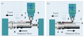
Fig 7 (a) Forward flow forming and (b) Backward flow farming
Furthermore, the geometry of the semi-finished parts in question is not respected. In order to solve this challenge, a classification that enables a distinction of possible processes by the tool motion in use is proposed in As Fig. 5 show, upsetting, ironing, forging, and coining can be assigned to the group of linear motions whereas rotational movement can be found in flow forming, orbital forming and boss forming. Furthermore, all processes can be descripted by the resulting change in sheet thickness, the possibility of combinations with sheet forming operations, and by the demand on forming force.
Process forces are particularly dependent on the effective contact area between workpiece and tool during the forming operation. High contact areas result in high process forces, whereas small contact areas demand less force. Due to this circumstance upsetting, forging and coining possess the highest force demands due to their typically large contact areas. One strategy to overcome this challenge is the use of incremental forming processes like orbital forming or flow forming. Such processes are characterized by small but moving contact and forming zone. As listed in Fig., it is possible to both locally reduce or heighten sheet thickness in most sheet-bulk metal forming processes.
Additionally, a combination with conventional sheet forming operations is predominantly possible. The circumstance that both aspects apply to forging and upsetting makes those operations particularly promising methods if complex sheet products of high functional integration
1.3.1 Plastic deformation
When a sufficient load is applied to a metal or other structural material, it will cause the material to change shape. This change in shape is called deformation. A temporary shape change that is self-reversing after the force is removed, so that the object returns to its original shape, is called elastic deformation. In other words, elastic deformation is a change in the shape of a material at low stress that is recoverable after the stress is removed. This type of deformation involves stretching of the bonds, but the atoms do not slip past each other.
When the stress is sufficient to permanently deform the metal, it is called plastic deformation. As discussed in the section on crystal defects, plastic deformation involves the breaking of a limited number of atomic bonds by the movement of dislocations. Recall that the force needed to break the bonds of all the atoms in a crystal plane all at once is very great. However, the movement of dislocations allows atoms in crystal planes to slip past one another at much lower stress levels. Since the energy required to move is lowest along the densest planes of atoms, dislocations have a preferred direction of travel within a grain of the material. This results in a slip that occurs along parallel planes within the grain. These parallel slip planes group together to form slip bands, which can be seen with an optical microscope. A slipped band appears as a single line under the microscope, but it is made up of closely spaced parallel slip planes as shown in the image.
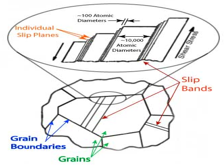
Fig 8
For most metallic materials, the elastic deformation region is relatively small. At some point, the strain is no longer proportional to the applied stress. At this point, bonds with original atom neighbours start to break and reform with a new group of atoms. When this occurs and the stress is relieved, the material will no longer return to its original form, i.e., the deformation is permanent and non-recoverable. The material has now moved into the region referred to as plastic deformation. In practice, it is difficult to identify the exact point at which material moves from the elastic region to the plastic region. As shown in the figure below, a parallel line offset by 0.002 strain is drawn. Where that line intercepts the stress-strain curve is identified as the yield strength. The yield strength is equal to the stress at which noticeable plastic deformation has occurred.
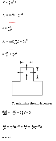
Fig 9 Stress and strain
For many materials, the stress-strain curve looks like the curve shown in the figure below. As the stress is increased from zero, the strain increases linearly until it starts to deviate from linear at the yield strength. For increasing stress, the curve proceeds to a maximum at which point it curves downward toward the fracture point. The maximum corresponds to the tensile strength, which is the maximum stress value for the curve, and is indicated by M in the figure. The fracture point is the point at which the material ultimately breaks, indicated by F in the figure.
1.3.2 Yield criteria
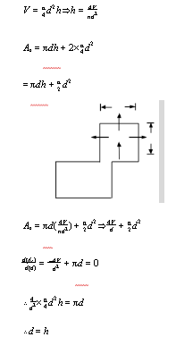
Fig 10
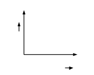
Fig 11 maximum shear stress criterion
Key points
1) When a sufficient load is applied to a metal or other structural material, it will cause the material to change shape.
2) The yield strength or yield point of a material is defined as the stress at which a material begins to deform plastically.
What is Hot Working
Re-crystallization temperature is the temperature at which atomic mobility can be repaired when any defect was present in the metal caused by the working process. In this process, the metal is heated to the plastic state, and then the pressure is applied to get various sizes and shapes. When the pressure is applied, the metal grain size will be varied, and the metal’s mechanical properties are improved.
If the pressure is applied by a hand hammer, then it is called hand or smith forging. If hand hammering is replaced by power hammers, then it is called hammer forging. Such a type of hot working of metals is called hot forging. Hot-working can be used for forging, extrusion, and drawing, etc.
When metals are worked above the re-crystallization temperature, then it becomes plastic and causes the growth of grains. During the hot working, the grains become loosened in their structure, and they realign properly. Only small pressure is required to shape the metal.
Advantages of Hot Working
1. It is applicable for mass production work.
2. The metal size and shape can be easily changed.
3. Metalworking is done under high temperatures; therefore, larger deformation is possible.
4. Metal grain structure will be refined.
5. Stresses and other defects can be minimized.
6. Hot-working leads to a homogeneous structure of metal without defects and blowholes.
7. Mechanical, physical, and chemical properties of metals can be improved.
8. Hot-working removes all types of imperfections caused by the Gas pores and composition differences.
9. Metal reaches to anisotropic behaviour.
10. Metal regains softness and ductility after the process.
11. Hot working is a fast, reliable, and economical process.
Disadvantages of Hot working
What is Cold Working
Soft, ductile, and malleable metals can be easily worked with cold working. But this process leads to hardness and distorted grain structure. The cold working process is used in the rolling, bending, spinning process, etc.
The cold working process also affects the following mechanical properties of metals significantly.
1. Hardness.
2. Yield Strength.
3. Ductility.
4. Tensile Strength.
Advantages of Cold Working
1. Dimensional accuracy can be maintained.
2. No heating of metals.
3. Better surface finish can be achieved since there is no oxidation during the cold working of metals.
4. Strength and hardness of the metal are increased.
5. Due to cold working, metal gains strength and hardness.
6. Better strength and wear properties of the material can be achieved.
Disadvantages of Cold Working
1. It leads to brittleness if the metals are worked under cold working.
2. Metals hardness is increased.
3. Cold worked components require a heat-treatment process.
4. Only ductile and malleable materials are suitable for cold working.
5. Greater force is essential for deformation. Therefore powerful machines are required.
Key points:
1) If the metalworking process is carried out above its re-crystallization temperature, it is called hot working.
2) If the metalworking process is carried out at a temperature below the re-crystallization temperature, it is called a cold working process
Metal forming: Large set of manufacturing processes in which the material is deformed plastically to take the shape of the die geometry. The tools used for such deformation are called a die, punch, etc. depending on the type of process.
Plastic deformation: Stresses beyond the yield strength of the workpiece material is required.
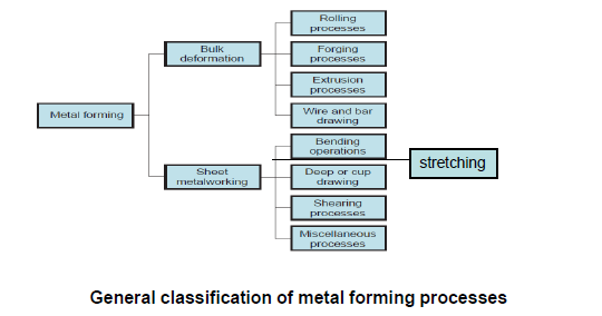
Fig 12
Classification of basic bulk forming processes

Fig 13
Bulk-forming: It is a severe deformation process resulting in massive shape change. The surface-area-to-volume of the work is relatively small. Mostly done in hot working conditions.
Rolling: In this process, the workpiece in the form of a slab or plate is compressed between two rotating rolls in the thickness direction, so that the thickness is reduced. The rotating roll draws the slab into the gap and compresses it. The final product is in the form of a sheet.
Forging: The workpiece is compressed between two dies containing shaped contours. The die shapes are imparted into the final part.
Extrusion: In this, the workpiece is compressed or pushed into the die opening to take the shape of the die hole as its cross-section. Wire or rod drawing: similar to extrusion, except that the workpiece is pulled through the die opening to take the cross-section.
Classification of basic sheet forming processes

Fig 14
Sheet forming: Sheet metal forming involves forming and cutting operations performed on metal sheets, strips, and coils. The surface-area-to-volume ratio of the starting metal is relatively high. Tools include punch, die that are used to deform the sheets.
Bending: In this, the sheet material is strained by a punch to give a bent shape (angle shape) usually in a straight axis.
Deep (or cup) drawing: In this operation, the forming of a flat metal sheet into a hollow or concave shape like a cup is performed by stretching the metal in some regions. A blank-holder is used to clamp the blank on the die, while the punch pushes into the sheet metal. The sheet is drawn into the die hole taking the shape of the cavity.
Shearing: This is nothing but the cutting of sheets by shearing action.
Powder technology is the science for the manufacture of parts from metal powders by compaction and heating that creates a homogeneous mass. Heating is executed in a furnace and is called sintering. The temperature at which sintering is performed is lower than the melting point of the powdered material. Sintering consists of diffusion in a solid-state by which particles of compacted powder are bonded together. This is the basic working principle of powder technology.
The powder metallurgy technique finds use in various industries and manufacturing processes. It has become very popular in a very short span of time because of its efficiency, durability, and reliable output. Some of them are mentioned here.
Applications of Powder Metallurgy in Industries
The powder metallurgy technique finds use in various industries and manufacturing processes. It has become very popular in a very short span of time because of its efficiency and reliable output. Some of them are mentioned here.
Parts with irregular curves or recesses that are hard to the machine can be manufactured using the powder metallurgy techniques. It is suitable for high-volume and mass production with practically negligible wastage of the manufacturing material. The process of secondary machining is virtually eliminated or reduced to a negligible extent by the technique of powder metallurgy and it helps in improving efficiency by a huge margin. Cams, sprockets, pawls, iron bearings, sintered bronze, ratchets and carbide tooltips are the most commonly manufactured items with the help of powder technology.
Tools produced using powder metallurgy techniques have high porosity and are very good at soaking oil. Compaction of constituent materials means strong internal structure resulting in strong bonding between the material constituents and thus producing durable machine equipment or tool. Longer life and strong structure are two major characteristics of tools or equipment produced using this technique.
Processes of Powder Technology
The processes involved in powder metallurgy are the following:
Pressing: The cavity of the die is filled with a specified quantity of blended powder, necessary pressure is applied, and then the compacted part is ejected. Pressing is performed at room temperature, while the pressure is dependent upon the material, properties of the powder used, and the density required of the compaction. Friction between the powder and the wall of the die opposes the application of a proper pressure that decreases with depth and thus causes uneven density in the compact. Thus the ratio of length and diameter is kept low to prevent substantial variations in density.
Sintering: Changes occur during sintering, including changes in size, configuration, and the nature of pores. Commonly used atmospheres for sintering are hydrogen, carbon monoxide, and ammonia. Sintering operation ensures that powder particles are bonded strongly and that better alloying is achieved.
Properties of Metal Powders
References:
1. Kalpakjian and Schmid, Manufacturing processes for engineering materials (5th Edition)-Pearson India, 2014.
2. Mikell P. Groover, Fundamentals of Modern Manufacturing: Materials, Processes, and Systems.
3. Manufacturing Technology by P.N. Rao., MCGRAW HILL INDIA.
4. Materials and Manufacturing by Paul Degarmo.
5. Manufacturing Processes by Kaushish, PHI.
6. Principles of Foundry Technology, Jain, MCGRAW HILL INDIA
7. Production Technology by RK Jain.
8. Degarmo, Black &Kohser, Materials and Processes in Manufacturing.