Metal Cutting
2.1.1 Single-point cutting
Single Point Cutting Tool is a tool that helps to perform several operations (like Turning, Facing, Producing Flat surface) on Lathe, Shaper, Planer Machine.
This tool consists of a sharpened cutting part called its point and the shank.
The point of the tool is bounded by the face (along which the chips slide as they are cut by the tool), the side flank or major flank the end flank or minor flank, and the base. As we know we perform several operations on the lathe (like turning, facing) from the single-point cutting tool. Design and fabrication are very easy for this tool. This tool can be made at a very cheaper rate as compared to others.
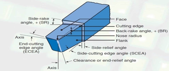
Fig 1 single point cutting tool
Single Point Cutting Tool Types:
There are only two types of the tool:
1. Single Point cutting tool:
2. Multi-Point cutting tool:
Single Point Cutting Tool Material:
This tool can be made from several materials like:
Single Point Cutting Tool Geometry / Nomenclature:
Angle:
Here you can see in this diagram:
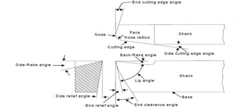
Fig 2
This is the main body of the tool. The shank is used to hold the tool (i. e tool holder).
The surface or surface below, and adjacent to the cutting edge is called the flank of the tool.
The surface on which the chips slide is called the face of the tool.
It is the intersection of the flan and the base of the tool. It is a curved portion at the bottom of the tool.
It is the point where the side cutting edge and end cutting edge intersects.
The nose radius will provide long life, and also a good surface finishes with it a sharp point on the nose.
It is the edge on the face of the tool which removes the material from the workpiece.
The tool cutting edge consists of side cutting edge (major cutting edge), end cutting edge (minor cutting edge, and the nose).
This angle also is known as the lead angle. This is the angle between the side cutting edge, and side of the tool shank.
This is the angle between the end cutting edge, and a line normal to the tool shank.
It is the angle between the portion of the side flank immediately below the side cutting edge, and a line perpendicular to the base of the tool, and measured at the right angle to the end flank.
It is the angle between the portion of the end flank immediately below the end cutting edge, and a line perpendicular to the base of the tool, and measured at the right angle to the end flank.
It is the angle between the tool face, and a line parallel to the base of the tool and measured in a plane perpendicular through the side cutting edge.
The back rack angle is positive if the side cutting edge slopes downwards from the point towards the shank, and The back rack angle is negative if the slope is side cutting edge is reversed.
It is the angle between the tool face, and a line parallel to the base of the tool and measured in a plane perpendicular to the base, and the side cutting edge.
This angle gives the slope of the face of the tool from the cutting edge.
The side rack angle is negative if the slope is toward the cutting edge. , and the side rack angle is positive if the slope is away from the cutting edge.
Single Point Cutting Tool Advantages:
The main advantages are:
Single Point Cutting Tool Disadvantages:
The main disadvantages are:
Single Point Cutting Tool Application:
This tool is used in several machines for producing a flat surface like:
2.1.2 Multi-point cutting
A multi-point cutting tool contains more than two main cutting edges that simultaneously engage in cutting action in a pass. Sometimes, cutters with two cutting edges (more than one) are also considered multi-point cutting tools (instead of considering it as a double point cutter). The number of cutting edges present in a multi-point cutter may vary from three to a few hundred. Since cutting edge appears at the intersection of rake surface, and flank surface, so a set of rake surface, and flank surface also exists for each cutting edge.
Examples of multi-point cutting tool
Milling cutters are a common example of this category. Except for the fly milling cutter (a single point cutter), others are usually multi-point cutter. It can contain three cutting edges (say small end mills) to as high as 40 cutting edges for heavy-duty large cutters. Apart from milling cutters, a few other examples of the multi-point cutter are enlisted below.
Advantages of multi-point cutting tool
Disadvantages of multi-point cutting tool
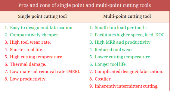
Key points
1) A multi-point cutting tool contains more than two main cutting edges that simultaneously engage in cutting action in a pass.
2) Single Point Cutting Tool is a tool that helps to perform several operations (like Turning, Facing, and Producing Flat surface) on Lathe, Shaper, and Planer Machine. This tool consists of a sharpened cutting part called its point and the shank.
(Two - dimensional cutting)
The cutting edge or face of the tool is perpendicular (900) to the line of action or path of the tool or the cutting velocity vector. This cutting involves only two forces which makes the analysis simpler.
| ORTHOGONAL CUTTING |
Description | The cutting edge of the tool makes the right angle to the direction of feed motion. |
Components of Force | There are only two mutually perpendicular components of force. These components include thrust force, and cutting force, and it can be represented by the 2D coordinate system. |
Tool Life | The tool has a lesser cutting life compared to tools that use oblique cutting. |
Heat Concentration at The Cutting Region | Has a high heat concentration in the cutting region. |
Cutting Edge | The cutting edge is larger than the cutting width. |
Chips Flow | The chips flow is in the direction normal to the cutting edge. |
Shear Force Per Unit Area | The shear force that acts per unit area is high, a factor that increases the heat developed per unit area. |
Surface Finish | The surface finish obtained is poor when compared to oblique cutting which gives a fairly good surface finish. |
Use | Used in parting, grooving, slotting, pipe cutting, etc. |
In orthogonal cutting, the resultant force  which is applied by the tool to the chip lies in a plane normal to the tool cutting edge. This can be determined experimentally by measuring the orthogonal components in the direction of cutting (known as cutting force Fh), and other normal in the direction of cutting (known as thrust force Fv) with the help of dynamometers. The magnitude of the resultant force can be found out as:
R = 
The component of R in the direction of width b is zero.
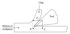
Figure 3: Orthogonal component f cutting force.
The geometrical relationships of components of the resultant force in other directions can be found out with the help of Fig. 3 which shows the following angles, and directions.
Shear plane angle = φ
The angle of friction = β
Tool rake angle = α
The following pairs of components are shown in selected directions.
Fh = Horizontal force component along cutting velocity vector.
FV = Vertical force component normal to cutting velocity vector.
Fs = Force component parallel to shear plane (AC)
Fp = Force component normal to shear plane (AC)
Ft = Force component parallel to tool rake face.
Fn = Force component normal to tool rake face.
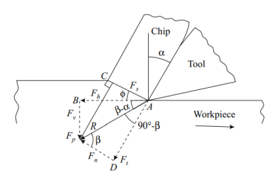
Figure:4 Cutting forces
R = 
R = 
R = 
If the average coefficient of friction between the chip, and the tool is represented by µ.

Also, 
Expressing different force components in term of R, ,
, , and
, and 


Key points:
1) In orthogonal cutting, the resultant force  which is applied by the tool to the chip lies in a plane normal to the tool cutting edge. This can be determined experimentally by measuring the orthogonal components in the direction of cutting (known as cutting force Fh), and other normal in the direction of cutting (known as thrust force Fv) with the help of dynamometers. The magnitude of the resultant force can be found out as:
R = 
A metal cutting process using a single-point cutting tool is shown in Fig. 1. 6. In this process, a wedge-shaped tool moves relative to the workpiece at an angle α. As the tool makes contact with the metal it exerts pressure on it. Due to this pressure exerted by the tooltip, the metal starts to shear in the form of chips on the shear plane AB. A metal chip is produced ahead of the cutting tool by deforming, and shearing the material continuously along the shear plane AB.
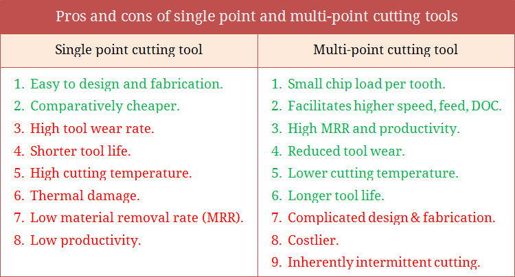
Figure 5: Mechanics of chip formation
Microscopic study indicates that chips are produced by the shearing process. The Shearing process in chip formation is almost similar to the motion of cards in a deck sliding against each other, as shown in Fig. 1. 6. Shearing always takes place along a shear zone (shear plane). The shear plane is a narrow zone that extends from the cutting edge of the tool to the surface of the workpiece.
The shear plane is at an angle called the shear angle (φ), with the surface of the workpiece. The shear zone has a high impact on the quality of the machined surface. Below the shear plane, the workpiece is under formed whereas above the shear plane the chip is already formed, and moving upwards to the tool face.
The ratio of the thickness of the chip before the cut (to) to the thickness of the chip after the cut (tc) is known as the chip thickness ratio. It is generally represented by r, and it is expressed as:

The chip thickness after the cut (tc) is always greater than the chip thickness before the cut (to). The value of r is always less than unity. The reciprocal of r is known as chip compression ratio or chip reduction ratio (1/r).
The chip reduction ratio is a measure of how thick the chip has become when compared to the depth of cut (t0). Thus, the chip reduction ratio(1/r) is always greater than unity.
Shear Plane
Shear Plane Angle
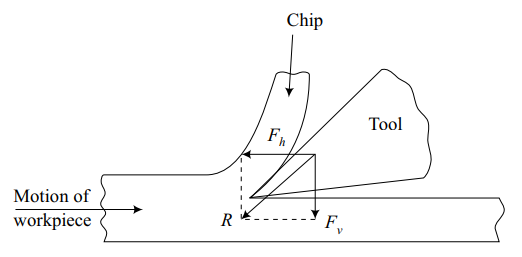
Figure 6: Mechanism of chip formation in orthogonal cutting
Derivation to Calculate Shear Angles
(i) Tool should contact the chip on its rake face.
(ii) Plain strain conditions considered. It means there is no side flow of the chip during cutting.
(iii) The deformation zone is very thin (in the order of 10-2 to 10-3 mm) adjacent to the shear plane AB.
In figure 6 following symbols were used:
α – Rake angle
γ – Clearance (relief) angle
φ – Shear angle
AB – Shear plane
t0 – Uncut chip thickness
tc – Chip thickness (deformed)
Area DEFG – Area of uncut chip
Area HIJK – Chip area after cutting.
From the above figure,


The chip thickness ratio can be expressed as

The chip reduction ratio becomes


This is the required relation to calculate the shear angle (φ). This relation shows that φ depends upon the t0, tc, and α (rake angle). It means by measuring t0, tc, and α of the tool, shear angle (φ) can be determined using the above expression.
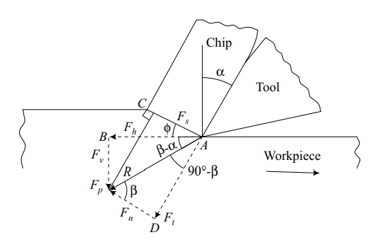
Fig 7
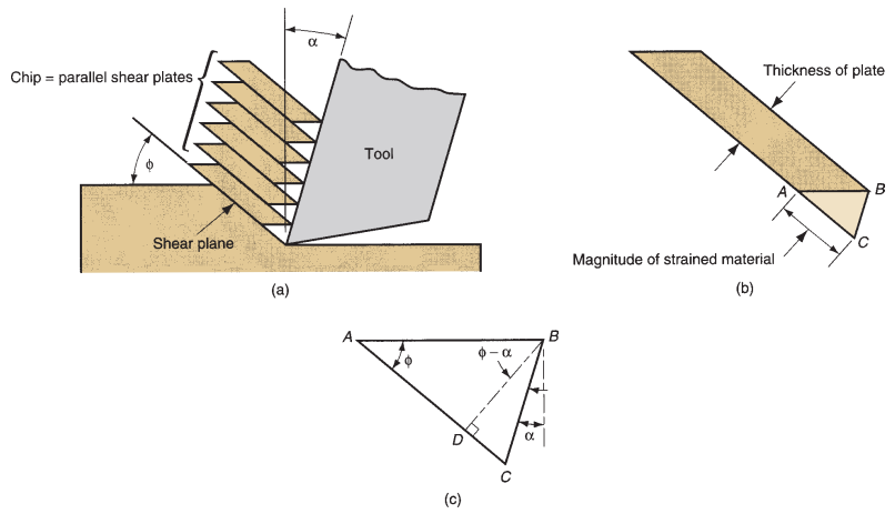
Figure7: Shear strain during chip formation: (a) chip formation depicted as a series of parallel plates sliding relative to each other; (b) one of the plates isolated to illustrate the definition of shear strain based on this parallel plate model, and (c) shear strain triangle
Consistent with the definition of shear strain, each plate experiences the shear strain as shown in Figure 1. 8. Referring to part (c), this can be expressed as

It can be reduced to the following definition of shear strain in the metal cutting process

(i) Cutting Speed or Velocity (V):
Cutting velocity is the velocity of the cutting tool relative to the workpiece.
(ii) Shear Velocity (Vs):
Shear velocity is the velocity of the chip relative to the workpiece. This is the velocity at which shearing takes place.
(iii) Chip Velocity (Vc):
Chip velocity is the velocity of the chip, up the tool face (rake face) during cutting.
Let, V – Cutting Velocity
Vs – Shear Velocity
Vc – Chip velocity
φ – Shear angle
α – Rake angle
r – Chip thickness ratio
γ – Clearance angle
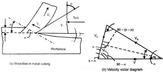
Figure 8: Velocities in Metal Cutting Process
Using the continuity equation, the volume of metal removal before, and after is the same:
V. t = Vc. tc
Vc / V = t / tc = r
Using the sine rule to the velocity vectors we can write:


Similarly, 
Also, 
From kinematics theory, the relative velocity of the two bodies (tool, and chip) is equal to the vector difference between their velocities relative to the reference body (workpiece).
V = VC + VS
Forces Acting on the Chip:
The various forces acting on the chip during the orthogonal metal cutting process is shown in Fig. :
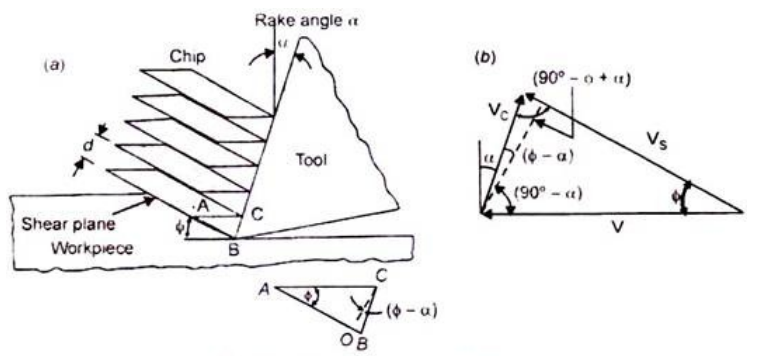
Figure 9: Forces acting on chip
(i) Shear Force (Fs):
The shear force acts along the shear plane. It is the resistance to shear of metal.
(ii) Normal Force (Fn):
The normal force is perpendicular to the shear plane generated by the workpiece.
(iii) Normal Force (N):
It is exerted by the tooltip on the chip.
(iv) Fractional Resistance Force (F):
Fractional resistance force is acting on the chip, and it acts against the chip motion along the tool face.
Fig. 1. 10 (b) indicates the free body diagram of the chip which is in equilibrium under the action of resultant forces which are equal, and opposite in magnitude, and direction.
Thus,

Since, the chip is in equilibrium condition, then

Key points
1) The ratio of the thickness of the chip before the cut (to) to the thickness of the chip after the cut (tc) is known as the chip thickness ratio. It is generally represented by r, and it is expressed as:

2.5.1 Tool wear
Cutting tools are subjected to an extremely severe rubbing process. They are in metal-to-metal contact between the chip, and the workpiece, under high stress, and temperature. The situation becomes severe due to the existence of extreme stress, and temperature gradients near the surface of the tool.
Tool wear is generally a gradual process due to regular operation. Tool wear can be compared with the wear of the tip of an ordinary pencil. According to the Australian standard, tool wear can be defined as “The change of shape of the tool from its original shape, during cutting, resulting from the gradual loss of tool material”.
Tool wear depends upon the following parameters:
i. Tool, and workpiece material.
ii. Tool shape.
iii. Cutting Speed.
iv. Feed.
v. Depth of cut.
vi. Cutting fluid used.
vii. Machine Tool characteristics etc.
Tool wear affects the following items:
i. Increased cutting forces.
ii. Increased cutting temperature.
iii. Decreased accuracy of produced parts.
iv. Decreased tool life.
v. Poor surface finish.
vi. Economics of cutting operations.
Types of Tool Wear:
The high contact stresses are developed in the machining process due to rubbing action of:
(i) Tool rake face, and chips.
(ii) Tool flank face, and machined surface.
These results in a variety of wear patterns observed at the rake face, and the flank face. We call this gradual wear of the tool. The gradual wear is unavoidable but controllable. It is wear which cannot be prevented. It has to occur after a certain machining time.
The gradual wear can be controlled by remedial action. The gradual wear can be divided into two basic types of wear, corresponding to two regions in the cutting tool as shown in Fig. 9. 16.
These are the following:
(i) Flank wear.
(ii) Crater wear.
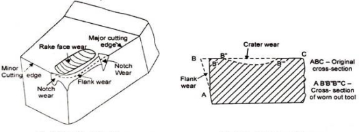
Fig 10 a-Tool wear phenomena b- Flank and crater wear
Tool Wear Phenomena, and Flank, and Crater Wear
(i) Flank Wear:
Wear on the flank face (relief or clearance face) of the tool is called flank wear. The flank wear is shown in Fig.11 (a, b, c).
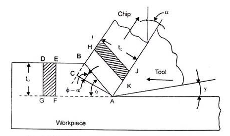
Fig 11
The characteristics of flank wear are the following:
i. It is the most important wear that appears on the flank surface parallel to the cutting edge. It is most commonly results from abrasive/adhesive wear of the cutting edge against the machined surface.
ii. It generally results from high temperatures, which affect tool, and work material properties.
iii. It results in the formation of wear land. Wear land formation is not always uniform along with the major, and the minor cutting edge of the tool.
iv. It can be measured by using the average wear land size (V3), and maximum wear land size (VB max).
v. It can be described using the Tool Life Expectancy Equation.
VCTn = C
A more general form of the equation (considering the depth of cut, and feed rate) is
VcTnDxFy = C
Where
Vc = Cutting Speed
T = Tool life
D = Depth of cut (mm)
F = Feed rate (mm/rev. or inch/rev. )
x, and y = Exponents that are determined experimentally for each cutting condition.
C = Machining constant, found by experimentation or published databook. Depends on the properties of tool materials, workpiece, and feed rate
n = exponential
Values of n = 0. 1 to 0. 15 (For HSS tools)
= 0. 2 to 0. 4 (For carbide tools)
= 0. 4 to 0. 6 (For ceramic tools)
Reasons for Flank Wear:
i. Increased cutting speed causes flank to wear to grow rapidly.
ii. Increase in feed, and depth of cut can also result in larger flank wear.
iii. Abrasion by hard panicles in the workpiece.
iv. Shearing of micro welds between tool, and work-material.
v. Abrasion by fragments of built-up edge, which strike against the clearance face (Flank face) of the tool.
Remedies for Flank Wear:
i. Reduce cutting speed.
ii. Reduce feed, and depth of cut.
iii. Use a hard grade of carbide if possible.
iv. Prevent formation of built-up edge, using chip breakers.
Effects of Flank Wear:
i. Increase in the total cutting force.
ii. Increase in component surface roughness.
iii. Also affects the component dimensional accuracy.
iv. When form tools are used, flank wear will also change the shape of the components produced,
(ii) Crater Wear:
Wear on the rake face of the tool is called crater wear. As the name suggests, the shape of wear is that of a crater or a bowl. The crater wear is shown in Fig. 9. 18 (a, b, c).
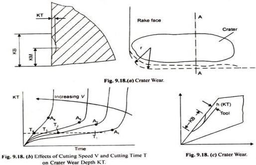
Fig 12
The characteristics of crater wear are the following:
i. In crater wear chips erode the rake face of the tool.
ii. The chips that flow across the rake face develop severe friction between the chip, and the rake face. This produces a scar on the rake face which is usually parallel to the major cutting edge.
iii. It is somewhat normal for tool wear, and does not seriously degrade the use of a tool until it becomes serious enough to cause a cutting edge failure.
iv. The crater wear can increase the working rake angle, and reduce the cutting force, but it will also weaken the strength of the cutting edge.
v. It is more common in ductile materials like steel which produce long continuous chips. It is also more common in H. S. S. (High-Speed Steel) tools than the ceramic or carbide tools which have much higher hot hardness.
vi. The parameters used to measure the crater wear can be seen in Fig. 9. 18. The crater depth KT is the most commonly used parameter in evaluating the rake face wear.
vii. It occurs approximately at a height equal to the cutting depth of the material, i. e. , Crater wear depth ⋍ cutting depth.
viii. At high-temperature zones (nearly 700°C) create wear occurs.
Reasons for Crater Wear:
i. Severe abrasion between the chip-tool interfaces, especially on the rake face.
ii. High temperature in the tool-chip interface.
iii. Increase in feed results in an increased force acting on the tool interface, this leads to a rise in temperature of the tool-chip interface.
iv. Increase in cutting speed results in increased chip velocity at the rake face, this leads to a rise in temperature at the chip-tool interface, and so an increase in crater wear.
Remedies for Crater Wear:
i. Use of proper lubricants can decrease the abrasion process, and so decrease crater wear.
ii. Proper coolant for rapid heat dissipation from the tool-chip interface.
iii. Reduced cutting speeds, and feed rates.
iv. Use tougher, and hot hardness materials for tools.
v. Use positive rake tool.
Causes of Tool Wear:
There are large numbers of causes for tool wear.
Some of them are important to discuss here from the subject point of view:
(i) Abrasive wear (Hard particle wear).
(ii) Adhesive wear.
(iii) Diffusion wears.
(iv) Chemical wear.
(v) Fracture wear.
(i) Abrasive Wear (Hard Particle Wear):
Abrasive wear is caused by the impurities within the workpiece material, such as carbon nitride, and oxide compounds, as well as the built-up edge fragments. It is a mechanical type of wear. It is the main cause of the tool wear at low cutting speeds.
(ii) Adhesive Wear:
Due to high pressure, and temperature at the tool-chip interface, there is a tendency of hot chips to weld onto the tool rake face. This concept leads to the subsequent formation, and destruction of welded junctions. When the weld intermittently breaks away picking particles of the cutting tool. This leads to crater wear. Fig. 9. 19 shows adhesive wear.
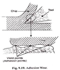
Fig 13
(iii) Diffusion Wear:
Diffusion wear is usually caused by atomic transfer between contacting materials under high pressure, and temperature conditions. This phenomenon starts at the chip-tool interface. At such elevated temperatures, some particles of tool materials diffuse into the chip material. It can also happen that some particles of work material also diffuse into the tool materials.
This exchange of particles changes the properties of tool material, and causes wear, as shown in Fig. 9. 20:
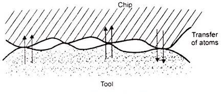
Fig 14 Diffusion wear
This diffusion results in changes in the tool, and workpiece composition.
There are several ways of diffusions like:
(a) Gross Softening of the Tool:
Diffusion of carbon in a relatively deep surface layer of the tool may cause softening, and subsequent plastic flow of the tool. It may produce major changes in tool geometry.
(b) Diffusion of Major Tool Constituents into the Work:
The tool matrix or a major strengthening constituent may be dissolved into the work, and chip surfaces as they pass the tool. For example Demand tool, cutting iron, and steel is the typical examples of carbon diffusion.
(c) Diffusion of a Work Material Component into the Tool:
A constituent of the work material diffusing into the tool may alter the physical properties of a surface layer of the tool. For example, The diffusion of lead into the tool may produce a thin brittle surface layer, this thin layer can be removed by chipping.
(iv) Chemical Wear:
The chemical wear is caused due to a chemical attack on a surface.
For example:
Corrosive wear.
(v) Facture Wear:
The facture wears usually caused by breaking off the edge at the end or length. The bulk breakage is the most harmful, and undesirable type of wear, and it should be avoided as far as possible.
Growth of Tool Wear:
The growth pattern of tool wear is shown in Fig. 15:
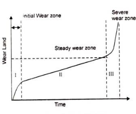
Fig 15 Growth of tool wear
We can divide the growth into the following three zones:
(i) Severe wear zone.
(ii) Initial Wear zone.
(iii) Severe or ultimate or catastrophic wear zone.
(i) Initial Preliminary or Rapid Wear Zone:
Initially, for the new cutting edge, the growth of wear is faster. The initial wear size is VB = 0. 05 to 0. 1 mm normally.
The causes of initial or rapid wear are:
i. Microcraking.
ii. Surface oxidation.
iii. Carbon loss layer.
iv. Micro-roughness of tooltip grinding.
(ii) Steady Wear Zone:
After the initial wear, we found that the wear rate is relatively steady or constant. In this zone, the wear size is proportional to the cutting time.
(iii) Severe or ultimate or catastrophic Wear Zone:
In this zone, the rate of growth of wear is much faster and result in catastrophic failure of the cutting edge.
When the wear size increases to a critical value, the surface roughness of the machined surface decreases, cutting force, and temperature increases rapidly, and the wear rate increases. Then the tool loses its cutting ability. In practice, this zone of wear should be avoided.
Allowable Wear Land:
As we decide to sharpen a knife-edge when the quality of the cut begins to deteriorate, and the cutting forces required increase too much, similarly re-sharpen or replace cutting tools when.
(a) The quality of the machined surface begins to deteriorate.
(b) The cutting forces increase significantly.
(c) Pre-temperature rise significantly.
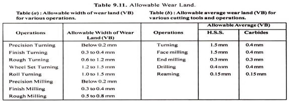
The average width of allowable flank wear varies from 0. 2 mm (for a precision turning operation) to 1 mm (for a rough turning operation).
The following Table 9. 11 gives some recommended values of allowable average wear land (VB) for various operations, and cutting tools:
Forms of Tool Wear:
Flank and crater wear is a very common type of wear.
Some other forms of tool wear are:
(i) Thermo-Electric Wear.
(ii) Thermal Cracking, and Tool Fracture.
(iii) Cyclic Thermal, and Mechanical Load Wear.
(iv) Edge Chipping.
(v) Entry or Exit Failures.
(i) Thermo-Electric Wear:
It can be observed in the high-temperature region. The high-temperature results in the formation of a thermal-couple between the workpiece, and the tool.
Due to this effect voltage established between the workpiece, and tool. It may cause an electric current flow between the two. However, this type of wear has not been developed.
(ii) Thermal Cracking, and Tool Fracture:
It is common in the case of the milling operation. In milling, tools are subjected to cyclic thermal, and mechanical loads. Teeth may fail by a mechanism not observed in continuous cutting. Thermal cracking can be reduced by reducing the cutting speed or by using a tool material grade with higher thermal shock resistance.
(iii) Cyclic Thermal, and Mechanical Load Wear:
The cyclic variation in temperature in the milling process induces cyclic thermal stress at the surface layer of the tool expands and contracts. It may lead to the formation of thermal fatigue cracks near the cutting edge.
Mostly, such cracks are perpendicular to the cutting edge, and begin formation at the outer corner of the tool, spreading inward as cutting progress. The growth of these cracks eventually leads to edge chipping or tool breakage. An insufficient coolant can promote crack formation.
(iv) Edge Chipping:
Edge chipping is commonly observed in milling operations. It may occur when the tool first contacts the part (Entry Failure) or, more commonly, when it exits the part (Exit Failure).
(v) Entry or Exit Failures:
Entry failure most commonly occurs when the outer corner of the insert strikes the part first. This is more likely to occur when the cutter rake angles are positive. Entry failure is therefore most easily prevented by switching from positive to negative rake angle cutters.
Consequences (Effects) of Tool Wear:
The effects of the tool wear on technological performance are the following:
(i) Increase in Cutting Forces:
The cutting forces are normally increased by the wear of the tool. Crater wear, flank wear (or wear land formation), and chipping of cutting edge affect the performance of the cutting tool in various ways. Crater wear may, however under certain circumstances, reduce forces by effectively increasing the rake angle of the tool. Clearance face (Flank or wear-land) wear, and chipping almost invariably increase the cutting forces due to increased rubbing forces.
(ii) Increase in Surface Roughness:
As the tool wear increases, the surface roughness of the machined component also increases. This is particularly true for a tool worn by chipping. Although, there are circumstances, in which a wear land may burnish (polish) the workpiece, and produce a good finish.
(iii) Increase in Vibration or Chatter:
Vibration or chatter is another important aspect of the cutting process which may be influenced by tool wear.
A wear land increases the tendency of a tool to dynamic instability or vibrations. When the tool is sharp, the cutting operation is quite free of vibrations. On the other hand, when the tool wears, the cutting operation is subjected to an unacceptable vibration, and chatter mode.
(iv) Decreases in Dimensional Accuracy:
Due to flank wear, the plan geometry of a tool may disturb. This may affect the dimensions of the component produced. It may influence the shape of the component.
2. 5. 2 Tool life
Every device or tool has its functional and expected life of work. At the expiry of which it may still be operational, but not efficiently. During its usage, the tool losses its material, i. e. , it gets worn out. As the wearing of the tool increases, the tool starts to lose its efficiency. Therefore, its life has to be defined, and on the expiry of its life, it should be reground for fresh use.
The tool life can be defined as:
(i) The time elapsed between two successive grindings.
(ii) The period during which a tool cuts satisfactorily.
(iii) The total time duration accumulated before tool failure occurs.
Tool life is expressed in minutes.
The relation between cutting speed, and tool life can be obtained by Taylor’s tool life equation:
VTn = C
Methods for Tool Life Measurements:The most commonly used methods for tool life measurements are:
(i) Machining Time:
The elapsed time of operation of the machine tool.
(ii) Actual Cutting Time:
The time during which the tool cuts.
(iii) A fixed size of Wear Land on Flank Surface:
On carbide and ceramic tools where crater wear is negligible, tool life can be taken as corresponding to 0. 038 or 0. 076 mm of wear land on the flank surface for finishing respectively.
(iv) Volume of metal removed.
(v) Number of pieces machined.
The tool life between replacement and re-conditioning can be defined in several ways, as:
(a) Actual cutting time is taken to failure.
(b) Volume of metal removed to failure.
(c) Number of parts produced to failure.
(d) Cutting speed for a time to failure.
(e) Length of work machined to failure.
Tool Life Expectancy (Taylor’s Tool Life Equation):
VCTn = C
VcTnDxFy = C
Where, KC = Cutting speed (m/min)
T = Tool life (min)
D = Depth of cut (mm)
F = Feed rate (mm/rev)
x, y = Exponents, which are determined experimentally for each cutting condition.
n = Exponent, that depends on tool materials.
Value of n = 0. 1 - 0. 2; for H. S. S. tools
0. 2 -0. 4; for Carbide tools
0. 4 - 0. 6; for Ceramic tools
C = Machining constant, computed by experimentation or published data-book. It depends on the properties of tool material, workpiece, and feed rate.
Observations from the Tool Life Equation:
i. Tool life decreases with an increase in the cutting speed.
ii. Tool life also depends to a great extent on the feed rate (F), and depth of cut (D).
iii. Decrease of tool life with increased speed is twice as great as the decrease of life with increased feed.
iv. The greatest variation of tools life is with cutting speed, and tool temperature which is deeply related to cutting speed.
Tool Life Criteria (Criteria for Judging Tool Failure):
The following are some criterion for judging tool life/failure:
(i) Complete failure.
(ii) Flank or crater failure.
(iii) Finish failure.
(iv) Size failure.
(v) Cutting force failure.
(i) Complete Failure:
(ii) Flank or Crater Failure:
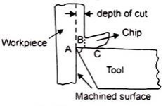
Fig 16 Flank failure
(iii) Finish Failure:
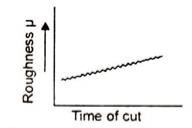
Fig 17 Finish failure
(iv) Size Failure:
(v) Cutting Force Failure:
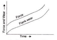
Fig 18 Cutting force failure
Factors Affecting Tool Life:
The following factors play an important role in tool life:
(i) Cutting speed.
(ii) Feed rate, and Depth of cut.
(iii) Hardness of workpiece.
(iv) Microstructure of workpiece.
(v) Tool material.
(vi) Tool geometry.
(vii) Type of cutting fluid, and its method of application.
(viii) Nature of cutting.
(ix) Grain size of the workpiece.
(x) Rigidity of workpiece machine-tool system.
(i) Cutting Speed:
VCTn = C
Where V= Cutting speed (m/min)
T= Tool life (min) C = Constant or machining constant
n = Tool life index. It depends on the tool, and work material combination, and cutting conditions.
If T = 1 min
then C = Vc
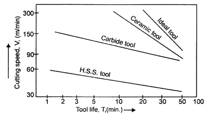
Fig 19 Tool life plots for various tool materials
(ii) Feed Rate, and Depth of Cut:

 (For cemented carbide tool)

(iii) Hardness of Workpiece:

where,
Hb = Brinell hardness number of work material
Ψ = Percentage reduction
V = Permissible cutting speed for a given tool life
(iv) Microstructure of Workpiece:
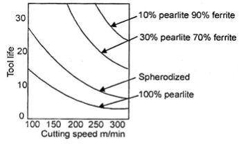
Fig 20 Effect of microstructure of work material on tool life
(v) Tool Material:
Some tool materials with their properties are the following:
i. Carbon Sleets:
ii. H. S. S. :
iii. Cemented Carbide:
iv. Sintered Oxides or Ceramics:
(vi) Tool Geometry:
(a) Back Rake Angle.
(b) Principal Cutting Edge.
(c) Clearance Angle.
(d) Nose Radius.
(a) Back Rake Angle:
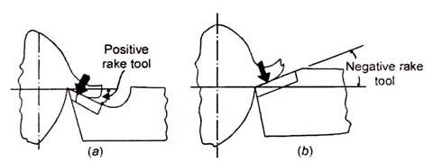
Fig 21 Cutting process using positive and negative rake tools
(b) Principal Cutting Edge:
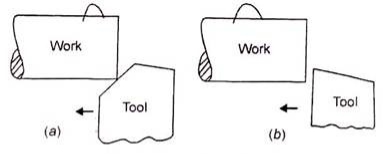
Fig 22 Principal cutting edge
(c) Clearance Angle:
(d) Nose Radius:
A relationship between cutting speed, tool life, and nose radius are given below:
VT0. 09 = 300R0. 25
Where, R = Nose radius (for H. S. S. tool cutting SAE-2346 steel)
T= Tool life (min)
V = Cutting speed (m/min)
(vii) Type of Cutting Fluid, and its Method of Application:
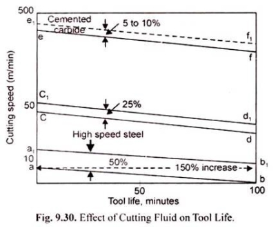
(viii) Nature of Cutting:
(ix) Grain Size of Workpiece:
(x) Rigidity of Workpiece-Machine Tool System:
Key points
1) The relation between cutting speed, and tool life can be obtained by Taylor’s tool life equation:
VTn = C
2) A more general form of the equation considering the depth of cut, and feed rate is given as
VcTnDxFy = C
Where, KC = Cutting speed (m/min)
T = Tool life (min)
D = Depth of cut (mm)
F = Feed rate (mm/rev)
x, y = Exponents, which are determined experimentally for each cutting condition.
n = Exponent, that depends on tool materials.
Value of n = 0. 1 - 0. 2; for H. S. S. tools
0. 2 -0. 4; for Carbide tools
0. 4 - 0. 6; for Ceramic tools
C = Machining constant,
The functional performance of any solid surface relies on the physical conditions, and chemical composition of the concerned surface, and subsurface layers. Quality is defined as a fit for the intended purpose. Similarly, the quality of a solid surface is one subjective matter, and its assessment primarily depends on intended functionalities. Let us explain the same with examples. With respect to the decorative artifact, the appearance of the surface has importance rather than the presence of micro-cracks on the surface or sub-surface (such cracks can be easily filled by good quality coating or coloring). However, if we consider one metallic structural member then strength, hardness, anti-corrosiveness, etc. become dominating factors, and consequently, the presence of cracks, micro-cracks, holes, defects, etc. determines the surface quality of the concerned structural member.
These are three terms, namely surface roughness, surface finish, and surface integrity, which are commonly used to define the quality of the surface of the manufactured product. Sometimes they are used interchangeably, but they are not the same. Roughness and finish imply the same thing but in a different way; whereas integrity has a broad domain, and encompasses the former two. Their differences with respect to manufactured products are discussed in the following sections.
What is the surface finish? How it is related to surface roughness?
The smoothness of a surface is determined by the surface finish. It indirectly indicates the height, and depth of asperities of the solid surface. No surface is perfectly smooth; even if it is perfectly smooth, it cannot be determined as every measuring instrument has a range of its capability. Looking on a surface in the bare eye may not reveal asperities; however, a magnified view of a solid surface will reveal such peaks, and valleys, as shown below for a surface after grinding (abrasive finishing).
 Fig 23
Plot of variation of surface roughness (micron) against length (mm) for a typical ground surface.
Surface roughness is the quantitative approach of determining the smoothness of a surface by measuring the height of such peaks, and depth of such valleys over a fixed length. There are various principles of measuring roughness; however, all follow the aforementioned basic approach. For example, average surface roughness (Ra), 10 point average (R10), root means square (Rz), etc. Whatever be the case, roughness can quantitatively determine the profile of a solid surface and is one crucial parameter of surface texture. A particular manufacturing process can provide a certain level of roughness, and therefore machining (surface modification) process should be selected based on the intended roughness. Usually, secondary manufacturing processes, such as machining, tend to provide a smoother surface. There also exist many processes (like lapping, buffing, superfinishing, ion beam machining, etc. ) that are exclusively used to reduce the surface roughness of a component rather than bulk removal of material.
Unlike surface roughness, surface finish is one qualitative approach to indicating the smoothness of a surface. Roughness and finish are inversely proportional. Thus lower the roughness, the better is the finish. Attributes like poor, bad, good, fine, smooth, etc. are used to express surface finish rather than an exact numerical value (like 100nm). Thus it is affected by human bias. It is worth mentioning that roughness and finish are localized factors, and don’t take care of the entire surface. There are many other surface profile parameters such as waviness, texture, etc. for the same.
What is surface integrity? Which parameters come under this?
Surface integrity encompasses all of the elements that describe all conditions of an existing solid surface. It takes care of not only surface topography but also metallurgical aspects of the surface, and sub-surface. The concept of surface integrity was introduced by Field, and Kahles in 1964, and they defined surface integrity as the inherent or enhanced condition of a surface produced in machining or other surface generation operation. Every surface generation or modification process is associated with the alteration of various properties including roughness, plastic deformation, micro-cracking, phase transformations, micro-hardness, residual stress, etc. Thus surface integrity takes care of such alteration.
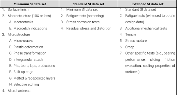
There exist a standard dataset for surface integrity (SI) prepared by Field et al. (1972) as given below. Surface finish is one important factor that comes under this data set. The finish is the first, and foremost parameter in the integrity data set.
Set-1: Minimum SI data set (MDS)
- Macro cracks
- Macro etch indications
- Microcracks
- Plastic deformation
- Phase transformation
- Intergranular attack
- Pits, tears, laps, protrusions
- Built-up edge
- Melted, and redeposited layers
- Selective etching
Set-2: Standard SI data set (SDS)
Set-3: Extended SI data set (EDS)
How surface finish differs from surface integrity?
Surface finish is one parameter of surface topography that indicates the smoothness of a solid surface. It is one qualitative approach to designating the quality of a surface of the manufactured product. On the other hand, surface integrity has a broad domain and consists of all surface topography parameters as well as surface, and sub-surface metallurgical parameters. Integrity encompasses surface finish, micro-crack, plastic deformation, phase transformation, melted, and redeposit layers, microhardness, residual stress, distortion, creep, etc. Therefore, the surface finish is just one element of the surface integrity set.
Machinability can be defined as the ease with which a material can be machined. Machinability depends on the physical properties and the cutting parameters of the material.
Machinability is a term indicating how the work material responds and reacts to the cutting process. In the most general cases, good machinability indicates that material is cut with good surface finish, less force, long tool life, and power requirements, and low cost.
Materials with good machinability require minimum power to cut. They can be cut quickly, easily obtain a good surface finish, and do not wear the tool much. Such materials are known to be free machinable.
Machinability can be difficult to predict exactly because the machining process has a lot of variables. Strong, tough materials are usually more difficult to machine because the greater force is required to cut them.
Other important factors that affect machinability include:
i. Work parameters (chemical composition, microstructure hardness)
ii. Tool parameters (tool geometry, tool life, tool material)
iii. Machining parameters (cutting speed, feed, depth of cut, lubrication, etc. )
It is stated that material A is more machinable than material B, this can have three different meanings;
Lower wear rate is obtained with material A, or
Better surface finish can be achieved with material A or
Less power is required to machine material A.
Therefore, it is of great importance to note that machinability is always defined with a particular set of conditions.
Factors Affecting Machinability:(i) Work material parameters.
(ii) Tool parameters.
(iii) Machining parameters.
(i) Work Material Parameters:
It includes:
i. Hardness.
ii. Microstructure.
iii. Chemical composition.
iv. Shape, and dimensions.
v. Rigidity of holding.
vi. Tensile strength.
(ii) Toot Parameters:
It includes:
i. Tool geometry.
ii. Tool material.
iii. Rigidity of tool holding.
iv. Selection of proper tool.
v. Tool grinding process.
vi. Temperature of chip tool interface.
(iii) Machining Parameters:
It includes:
i. Cutting speed.
ii. Feed.
iii. Depth of cut.
iv. Cutting fluid.
v. Nature of cutting process (Intermittent or steady).
vi. Rigidity of work-tool holding.
vii. Ease of chip disposal.
Machinability of different materials
Other metals
Key points
1) Machinability can be defined as the ease with which a material can be machined. Machinability depends on the physical properties and the cutting parameters of the material.
Commonly machined materials include plastics, aluminum, many varieties of steels including heat-treated tool steels that are as hard as a knife blade, ceramics, and many others. Cutting tools must be capable of retaining their hardness at high temperatures (hot hardness).
A variety of cutting tool materials are needed. Some must be very hard for long tool life, and to machine hard workpiece materials. Others must be very shock resistant (tough) to withstand interrupted cuts (intermittent cutting action).
The major requirements of cutting tool materials are: Hot hardness, impact toughness, and wear resistance. For better tool life, the material must have the above properties. It is very clear from the figure; at any cutting speed, the tool life is maximum for ceramic tool, and lowest for the high-speed steel tool. So, using a ceramic tool maximum volume of material could be removed at any cutting speed for specific tool life.
An ideal tool material will have n = 1 (Taylor’s tool life index). It means ideal material tool at all cutting speeds, removes the maximum volume of work material.
Some tool materials with their properties are the following:
i. Carbon Sleets:
ii. H. S. S. :
iii. Cemented Carbide:
iv. Sintered Oxides or Ceramics:
i. Plastic deformation of the metal at shear zone.
ii. Friction between chip, and rake surface of the tool.
iii. Rubbing action between work, and the flank surface of the tool.
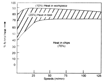
Fig 24 heat generation in cutting process
The main functions of cutting fluids used in the machining process are:
1. For Heat Dissipation:
To dissipate the heat generated during machining cutting fluids are used.
2. To Cool the Workpiece:
To cool the workpiece by carrying away the heat by coolant.
3. To Cool the Tool:
To cool the cutting tool by cooling down the cutting zone.
4. To Reduce Friction, and Wear:
To reduce the friction, and wear of the tool with the help of lubricants.
5. To Reduce Forces and Energy Consumption:
It decreases the power consumption in cutting the material, by reducing wear.
6. To Improve the Tool Life:
By dissipating the heat generated properly.
7. To Improve the Surface Finish:
By carrying away the heat from work material.
8. To Flush Away the Chips:
To keep the cutting zone free from hot chips, and to cause chips to break up into small parts.
9. To Protect Machined Surface from Environmental Corrosion:
Corrosion inhibitors like triethanolamine or sodium nitrate are added to the cutting fluids to prevent corrosion of the machined surface.
Desirable Properties of Cutting Fluid:
1. Lubricating Qualities:
This quality reduces frictional force between the workpiece and the tool. It also prevents the formation of a built-up edge on the workpiece.
2. High Heat Carrying (Cooling) Capacity:
Cutting fluid must carry maximum heat from the cutting zone quickly. Thus reducing the temperature of the workpiece, and the tool. This will reduce tool wear, increase tool life, and surface finish of the work.
A small reduction in temperature can considerably increase the tool life, according to the following empirical relation:
Tθn = K
Where T= Tool life (min)
θ = Temperature at the chip tool interface (°C)
n = An exponent that depends on tool form, and material
K = Constant
3. Corrosion Resistant:
The cutting fluid must prevent the work material from environmental rusting or corrosion. For this purpose, corrosion inhibitor like sodium nitrate along with other additives is added to the cutting fluid.
4. Low Viscosity:
It must have low viscosity; so that chip and dirt can settle quickly.
5. Stability:
It must have a long life; it should not get spoiled quickly, both in use and in storage.
6. Non-Toxic:
It must be non-toxic, and should not be injurious to the human skin.
7. Non-Flammable:
It must have a high flash point, and should not burn easily.
8. Non-Smokey:
It must not smoke or foam easily.
9. Small Molecular Size:
It must have a small molecular size to allow rapid diffusion and better penetration to the chip-tool interface.
10. Chemically Stable or Inert:
It must not adversely react with the work material.
11. Odorless:
It must be free from undesirable odors.
Types of Cutting Fluids:
A variety of cutting fluids are readily available to satisfy the requirements of machining processes. Although there is no specific all-purpose cutting fluid, some offer considerable versatility while some are for a specific application.
The basic types of cutting fluids are the following:
1. Water:
Water has high specific heat but it is poor in lubrication. Also, it encourages the rusting of metal parts. It is usually used as a cooling agent during tool grinding.
2. Soluble Oils (Emulsions):
Soluble oils or emulsifiable oils are the most common type of cutting fluids used in machining operations.
These are composed of:
i. Soluble oil.
ii. Emulsifiers (Sodium sulfonate, fatty acid, acid soap, esters).
iii. Additives (Corrosive resistance or coupling agents).
iv. Water (for dilution purpose 1-20%).
Emulsifiers are chemical substances that cause the suspension of very small oil droplets in the water. Additives are coupling agents or corrosive resistance chemicals. The coupling agent provides a white emulsion with no oil or cream, separating after mixing with water 5% dilution level being the most common dilution level. These fluids have average lubrication abilities and better cooling properties. Soluble oils are generally suitable for light cutting operations on general-purpose machines where low metal removal rates are used.
3. Mineral Oils:
Mineral oils are generally used for heavier cutting operations because of their good lubricating properties. They are commonly found in production machines where very high metal removal rates are employed. They are most suitable for steels but they must not be used on copper or its alloys since it has a corrosive effect.
4. Straight Oils (Vegetable Oils or Petroleum):
Straight oil is a vegetable or petroleum oil that is used without dilution with water. Naphthenic oils, Paraffin oils, vegetable oils are some examples of straight oils. Straight oil provides excellent lubrication. Considering environmentally favorable requirements, vegetable oils are preferable due to their ease of biodegradation, and disposal. On the other hand, they are of less use since they are liable to decompose and smell bad.
5. Synthetic Fluids:
Synthetic Fluids are water-based fluids that contain no mineral oil. They have a particulate size of 0. 003 mm. Water content in the synthetic fluid provides excellent cooling properties. But creates an issue of corrosion so it is not effective as a lubricant. To prevent rust formation, rust inhibitors are added.
6. Semi-Synthetic Fluids:
Some major advantages are:
i. Rapid heat dissipation.
ii. Bio-resistance (due to small particle size).
iii. Cleanliness of the system.
2. 10. 1 Coating process
There are two primary processes in place for coating cutting tools: CVD (Chemical Vapor Deposition), and PVD (Physical Vapor Deposition). Each of the methods has its advantages and disadvantages.
CVD coating was the original, and most commonly used coating method for many years. The CVD method involves heating the substrate within a chemical reactor and exposing the substrate to a gas stream. The gases break down on the hot substrate surface, forming a coating layer. In general, the CVD method requires temperatures around 1,000 degrees C.
A common coating uses the three gases TiCL4 (titanium tetrachloride), H2 (hydrogen), and N2 (nitrogen) to produce TiN (titanium nitride) + HCl (Hydrogen Chloride). The HCl is a bi-product of the process and must be disposed of according to strict environmental regulations.
The advantages of the CVD method include optimal layer adhesion, as well as consistent layer distribution. The disadvantages of the CVD method are high temperatures affecting the substrate, few suitable materials for coating as the coating material is fed in a gaseous form and long cycle times.
PVD coating is the newer of the tool coating methods and is becoming increasingly popular in the industry. The PVD method involves transporting laminate material in a vacuum from a source via a transport space to the substrate. The laminate material is vaporized using either thermal or electrical energy from the power source, which then allows the vaporized material to adhere to the substrate.
The advantage of the PVD process is the range of suitable materials for coating, relatively low operating temperatures, around 450° C, allowing for coating of sharp cutting edges. The disadvantages are that coating of internal surfaces is difficult (coating requires a line of sight from the laminate material to the substrate), and the surface requirements of the substrate are much higher.
With PVD, there are two primary technologies used to coat the different substrates: the arc method (arc discharge), and the sputtering method (cathodic sputtering). Both methods share one additional advantage; the coating chambers are relatively easy to construct.
The arc method involves an electrical power source (much like a lightning bolt) hitting the laminate material, and transforming this material from a solid to a liquid to a gaseous phase.
The arc method involves an electrical power source (much like a lightning bolt) hitting the laminate material, and transforming this material from a solid to a liquid to a gaseous phase. The advantage of this process is high layer rates (in relation to sputtering). However, since the laminate material is in all three phases (solid, liquid, and gas) the potential for droplets (minute liquid particles) occurs. These droplets do not achieve a gaseous state.
The sputtering method involves a thermal energy source, which transforms the solid laminate immediately to a gaseous state. No droplets occur as the material skips the liquid phase. However, the lower layer rates (in relation to arc), results in longer cycle times.
Most hard materials (coating is a hard material) consist of a metal, and a metalloid. Some examples of cutting tool’s familiar coatings are TiN (titanium nitride), TiCN (titanium carbonitride), TiAlN (titanium aluminum nitride), AlTiN (aluminum titanium nitride), and AlCrN (aluminum chromium nitride). The periodic table of elements shows the inventory of metals and the metalloids that are potential candidates for coatings.
During the coating process, the smaller metalloid—in the case of TiN, the nitrogen or N—lodges itself in the lattice vacancies of the metal titanium (Ti). When switching to TiCN, the carbon (C) partially replaces some of the nitrogen (N). Following the same logic, the metals, and metalloids required for the other sample coatings can be determined.
This is one of the advantages of the PVD process. Since the metal is solid in the PVD chamber (CVD introduces in a gaseous phase), almost any metal is used for coating. Of course, not all metals are beneficial, but they are available for use.
Through the years of development coating, layer structures have undergone many changes and improvements. There are generally five different layer structures in coating technology.
The monolayer structure, as the name suggests, is only one layer of coating. While looking at the structure under a microscope, tall columns of coating are visible. This is easy to apply, but it also is easy to crack, and damage. Imagine a ball hitting a bunch of columns. The columns will start to fall, and the crack will easily penetrate the substrate.
The multilayer structure is many different monolayer structures on top of each other. Damascene steel is a historical example of this type of structure that combines the properties of several materials to make a surface that is both tough and hard.
Nano layer structures are the same as multilayer, but substantially smaller; the layers are at the atomic level of thickness.
Nanocomposite coatings use similar technology as carbide cutting tools. The Nanostructure combines the toughness of the binder phase (cobalt as an example with carbide) with the hardness of the nanocomposite coating.
The gradient structure gets its capabilities by starting soft, and elastic at its core, and then near the surface, it becomes hard and wear-resistant.
Quality Control, and Inspection of Coatings
After coating the cutting tools, as required in every step of the manufacturing process, the manufacturer needs to perform a quality inspection on the coatings themselves. The quality inspection process and procedure normally involve four areas of inspection layer thickness, layer adhesion, layer construction, and structure, and layer composition, and distribution.
Inspecting layer thickness There are two primary methods for doing this: checking by Calotte grinding or using X-ray fluorescent radiation.
Calotte grinding involves using a small diamond grinding wheel (ball) that grinds away the coating to reveal the substrate below.
Calotte grinding involves using a small diamond grinding wheel (ball) that grinds away the coating to reveal the substrate below. Then, by viewing the ground away area by a microscope, the layer thickness can be measured using the formula (XxY)/ball diameter. Where X is the coating width from a top view, and Y is the substrate plus the coating width from a top view. The goal is to have the achieved value with the coating thickness range the manufacturer specifies.
X-ray fluorescent radiation can be a more accurate methodology as both the coating, and the substrate material produce X-ray fluorescence radiation, but the coating weakens the substrate’s radiation. The degree of weakness of the substrate’s radiation is measured by the secondary emissions, and therefore, determining the coating thickness. A preferred method is Calotte grinding, as it is easier to see, feel, and touch.
Layer adhesion. Once the layer thickness is in tolerance, the next check is layer adhesion. This is probably the most subjective of the quality control tests. Rockwell indentation and the scratch test are the two methods for checking layer adhesion.
Rockwell's indentation involves exactly what it sounds like. A hardened ball is pulled down onto the coated substrate at a set force. The coated substrate cracks and the inspectors review the cracks at the indentation point via a microscope and evaluate the number and intensity of the cracks. Dependent upon the individual criteria set forth by the manufacturer, the inspector determines if it is acceptable or if it fails inspection. While this seems straightforward, the coating thickness also affects the number, and intensity of the cracks, so a thicker coating would allow more cracks than a thinner coating.
The scratch test is a bit more direct. In the scratch test, the inspector places an indenting tool under an increasingly progressive load across the cutting tool. At the critical load Lc, the coating starts to crack. At this point, the distance traveled is measured, and if far enough, the adhesion is acceptable.
Layer construction, and structure. With the thickness good, and the adhesion acceptable, the next step is to review the layer construction, and structure. This is reviewed in the same manner as the layer thickness by calotte grinding. Using the same ball, the coating ground away and viewed under a microscope. Here is where the different layer structures mentioned above are visible and can be confirmed.
Layer composition, and distribution. The last quality control check is the layer composition and distribution. This requires a scanning electron microscope, and energy dispersive X-ray technology (SEM/EDX). The SEM produces an extremely high magnification of images (as much as 200,000×) at high resolution combined with the EDX analysis to determine the materials, and amounts of material in a small section of material (as small as 2 nanometers).
The last portion of an insight into the production of cutting tool coatings is where the coating takes place. There are tremendous advantages of coating the tool in house versus using an outside source; however, coating in-house does require a substantial capital investment.
The advantages of in-house coatings are logistics, processing time, and quality.
Logistically, a manufacturer does not have to package a product for coating nor is shipping required. This will usually save a minimum of two working days. Not only is there a reduction in processing time, but there’s the added advantage of being able to react to bottlenecks in production, and provide less than 24-hour door to door time.
Another advantage is in the quality of the coating. Manufacturers performing coating operations in the house can use product-specific racking and pretreatment. They can ensure there are homogenous batches with no product mix. Therefore, tolerances can be reduced when coating a product in-house.
An outside coating source may have multiple types of products within a coating furnace, and they may have a total tolerance band of 2 to 4 microns for the coating. In-house coating, with homogenous batches, would allow a tolerance band of ± 20 percent from nominal size. If 2 microns were nominal, the coating would have a total tolerance of 0. 8 microns (versus 2 microns). The layer thickness distribution resembles a bell curve, so 81 percent of the product would have a total tolerance of 0. 4 microns.
There is a lot of time, energy, science, and thought that enters into the coating of a cutting tool. A cutting tool manufacturer’s goal is to provide a product to help the user produce their parts faster, and more accurately.
Hopefully, this helps provide some insight into the coating production process and serves as a reminder that there is some serious technology behind that pretty gold insert.
2. 10. 2 Turning process
Turning is the most important machining process and can produce a wide variety of parts. Primarily, turning is used to produce parts cylindrical in shape by a single point cutting tool on lathes. The cutting tool is fed either linearly in the direction parallel or perpendicular to the axis of rotation of the workpiece, or along a specified path to produce complex rotational shapes. The primary motion of cutting in turning is the rotation of the workpiece, and the secondary motion of cutting is the feed motion.
Lathes generally are considered to be the oldest member of machine tools, having been first developed in the late eighteenth century. The most common lathe is called an engine lathe because it was one of the first machines driven by Watt’s steam engine. The basic lathe has the following main parts: bed, headstock, tailstock, and carriage. The types of lathes available for a variety of applications may be listed as follows: engine lathes, bench lathes, horizontal turret lathes, vertical lathes, and automatics. A great variety of lathes and attachments are available within each category, also depending on the production rate required.
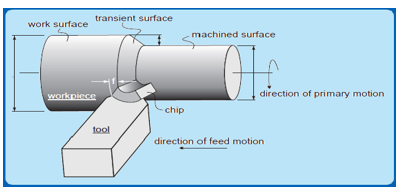
Fig 25
The major subtypes of turning are:
Straight turning: It is used to reduce the diameter of a part to the desired dimension. The resulting machined surface is cylindrical.
Contour turning, and Taper turning: These are performed by employing a complex feed motion using special attachments to a single point turning tool thus creating a contoured shape on the workpiece.
Facing: It is done to create a smooth, flat face perpendicular to the axis of a cylindrical part. The tool is fed radially or axially to create a flat machined surface. Facing reduces the length of the part.
Thread cutting: It is possible in the lathe by advancing the cutting tool at a feed exactly equal to the thread pitch. The single-point cutting tool cuts in a helical band, which is a thread. The tool point must be ground so that it has the same profile as the thread to be cut. The thread can be both external, and internal types.
Form turning: In this case, the shape of the cutting tool is imparted to the workpiece by plunging the tool into the workpiece. The cutting tool can be very complex, and expensive but the feed will remain linear, and will not require special machine tools or devices.
Boring: It is similar to straight turning operation but differs in the fact that it can produce an internal surface of revolution, which is considered to be difficult due to the overhanging condition of the tool.
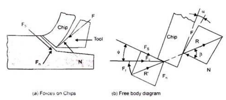
Fig 26
2. 10. 3 Drilling process
Drilling is the operation of making a circular hole by removing some volume of metal from the job by a rotating cutting tool called drill as shown in Figure. Drilling removes solid metal from the job to produce a circular hole. Before drilling, the hole is located by drawing two lines at a right angle (90 deg), and a center punch is used to make an indentation for the drill point at the center to aid the drill in getting started. A suitable drill is held in the drill machine, and the drill machine is then adjusted to operate at the correct cutting speed. The drill machine is started, and the drill starts rotating. Cutting fluid is made to flow, and the cutting process is started. The rotating drill is made to feed into the job. The hole, depending upon its length, may or may not be drilled in one or more steps. After the drilling operation is complete, the drill is removed from the hole, and the power is turned off.
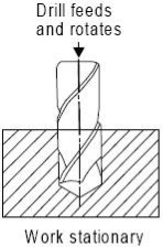
Fig 27.: Drilling operation
2. 10. 4 Milling process
Milling is a process of producing flat, and complex shapes with the use of a multi-point (or multi-tooth) cutting tool. The axis of rotation of the cutting tool is perpendicular to the direction of feed, either parallel or perpendicular to the machined surface. Milling is usually an interrupted cutting operation
Since the teeth of the milling cutter enter, and exit the workpiece during each revolution.
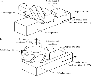
Fig 28
The 15 different types of milling machine operations are:
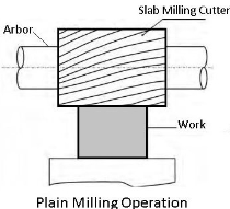
Fig 29
. 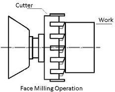
Fig 30
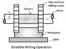
Fig 31
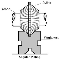
Fig 32
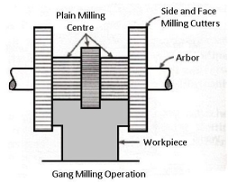
Fig 33
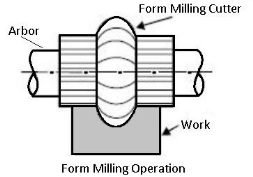
Fig 34
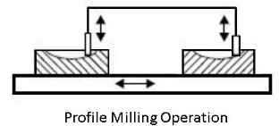
Fig 35
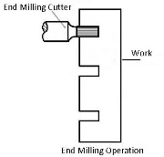
Fig 36
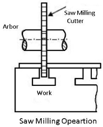
Fig 37
Milling Keyways, Grooves, and Slots
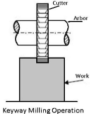
Fig 38
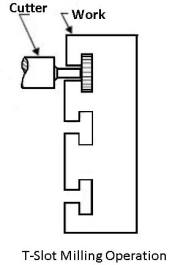
Fig 39
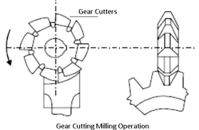
Fig 40
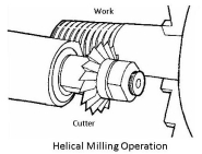
Fig 41
2. 10. 5 Finishing process
Finishing processes aim to alter the surface of a manufactured part to achieve a particular characteristic. Commonly desired characteristics include improved aesthetics, adhesion, solderability, chemical-, corrosion-, tarnish- or wear-resistance, hardness, electrical conductivity, flaw removal, and surface friction control. In limited cases, these techniques may be applied to restore original dimensions or to salvage or repair a part.
There are two main categories of finishing processes, and they largely depend on how they affect a workpiece. These processes are either removing/reshaping finishing or adding/altering finishing. The removing/reshaping processes serve mainly to alter the surface of a part to attain the desired finish by removing or reshaping it. For example, some users desire a more polished, reshaped, smoothed, or abrasive surface, or an aesthetically enhanced exterior. A broad variety of processes are used, but among the most common are abrasive, and sandblasting laser ablation, and engraving, polishing, and superfinishing.
Similarly, the adding/altering processes serve to alter the surface of a part, but rather than removing or reshaping it, a coat of the desired material is added to attain the desired properties that are otherwise missing. There are numerous possible processes to add/alter a part’s surface, but among the most common are anodizing, dyeing, electroplating, electroless plating, plating, powder coating, and spraying.
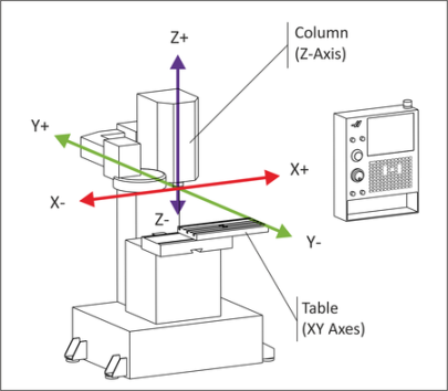
Fig 42
Basics of CNC Programming
There are two ways to program modern CNC machine tools.
The following cycles are typical of the machining operations available when programming a 3-axis CNC milling machine.
Position. Used to move the XYZ coordinates at rapid federate.
Drill one. Used to position the tool at a specific XYZ coordinate position to automatically drill a hole. The automatic drill cycles allow for simple drilling, peck drilling, spot-facing, and bore cycles.
Drill pattern. Used to define polar or rectangular hole arrays for automatic drilling. Line. Used to cut straight lines along an axis or a diagonal at the desired feed rate.
Arc. Used to cut a circle or partial circle that is part of a series of cuts that usually includes lines as well.
Face. Used to define a rectangular zig-zag pattern used to clean off a part surface.
Pocket. Used to clear the material out of a rectangle, circle, or polygon.
Frame. Used to cut the inside or outside outline of a rectangle, circle, or polygon.
Tool. Used to enter tool parameters, machine function parameters, and program pause/stop codes.
Scale/mirror. Used to scale, and/or mirror other part features.
Rotate. Used to repeat other part features around a specific center of rotation.
Example.

Fig 43
2. CAM Programming. This is the more powerful of the two methods. Using this method, you import your part model into a CAM (computer-aided manufacturing) program and define the parameters associated with each, and every machined feature on the part. These parameters include tool diameter, and length, depth of cut, tool path geometry, etc.
Once the part has been designed using conventional mechanical design methods (structural analysis, FEA, fatigue study, etc. ), the part is manufactured using the following method.
1. Create a solid 3D model of the part to be produced. Any standard CAD format is acceptable.
2. Import the solid model into the CAM (computer-aided manufacturing) software. (this demonstration uses MasterCAM)
3. Input the raw material stock size, and set the part’s coordinate origin.
4. Input the necessary information for each tool used in machining the part features. Typically, a tool library will exist, which is simply a database of tools, and their related parameters.
5. For each part feature, select the appropriate tool from the library and set the parameters necessary for machining that feature. Typical parameters include spindle speed, depth of cut, feed rate, number of passes, tool path pattern, etc.
6. Verify the programmed tool path(s) by running the CAM software’s virtual machining cycle.

Additive manufacturing processes work by adding layers of material one at a time to build a solid part from bottom to top. Starting materials include (1) liquid monomers that are cured layer by layer into solid polymers, (2) powders that are aggregated, and bonded layer by layer, and (3) solid sheets that are laminated to create the solid part. The methods of building, and adding the layers to create the solid part include using lasers to solidify the starting material, depositing a soft plastic filament in the outline of each layer, and bonding solid layers together. There is a correlation between the starting material, and the part building techniques. The common approach to preparing the control instructions (part program) in all of the current material addition techniques involves the following steps:
Geometric modeling: This consists of modeling the component on a CAD system to define its enclosed volume. Solid modeling is the preferred technique because it provides a complete, and unambiguous mathematical representation of the geometry.
Tessellation of the geometric model: In this step, the CAD model is converted into a format that approximates its surfaces by triangles or polygons, with their vertices arranged to distinguish the object’s interior from its exterior. The common tessellation format used is STL.
Slicing of the model into layers: In this step, the model in STL file format is sliced into closely spaced parallel horizontal layers. These layers are subsequently used to construct the physical model. By convention, the layers are formed in the x-y plane orientation, and the layering procedure occurs in the z-axis direction. For each layer, a curing path is generated, called the STI file, which is the path that will be followed to cure (or otherwise solidify) the layer.
Stereolithography: It is an additive manufacturing process in which the starting materials are liquid monomers. Polymerization occurs upon exposure to ultraviolet light produced by helium-cadmium or argon-ion lasers. Scan speeds of STL lasers typically range between 500, and 2500 mm/s. The stereolithography apparatus consists of (1) a platform that can be moved vertically inside a vessel containing the photosensitive polymer, and (2) a laser whose beam can be controlled in the x-y direction.
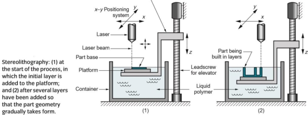
Fig 45
At the start of the process, the platform is positioned vertically near the surface of the liquid photopolymer, and a laser beam is directed through a curing path that comprises an area corresponding to the base (bottom layer) of the part. This and subsequent curing paths are defined by the STI file. The action of the laser is to harden (cure) the photosensitive polymer where the beam strikes the liquid, forming a solid layer of plastic that adheres to the platform. When the initial layer is completed, the platform is lowered by a distance equal to the layer thickness, and a second layer is formed on top of the first by the laser, and so on. Before each new layer is cured, a wiper blade is passed over the viscous liquid resin to ensure that its level is the same throughout the surface. Each layer consists of its area shape, so that the succession of layers, one on top of the previous, creates the solid part shape. Each layer is 0. 076 to 0. 50 mm thick. Thinner layers provide better resolution and allow more intricate part shapes, but processing time is greater. The time required to build the part by this layering process ranges from1 one hour for small parts of simple geometry up to several dozen hours for complex parts. Other factors that affect cycle time are scan speed, and layer thickness.
2. 13. 1 Rapid prototyping
Rapid prototyping is the fast fabrication of a physical part, model, or assembly using 3D computer-aided design (CAD). The creation of the part, model, or assembly is usually completed using additive manufacturing, or more commonly known as 3D printing.
Where the design closely matches the proposed finished product it is said to be a high fidelity prototype, as opposed to a low fidelity prototype, where there is a marked difference between the prototype and the final product.
How Does Rapid Prototyping Work
Rapid prototyping (RP) includes a variety of manufacturing technologies, although most utilize layered additive manufacturing. However, other technologies used for RP include high-speed machining, casting, moulding, and extruding.
While additive manufacturing is the most common rapid prototyping process, other more conventional processes can also be used to create prototypes.
These processes include:
What are the Different Types of Rapid Prototyping
Stereolithography (SLA) or Vat Photopolymerization
This fast and affordable technique was the first successful method of commercial 3D printing. It uses a bath of photosensitive liquid which is solidified layer-by-layer using a computer-controlled ultraviolet (UV) light.
Selective Laser Sintering (SLS)
Used for both metal, and plastic prototyping, SLS uses a powder bed to build a prototype one layer at a time using a laser to heat, and sinter the powdered material. However, the strength of the parts is not as good as with SLA, while the surface of the finished product is usually rough, and may require secondary work to finish it.
Fused Deposition Modelling (FDM) or Material Jetting
This inexpensive, easy-to-use process can be found in most non-industrial desktop 3D printers. It uses a spool of thermoplastic filament which is melted inside a printing nozzle barrel before the resulting liquid plastic is laid down layer-by-layer according to a computer deposition program. While the early results generally had poor resolution and were weak, this process is improving rapidly, and is fast, and cheap, making it ideal for product development.
Selective Laser Melting (SLM) or Powder Bed Fusion
Often known as powder bed fusion, this process is favoured for making high-strength, complex parts. Selective Laser Melting is frequently used by the aerospace, automotive, defense, and medical industries. This powder bed-based fusion process uses a fine metal powder which is melted in a layer by layer manner to build either prototype or production parts using a high-powered laser or electron beam. Common SLM materials used in RP include titanium, aluminum, stainless steel, and cobalt chrome alloys.
Laminated Object Manufacturing (LOM) or Sheet Lamination
This inexpensive process is less sophisticated than SLM or SLS, but it does not require specially controlled conditions. LOM builds up a series of thin laminates that have been accurately cut with laser beams or another cutting device to create the CAD pattern design. Each layer is delivered and bonded on top of the previous one until the part is complete.
Digital Light Processing (DLP)
Similar to SLA, this technique also uses the polymerization of resins which are cured using a more conventional light source than with SLA. While faster, and cheaper than SLA, DLP often requires the use of support structures and post-build curing.
An alternative version of this is Continuous Liquid Interface Production (CLIP), whereby the part is continuously pulled from a vat, without the use of layers. As the part is pulled from the vat it crosses a light barrier that alters its configuration to create the desired cross-sectional pattern on the plastic.
This technique allows for one or many parts to be printed at one time, although the parts produced are not as strong as those created using SLS. Binder Jetting uses a powder bed onto which nozzles spray micro-fine droplets of a liquid to bond the powder particles together to form a layer of the part.
Each layer may then compacted by a roller before the next layer of powder is laid down, and the process begins again. When complete the part may be cured in an oven to burn off the binding agent and fuse the powder into a coherent part.
Product designers use this process for the rapid manufacturing of representative prototype parts. This can aid the visualization, design, and development of the manufacturing process ahead of mass production.
Originally, rapid prototyping was used to create parts, and scale models for the automotive industry although it has since been taken up by a wide range of applications, across multiple industries such as medical, and aerospace.
Rapid tooling is another application of RP, whereby a part, such as an injection mould plug or ultrasound sensor wedge, is made and used as a tool in another process.
Advantages
There are several rapid prototyping advantages, such as being able to gain a more complete picture of how a product will look or perform in the early stage of the design, and manufacturing cycle, allowing changes or improvements to be implemented earlier in the process. The time this takes can vary from a few days to several months, depending on the methods used.
RP is a very cost-effective way to prototype products as it is an automated process, requiring less staff to operate. This process is also extremely precise, being able to use computer-aided design (CAD) to help reduce the amount of material wastage, and does not require special tools for prototyping each new product. Being able to act quickly, and solve any problems also reduces the risk of costly errors during the manufacturing stage.
Rapid Prototyping helps designers present new concepts to board members, clients, or investors so that they can understand, and approve development or product. These visualizations can also allow designers to gain ready feedback from customers, and clients based on an actual physical product rather than a concept.
As rapid prototyping is an iterative process it allows customer requirements to be incorporated into designs cost-effectively. The process cuts out the need for customized products to be designed from scratch while providing greater choice, and flexibility for customers.
3. 13. 2 Rapid tooling
Rapid tooling is known by many names including prototype tooling, and soft tooling, but it is essentially pared-back injection mold tooling enabling you to quickly, and cheaply get parts. It is important to differentiate between the concept and the realization as there are many ways of achieving the same results.
Conceptually it is any type of injection mold tooling, manufactured quickly, and inexpensively to enable testing, and validation of parts before you invest in production tooling. In terms of realization, anything that allows you to do this can apply.
The main reason people manufacture rapid tooling is for testing, and validation of parts in the prototyping stages of new product development. Although other prototyping options such as 3D printing, CNC, or vacuum casting would generally allow faster, and cheaper prototypes the main advantage of rapid tooling lies in the process, and materials.
HLH Rapid Tooling (Proto Tool)
Rapid tooling allows you to use the actual production grades of material, allowing you a much clearer picture of how the parts will act in real-world applications, and enabling you to test, and confirm you have made the correct material choices. Parts are also injection moulded as they would be in production so you can also use them for stress, and impact testing, for example, exploring any weak areas due to weld lines or other imperfections from the injection moulding process such as shrink and warping. With this information, you can then better determine if any changes need to be made before expensive production tooling.
People also use rapid tooling to test the parameters of production and ensure they will get parts that fill correctly and act as desired. In this way, engineers, and designers can catch a lot of future process flaws, and implement redesigns or other measures to prevent issues with the final parts.
There are several other reasons for selecting rapid tooling, other than the prototyping, and testing already mentioned. Principally it is a low cost, rapid option for manufacturing injection molded parts. The advantages of speed allow you to get parts to market quickly, and the cost advantages allow both market testing and mean it is a suitable choice for lower volume production runs.
In terms of how to make a rapid tool, many different approaches are depending on the part and requirements but the general idea is to reduce as far as possible the time is taken, and the costs involved in the manufacture. This includes various techniques such as;
An emerging option is also to use 3D printing in both plastics, and metals to replace a lot of the conventional parts of the tools.
Start Today With HLH
Different companies approach the manufacture of rapid tools in different ways but the very nature of rapid tooling, and product development process means most specialist companies can offer a level of flexibility to achieve what you need.
These are widely used in fabrication, and assembly work. In this process, two or more pieces of metal parts are joined together to produce the desired shape, and size of the product. The joining processes are carried out by fusing, pressing, rubbing, riveting, screwing, or any other means of assembling. These processes are used for assembling metal parts and in general fabrication work. Such requirements usually occur when several pieces are to be joined together to fabricate a desired structure of products. These processes are used in developing steam or water-tight joints. A temporary, semi-permanent or permanent type of fastening to make a good joint is generally created by these processes. The temporary joining of components can be achieved by the use of nuts, screws, and bolts. Adhesives are also used to make temporary joints. Some of the important, and common joining processes are:
(1) Welding (plastic or fusion), (2) Brazing, (3) Soldering, (4) Riveting, (5) Screwing, (6) Press fitting, (7) Sintering, (8) Adhesive bonding, (9) Shrink fitting, (10) Explosive welding, (11) Diffusion welding, (12) Keys, and cotters joints, (13) Coupling, and (14) Nut, and bolt joints.
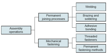
Assembly is the basic type of manufacturing operation in which two or more separate parts are joined to form a new entity. Components of the new entity are connected either permanently or semi-permanently. Permanent joining processes include welding, brazing, soldering, and adhesive bonding. They form a joint between components that cannot be easily disconnected.
Certain mechanical assembly methods are available to fasten two (or more) parts together in a joint that can be conveniently disassembled. They are called temporary joining processes. The use of screws, bolts, and other threaded fasteners are important traditional methods in this category.
Other mechanical assembly techniques, called semi-permanent processes, form a more permanent connection than temporary processes. These include rivets, press fitting, and expansion fits.
Special joining and fastening methods are used in the assembly of electronic products. Some of the methods are identical to or are adaptations of the preceding processes, for example, soldering. Electronics assembly is concerned primarily with the assembly of components such as integrated circuit packages to printed circuit boards to produce the complex circuits.
2. 15. 1 Physics of welding
Welding is a fabrication process whereby two or more parts are fused by means of heat, pressure, or both forming a join as the parts cool. Welding is usually used on metals, and thermoplastics but can also be used on wood. The completed welded joint may be referred to as a weldment.
Some materials require the use of specific processes, and techniques. A number is considered 'unweldable,' a term not usually found in dictionaries but useful, and descriptive in engineering.
The parts that are joined are known as the parent material. The material added to help form the join is called filler or consumable. The form of these materials may see them referred to as parent plate or pipe, filler wire, consumable electrode (for arc welding), etc.
Consumables are usually chosen to be similar in composition to the parent material, thus forming a homogenous weld, but there are occasions, such as when welding brittle cast irons, when filler with a very different composition, and, therefore, properties are used. These welds are called heterogeneous.
The completed welded joint may be referred to as a well-meant.
How Does Welding Work?
As opposed to brazing, and soldering, which do not melt the base metal, welding is a high heat process that melts the base material. Typically with the addition of filler material.
Heat at a high temperature causes a weld pool of molten material which cools to form the join, which can be stronger than the parent metal. Pressure can also be used to produce a weld, either alongside the heat or by itself.
It can also use a shielding gas to protect the melt, and filler metals from becoming contaminated or oxidized.
Plastics welding also uses heat to join the materials (although not in the case of solvent welding) and is achieved in three stages.
Firstly, the surfaces are prepared before the heat, and pressure is applied, and, finally, the materials are allowed to cool to create fusion. Joining methods for plastics can be separated into external or internal heating methods, depending on the exact process used.
Wood welding uses heat generated from friction to join the materials. The materials to be joined are subjected to a great deal of pressure before a linear friction movement creates heat to bond the workpiece together.
This is a fast process that allows the wood to be joined without adhesives or nails in a matter of seconds.

Fig 46
A connection between the ends or edges of two parts making an angle to one another of 135-180° inclusive in the region of the joint.
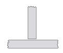
A connection between the end or edge of one part, and the face of the other part, the parts making an angle to one another of more than 5 up to, and including 90° in the region of the joint.

Fig 47
A connection between the ends or edges of two parts making an angle to one another of more than 30 but less than 135° in the region of the joint.

Fig 48
A connection between the edges of two parts making an angle to one another of 0 to 30° inclusive in the region of the joint.
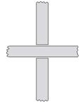
Fig 49
A connection in which two flat plates or two bars are welded to another flat plate at right angles, and on the same axis.

Fig 50
A connection between two overlapping parts making an angle to one another of 0-5° inclusive in the region of the weld or welds.
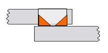
The joint between two overlapping components made by depositing a fillet weld around the periphery of a hole in one component to join it to the surface of the other component exposed through the hole.
Plug weld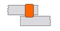
Fig 52
Weld is made by filling a hole in one component of a workpiece with filler metal to join it to the surface of an overlapping component exposed through the hole (the hole can be circular or oval).
Full penetration weld
Fig 53
The welded joint where the weld metal fully penetrates the joint with complete root fusion. In the US the preferred term is complete joint penetration weld (CJP, see AWS D1. 1).
Partial penetration weld
Fig 54
Weld in which the fusion penetration is intentionally less than full penetration. In the US the preferred term is partial joint penetration weld (PJP).
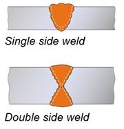
Fig 55
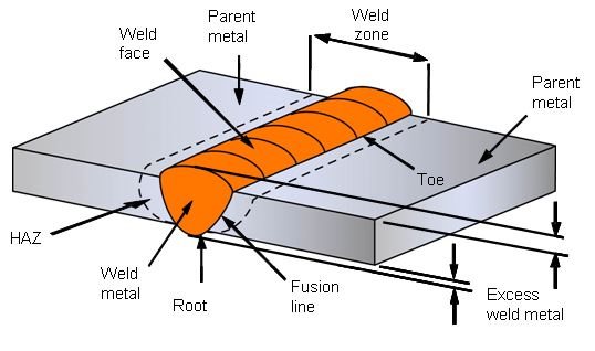
Buttweld
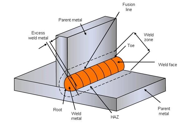
Fig 56 Fillet weld
Parent MetalMetal to be joined or surfaced by welding, braze welding, or brazing.
Filler MetalMetal added during welding, braze welding, brazing, or surfacing.
Weld MetalAll metal melted during the making of a weld and was retained in the weld.
Heat Affected Zone (HAZ)The part of the parent metal metallurgical is affected by the weld or thermal cutting heat, but not melted.
Fusion LineThe boundary between the weld metal, and the HAZ in a fusion weld. This is a non-standard term for weld junction.
Weld ZoneA zone containing the weld metal, and the HAZ.
Weld FaceThe surface of a fusion weld is exposed on the side from which the weld has been made.
Weld RootZone on the side of the first run furthest from the welder.
Weld ToeThe boundary between a weld face, and the parent metal or between runs. This is a very important feature of a weld since toes are points of high-stress concentration, and often they are initiation points for different types of cracks (eg fatigue cracks, cold cracks).
To reduce the stress concentration, toes must blend smoothly into the parent metal surface.
Excess Weld MetalWeld metal lying outside the plane joining the toes. Other non-standard terms for this feature: reinforcement, overfill.
Note: the term reinforcement, although commonly used, is inappropriate because any excess weld metal over, and above the surface of the parent metal does not make the joint stronger.
The thickness considered when designing a welded component is the design throat thickness, which does not include the excess weld metal.
Run (pass)
Fig 57
The metal melted or deposited during one passage of an electrode, torch, or blowpipe.
LayerThe stratum of weld metal consisting of one or more runs.
Different processes are determined by the energy source used, with a variety of different techniques available.
Until the end of the 19th century, forge welding was the only method used, but later processes, such as arc welding, have since been developed. Modern methods use a gas flame, electric arc, lasers, electron beam, friction, and even ultrasound to join materials.
Care needs to be taken with these processes as they can lead to burns, electric shock, damaged vision, exposure to radiation, or inhaling of poisonous welding fumes, and gases.
What are the Different Welding Types, and What are They Used for?
There are a variety of different processes with their techniques, and industrial applications, these include:
This category includes several common manual, semi-automatic, and automatic processes. These include metal inert gas (MIG) welding, stick welding, tungsten inert gas (TIG) welding also known as gas tungsten arc welding (GTAW), gas welding, metal active gas (MAG) welding, flux-cored arc welding (FCAW), gas metal arc welding (GMAW), submerged arc welding (SAW), shielded metal arc welding (SMAW), and plasma arc welding.
These techniques usually use filler material and are primarily used for joining metals including stainless steel, aluminium, nickel, and copper alloys, cobalt, and titanium. Arc welding processes are widely used across industries such as oil, and gas, power, aerospace, automotive, and more.
Friction welding techniques join materials using mechanical friction. This can be performed in a variety of ways on different welding materials including steel, aluminum, or even wood.
The mechanical friction generates heat which softens the materials which mix to create a bond as they cool. How the joining occurs is dependent on the exact process used, for example, friction stir welding (FSW), friction stir spot welding (FSSW), linear friction welding (LFW), and rotary friction welding (RFW).
Friction welding doesn't require the use of filler metals, flux, or shielding gas.
Friction is frequently used in aerospace applications as it is ideal for joining otherwise 'non-weldable' light-weight aluminum alloys.
Friction processes are used across the industry and are also being explored as a method to bond wood without the use of adhesives or nails.
This fusion joining process uses a beam of high-velocity electrons to join materials. The kinetic energy of the electrons transforms into heat upon impact with the workpieces causing the materials to melt together.
Electron beam welding (EBW) is performed in a vacuum (with the use of a vacuum chamber) to prevent the beam from dissipating.
There are many common applications for EBW, as can be used to join thick sections. This means it can be applied across several industries from aerospace to nuclear power, and automotive to rail.
Used to join thermoplastics or pieces of metal, this process uses a laser to provide a concentrated heat ideal for barrow, deep welds, and high joining rates. Being easily automated, the high welding speed at which this process can be performed makes it perfect for high volume applications, such as within the automotive industry.
Laser beam welding can be performed in the air rather than in a vacuum such as with electron beam joining.
This is a fast process that is commonly used in the automotive industry. This process can be split into two types, resistance spot welding, and resistance seam welding.
Spot welding uses heat delivered between two electrodes which are applied to a small area as the workpiece is clamped together.
Seam welding is similar to spot welding except it replaces the electrodes with rotating wheels to deliver a continuous leak-free weld.
2. 15. 2 Physics of brazing
Brazing is a joining process traditionally applied to metals (but also to ceramics) in which molten filler metal (the braze alloy) flows into the joint.
The melting point of the filler metal is above 450°C, but always below the melting temperature of the parts to be joined, which distinguishes the process from welding where high temperatures are used to melt the base metals together.
The filler metal, while heated slightly above the melting point, is protected by a suitable atmosphere which is often a flux. The molten filler metal cools to join the workpieces together providing a strong join between similar or dissimilar metals.
The atmospheres in which the brazing process can be undertaken include air, combusted fuel gas, ammonia, nitrogen, hydrogen, noble gases, inorganic vapours, and vacuum, using a variety of heating sources such as a torch, furnace, and induction coil.
To achieve a sound brazed joint, the filler and parent materials should be metallurgical compatible, and the joint design should incorporate a gap into which the molten braze filler can be drawn or distributed by capillary action. The required joint gap is dependent on many factors, including the brazing atmosphere, and the composition of the base material, and braze alloy.
Ideal for joining dissimilar metals, brazing is a commercially accepted process used in a wide range of industries due to its flexibility, and the high integrity to which joints may be produced. This makes it reliable in critical, and non-critical applications, and it is one of the most widely used joining methods.
2. 15. 3 Physics of soldering
Soldering is a joining process used to join different types of metals together by melting solder. Solder is a metal alloy usually made of tin and leads which is melted using a hot iron. The iron is heated to temperatures above 600 degrees Fahrenheit which then cools to create a strong electrical bond.
How does it Work?
Solder is melted by using heat from an iron connected to a temperature controller. It is heated up to temperatures beyond its melting point at around 600 degrees Fahrenheit which then causes it to melt, which then cools creating the soldered joint.
As well as creating strong electrical joints solder can also be removed using a desoldering tool.
Solder is a metal alloy used to create strong permanent bonds; such as copper joining in circuit boards, and copper pipe joints. It can also be supplied in two different types, and diameters lead, and lead-free, and also can be between. 032”, and. 062”. Inside the solder, the core is the flux, a material used to strengthen and improve its mechanical properties.
What Metals are used?
Filler metals used in soldering were once lead-based (lead solder), however, owing to regulations, lead-based solders are increasingly replaced with lead-free solders, which may consist of antimony, bismuth, brass, copper, indium, tin, or silver.
Which Flux Can be Used for Soldering?
Occasionally at the site of the joint, there are impurities such as oil, dirt, or oxidation, the flux helps prevent oxidation, and can sometimes chemically clean the metal. The flux used is rosin flux which helps the mechanical strength, and electrical contact of electrical joints. Sometimes it is also possible to apply a ‘wetting agent’ to reduce the surface tension.
Types of Soldering
There are three types of soldering which use increasingly higher temperatures, which in turn produce progressively stronger joints:
Soft soldering (90 °C - 450 °C) - This process has the lowest filler metal melting point of all the soldering types at less than around 400°C these filler metals are usually alloys, often containing lead with liquidus temperatures under 350°C. Because of the low temperatures used in soft soldering, it thermally stresses components the least but does not make strong joints, and is then therefore unsuitable for mechanical load-bearing applications. It is also not suited for high-temperature use as this type of solder loses strength and melts.
Hard (silver) soldering (>450 °C) – Brass or silver is the bonding metal used in this process, and requires a blowtorch to achieve the temperatures at which the solder metals.
Brazing (>450 °C) – This type of soldering uses metal with a much higher melting point than those used in hard, and soft soldering. However, similarly to hard soldering, the metal being bonded is heated as opposed to being melted. Once both the materials are heated sufficiently, you can then place the soldering metal between them which melts and acts as a bonding agent.
Uses of a Soldering Iron
A soldering iron is a hand tool used to heat solder, usually from an electrical supply at high temperatures above the melting point of the metal alloy. This allows for the solder to flow between the workpieces needing to be joined.
This soldering tool is made up of an insulated handle, and a heated pointed metal iron tip. Good soldering is influenced by how clean the tip of your soldering iron is. To maintain cleanliness, a user will hold the soldering iron and use a wet sponge to clean the soldering iron tip before soldering components or making soldered connections.
In addition to the soldering iron, solder suckers are an important part of the soldering setup. If excessive solder is applied, these small tools are used to remove the solder, leaving only that desired.
What is a Soldering Gun Used For?
Soldering guns are used for applications where more heat is required as irons use lower power. This tool is used for joining stained glass, light sheet metal, and heavy electronic soldering work. When you need to solder intermittently, the soldering gun is much more practical as it cools much quicker.
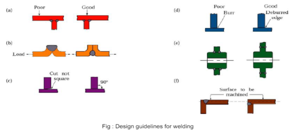
Fig 58
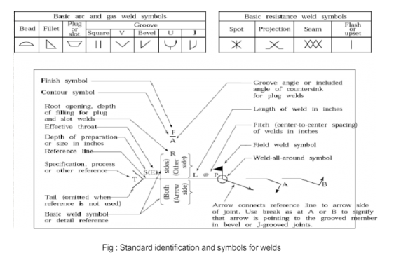
Fig 59
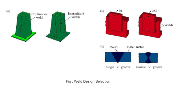
Fig 60
What is solid-state welding?
In all those welding processes where melting of faying surfaces of parent materials don’t take place are called solid-state welding. Unlike fusion welding, here application of heat is not necessary. However, the application of pressure is required for getting a sound joint, and thus it is also termed Pressure welding. It is worth nothing that sometimes base materials are heated to an elevated temperature while joining by solid-state welding process; however, temperature always remains below the melting point.
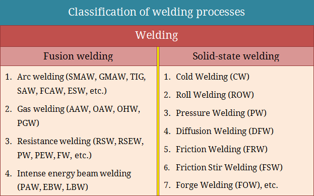
Examples of solid-state welding
Any welding process where no melting takes place comes under this group. Although fusion welding processes are many, there exist quite a few solid-state welding processes also. Some examples are provided below. Note that many people consider the resistance welding group as solid-state welding; here the same is kept under fusion welding as nugget is formed due to melting of faying surfaces by resistance heating.
Advantages of solid-state welding processes
Disadvantages of solid-state welding processes
Similarities between fusion welding, and solid-state welding
Differences between fusion welding, and solid-state welding
Fusion Welding | Solid-State Welding |
Faying surfaces of the base metals are fused to form coalescence during welding. Filler metal, if used, is also fused. | No such melting takes place in solid-state welding. However, the base metals may be heated to an elevated temperature without melting. |
Application of heat during welding is necessary. Heat can be applied by various means such as electric arc, fuel-gas flame, resistance heating, laser beam, etc. | No such heat source is usually required, but the pressure may be applied externally for welding. |
The filler material can be applied easily. | Usually, no filler is applied. |
Because of excessive heating, a noticeable heat-affected zone (HAZ) exists surrounding the weld bead. | HAZ is usually not noticeable. A narrow HAZ may exist in certain cases. |
Mechanical and metallurgical properties of the parent materials are severely affected during fusion welding because of intense heating. | Mechanical properties usually remain unaltered in solid-state welding. Sometimes minor changes may occur. |
Dissimilar metal joining by fusion welding is a challenging task, especially if the duo has substantially different melting points and coefficients of thermal expansion. | Joining dissimilar metals is comparatively easier by solid-state welding processes like melting, and solidification is not involved here. |
The level of distortion is very high in fusion welding owing to excessive heat input per unit area. | Solid-state welding produces minimal distortion. |
Joint design and edge preparation are not crucial. These parameters mainly influence achievable penetration. | Joint design, edge preparation, and surface preparation are crucial here as the processes require specific mating surfaces. |
Examples of fusion welding processes:
| Examples of solid-state welding processes:
|
The adhesive bonding process is most commonly used in the aircraft and automobile industries where sheet metals are joined in various configurations. In it, unlike in brazing, and soldering, there is no uncertainty about the flow of the adhesive in the joint. This is so because the adhesive is first applied on the surfaces, and the joint is made with subsequent application of heat, and pressure. However, this advantage should not be overemphasized because of the inherent low strength of the resulting joint.
Two types of bonding forces take part in an adhesive joint. Of these, one is the van der Waals forces due to the constant movement of the positive, and the negative charges of molecules. The other is the polar force, between the adhesive, and the relatively brittle oxide film, due to the dipole adhesive molecules. This force is normally several orders of magnitude higher than the van der Waals force.
The coefficient of thermal expansion and the elastic properties of the adhesive normally differ very widely from those of the metals to be joined. Therefore, the mechanical properties of an adhesive joint need a careful examination.
The factors that affect the strength, and the other mechanical properties of such a joint are:
(i) nature, and dimensions of the joint. The strength of a lap joint increases with the overlapped area and reduces with the joint thickness.
(ii) The contact angle at the solid-liquid interface. In the joint, there is always a possibility of an air bubble getting trapped in the metal cavity. The radius R of the bubble is determined by the size, and shape of the cavity together with the contact angle ɸ (Fig. 5. 23). It can be shown that the tensile stress necessary to propagate a crack from the cavity is given by –
Where Ea, va, and γa are Young’s modulus, Poisson’s ratio, and the surface energy, respectively, of the adhesive.
Moreover, the stress concentration factor due to the formation of a meniscus, shown in Fig. 5. 24, depends on the contact angle. The maximum stress concentration factor increases continuously from about 1 to 2. 3 as ɸ increases from 0 to 90°.
Fig 61
Up to a value ɸ < 30°, the maximum stress concentration factor, and the failure both occur in the body of the adhesive. Beyond ɸ = 30°, the maximum stress concentration factor, and consequently the failure, shift to the interface. The latter situation normally results in lower strength. In actual practice, the adhesive is extruded (by means of external pressure) from the joint to prevent the formation of any meniscus.
(iii) The residual stress, and the stress concentration. The adhesive in the joint shrinks due to both cooling, and polymerization. This shrinkage results in residual tensile stress in the adhesive, and consequently reduces the strength of the joint.
If a lap joint of two metal sheets of equal thickness t (see Fig. 5. 25) is considered, it can be shown that the stress concentration factor in shear due to dissimilar materials is given by –
where Ga is the shear modulus of the adhesive, and E is Young’s modulus of the metal. Other factors, e. g., shape, and bending of the adhesive, also give rise to stress concentration.
References:
1. Kalpakjian and Schmid, Manufacturing processes for engineering materials (5th Edition)- Pearson India, 2014.
2. Mikell P. Groover, Fundamentals of Modern Manufacturing: Materials, Processes, and Systems.
3. Manufacturing Technology by P.N. Rao., MCGRAW HILL INDIA.
4. Materials and Manufacturing by Paul Degarmo.
5. Manufacturing Processes by Kaushish, PHI.
6. Principles of Foundry Technology, Jain, MCGRAW HILL INDIA
7. Production Technology by RK Jain.
8. Degarmo, Black &Kohser, Materials and Processes in Manufacturing.
