The grinding wheel consists of hard abrasive grains called grits, which perform the cutting or material removal, held in the weak bonding matrix. A grinding wheel is commonly identified by the type of abrasive material used. The conventional wheels include aluminum oxide and silicon carbide wheels while diamond and CBN (cubic boron nitride) wheels fall in the category of a super abrasive wheel.
Marking system for conventional grinding wheel
The standard marking system for a conventional abrasive wheel can be as follows:
51 A 60 K 5 V 05,
Selection of grinding wheels
Selection of grinding wheel means selection of the composition of the grinding wheel and this depends upon the following factors:
Key points:
1) The grinding wheel consists of hard abrasive grains called grits.
2) Standard marking system of the conventional grinding wheel.

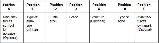
3.2.1 Abrasive
Abrasive processes consist of a variety of operations in which the tool is made of an abrasive material, the most common examples of which are grinding (using wheels, known as bonded abrasives), honing, and lapping. An abrasive is a small, non-metallic hard particle having sharp cutting edges and an irregular shape. Abrasive processes, which can be performed on a wide variety of metallic and non-metallic materials, remove material in the form of tiny chips and produce surface finishes and dimensional accuracies that are generally not obtainable through other machining or manufacturing processes.
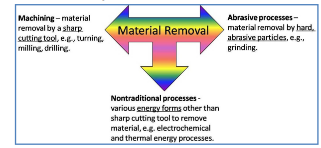
Fig 1
Types of abrasives
(a). Aluminum oxide
(b). Silicon carbide
(c). Diamond
(d). cBN (cubic boron nitride)
Grit size
The grain size affects the material removal rate and the surface quality of the workpiece in grinding.
Grade
The worn-out grit must pull out from the bond and make room for fresh sharp grit in order to avoid the excessive rise of grinding force and temperature. Therefore, a soft grade should be chosen for grinding hard material. On the other hand, during the grinding of low strength soft material grit does not wear out so quickly. Therefore, the grit can be held with a strong bond so that premature grit dislodgement can be avoided.
Structure / concentration
The structure should be open for grinding wheels engaged in high material removal to provide chip accommodation space. The space between the grits also serves as a pocket for holding grinding fluid. On the other hand, densely structured wheels are used for longer wheel life, for holding precision forms and profiles.
3.2.2 Bonds
Vitrified bond
Vitrified bond is suitable for high stock removal even in dry conditions. It can also be safely used in wet grinding. It cannot be used where mechanical impact or thermal variations are like to occur. This bond is also not recommended for very high-speed grinding because of possible breakage of the bond under centrifugal force.
Resin bond
Conventional abrasive resin bonded wheels are widely used for heavy-duty grinding because of their ability to withstand shock load. This bond is also known for its vibration absorbing characteristics and finds its use with diamond and cBN in grinding of cemented carbide and steel respectively. Resin bond is not recommended with alkaline grinding fluid for a possible chemical attack leading to bond weakening. Fiberglass reinforced resin bond is used with cut-off wheels which require added strength under high-speed operation.
Shellac bond
At one time this bond was used for flexible cut-off wheels. At present use of shellac, bond is limited to grinding wheels engaged in the fine finish of rolls.
Oxychloride bond
It is a less common type bond, but still can be used in disc grinding operation. It is used under dry conditions.
Rubber bond
Its principal use is in thin wheels for wet cut-off operation. Rubber bond was once popular for finish grinding on bearings and cutting tools.
Metal bond
Metal bond is extensively used with super abrasive wheels. The extremely high toughness of metal bonded wheels makes these very effective in those applications where form accuracy, as well as large stock removal, is desired.
Electroplated bond
This bond allows large (30-40%) crystal exposure above the bond without the need for any truing or dressing. This bond is specially used for making small diameter wheels, form wheels, and thin super abrasive wheels. Presently it is the only bond for making wheels for abrasive milling and ultra-high-speed grinding.
Brazed bond
This is relatively a recent development, allows crystal exposure as high as 60-80%. Besides, grit spacing can be precisely controlled. This bond is particularly suitable for very high material removal either with diamond or cBN wheel. The bond strength is much greater than provided by the electroplated bond. This bond is expected to replace electroplated bond in many applications.
Key points:
1) Vitrified bond is suitable for high stock removal even in dry conditions.
2) Brazed bond is particularly suitable for very high material removal either with diamond or cBN wheel.
3) Diamond grit is best suited for grinding cemented carbides, glass, sapphire, stone, granite, marble, concrete, oxide, non-oxide ceramic, fiber-reinforced plastics, ferrite, graphite
Grinding wheel cutting action is done by different types of particles called abrasive particles like granite, bonding materials, etc. When the wheel rotates this particle used to come in contact with the workpiece and removes the metal from work. some of the important thing in this grinding wheel is, some of the particles used in the grinding wheel have self-sharpening action, this can sharp there cutting particles at the time of the cutting process. an make them self particles sharp.
At some times on the cutting, the material gets brakes or get cracks this is due to the resistance offered by the workpiece. By this, we can get the new cutting points to make further operation.
There are some factors affecting wheel selection:
A grinding wheel requires two types of specification
Geometrical specification
This is decided by the type of grinding machine and the grinding operation to be performed in the workpiece. This specification mainly includes wheel diameter, width and depth of rim, and the bore diameter. The wheel diameter, for example, can be as high as 400mm in high efficiency grinding or as small as less than 1mm in internal grinding. Similarly, the width of the wheel may be less than an mm in dicing and slicing applications. Standard wheel configurations for conventional and super abrasive grinding wheels are shown in Fig.

Fig 2
Compositional specifications
Specification of a grinding wheel ordinarily means compositional specification. Conventional abrasive grinding wheels are specified encompassing the following parameters.
An expression for the wear rate of the grinding wheel is developed from a consideration of the fracture behaviour of brittle materials, whose fracturing probability is believed to show the strong time and stress dependence. It is shown that the wear rate of grinding wheels is to be expressed as the single exponential function of the grinding velocity and as the double exponential function of the grinding force. Experimental results confirm the theoretical interpretation. Fracture-dominated wear of abrasive grains is the most important mechanism of material removal from an abrasive wheel during the grinding process. A fracture occurs as a consequence of tensile stresses induced in the abrasive grains by grinding forces to which they are subjected. Experimental work is extracted from the literature and compared with a model abrasive grain using a variety of abrasive grain materials such as alumina, silicon carbide, cubic boron nitride, and diamond, with loads applied to the apex and the rake face of an abrasive wedge. The relationship between the wear of grinding wheels, component grinding forces, and induced stresses in the model abrasive grains is described in detail. A significant correlation is found between the maximum value of tensile stress induced in the abrasive grain material and the appropriate wheel-wear parameter (grinding ratio). It is concluded that the magnitude of tensile stresses induced in the grain material by grinding forces at the rake face is the best indicator of wheel wear during the grinding process.
The infrared radiation pyrometer with an optical fiber is developed and applied for the temperature measurement in the surface grinding process of carbon steels. Experimental data such as the temperature, the number and the size of effective cutting grains, and the grinding forces are obtained over the wheel life, and they are used for the calculation of the thermal energy fraction to the workpiece, the grinding wheel, and the chips. Thermal damage begins to be caused on the ground surface, as the attrition wear of grains decreases the number of effective cutting grains and degrades the efficiency of the grinding wheel. The measuring of radiation pulses from the cutting grains makes it possible to detect the degradation of the grinding wheel at an early stage of wheel life and prevent severe damages on the work surface.
3.6.1 Dressing
The dressing is the conditioning of the wheel surface which ensures that grit cutting edges are exposed from the bond and thus able to penetrate the workpiece material. Also, in dressing attempts are made to splinter the abrasive grains to make them sharp and free cutting and also to remove any residue left by the material being ground. Dressing, therefore, produces micro-geometry. The structure of the micro- geometry of the grinding wheel determines its cutting ability with a wheel of a given composition. The dressing can substantially influence the condition of the grinding tool.
Truing and dressing are commonly combined into one operation for conventional abrasive grinding wheels but are usually two distinctly separate operations for the super abrasive wheel.
Dressing of super abrasive wheel
Machining Time required for cylindrical grinding (T) = Length of cut x Number of cuts Feed/rev x R.P.M
Length of cut = length of tapper + over travel
3.6.2 Truing
Truing is the act of regenerating the required geometry on the grinding wheel, whether the geometry is a special form or flat profile. Therefore, truing produces the macro-geometry of the grinding wheel.
Truing is also required on a new conventional wheel to ensure concentricity with the specific mounting system. In practice, the effective macro-geometry of a grinding wheel is of vital importance and the accuracy of the finished workpiece is directly related to effective wheel geometry.
Truing tools
There are four major types of truing tools:
(i) Steel cutter:
These are used to roughly true coarse grit conventional abrasive wheel to ensure freeness of cut.
(ii) Vitrified abrasive stick and wheel:
It is used for offhand truing of conventional abrasive wheel. These are used for truing resin bonded super abrasive wheel.
(iii) Steel or carbide crash roll
It is used to crush-true the profile on a vitrified bond grinding wheel. Diamond truing tool:
Single point diamond truing tools
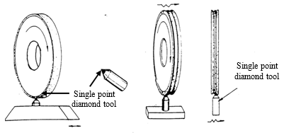
Fig 3 Application of single-point diamond truing tool Multi stone diamond truing tool
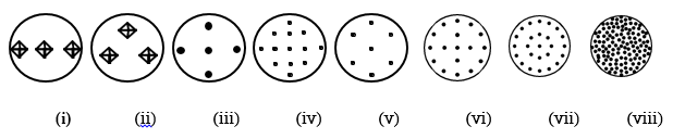
Distribution of diamond | Diamond weight | Distribution of diamond | Diamond weight |
(i) 1 layer-3stone | 10 | (v) 5 layer-17 stone | 50 |
(ii) 2 layer-3 stone | 10 | (vi) 5 layer-7 stone | 10 |
(iii) 3 layer-5 stone | 10 | (vii) 5 layer-25 stone | 250 |
(iv) 5 layer-13 stone | 25 | (viii) throughout | 50 |
Fig 4 Diamond distribution pattern of diamond particles in multi-stone diamond
(iv) Impregnated diamond truing tools
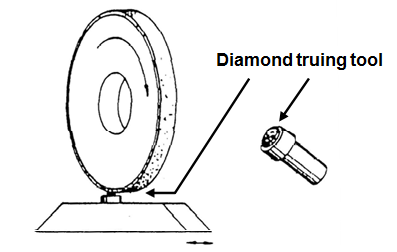
Fig 5. Impregnated diamond truing tools
Rotary powered diamond truing wheels
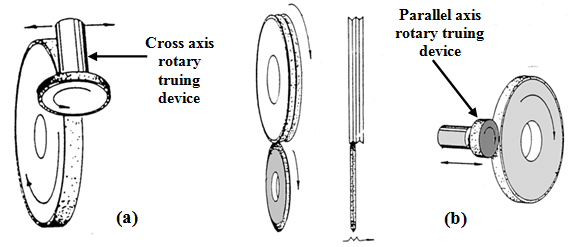
Fig 6. Rotary power truing wheel being used in (a) cross-axis (b) parallel-axis
Surface set truing wheels
Impregnated truing wheels
Electroplated truing tool
Key points
1) Machining Time required for cylindrical grinding (T) = Length of cut x Number of cuts Feed/rev x R.P.M
2) Length of cut = length of tapper + over travel
3) Truing and dressing are commonly combined into one operation for conventional abrasive grinding wheels but are usually two distinctly separate operations for the super abrasive wheel.
4) Truing produces the macro-geometry of the grinding wheel.
The chip thickness in milling depends on the tool rotated angle, as shown in Figure 3.10, where several chip thicknesses for several angles are presented. It is calculated by using
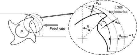
Fig 7
The chip thickness for several rotation angles
Ac =fz·senφ
Where ac is the chip thickness in mm, also known as t o tm whereas fz is the feed per tooth and (φ is the rotated angle by the tool edge into the material, viewing Eq. 3.3 when the angle is 90° and the chip section is the feed per tooth.
3.8.1 Surface grinding
If the particles are present on the face of a grinding wheel and it is used for performing the machining operation then this type of grinding process is called a surface grinding operation.
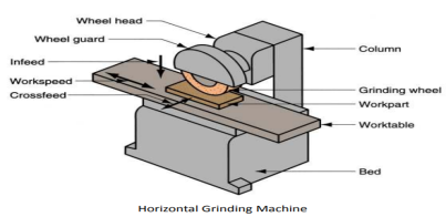
Fig 8
The functioning of various parts of the Surface Grinding machine
1. Base: The base acts as a support for the entire assembly and it also acts as an absorber of vibrations.
2. Hand Traversing Wheel: The hand traversing wheel is used to adjust the worktable in a longitudinal direction i.e. the worktable can be moved in forward and backward direction by the use of the Hand Traversing Wheel.
3.Cross Slide Handwheel: This type of handwheel is used to adjust the worktable in up and down direction so that the workpiece is to be placed in exact dimension according to the Grinding wheel.
4. Work Table: The worktable is the place where the workpiece is to be held properly.
5.Column: It is a vertical column where the wheel guard, wheel head, and abrasive wheel are mounted.
6.Wheel Head: The wheel head is the compartment that has to be moved up and down so that the grinding wheel can touch the workpiece.
7. Vertical Feed Hand Wheel: This hand wheel is used to give feed to the wheel head in a vertical direction which also indicates the depth of cut from the surface of the workpiece.
8. Wheel Guard: The wheel guard acts as a cover on the grinding wheel to avoid accidents.
9. Abrasive Wheel: Abrasive wheel is the main tool that is used to remove the material from the surface of the workpiece. It is always coated with abrasives and thereby the accuracy obtained is very high.
10.Coolant: The Coolant used in the Surface Grinding Process is used to cool down the work region so that heat cannot be dissipated into the workpiece and the grinding wheel.
Ex: Water.
Surface Grinding Machine Working
3.8.2 Cylindrical grinding
Grinding is an abrasive machining process used for fine machining and finishing of workpieces. It can be performed manually or using grinding machines. As with all abrasive procedures, excess material is removed from the workpiece in the form of chips. The cutting is performed by the edges of microscopically small hard mineral crystals in the grinding tool.
Grinding meets today's production needs as it guarantees high quality and output at a reduced cost per workpiece. Grinding is available for:
External cylindrical grinding
External cylindrical grinding is used for the production of the cylindrical or tapered workpiece, such as the grinding of shafts, axles, and spindles as used in the general machine tool, automotive, and aerospace industries. The circumference of the grinding wheel is used to remove material from the circumference of the workpiece. This can be done in the radial (plunge grinding) or axial (traverse grinding) modes. To allow for greater accuracy in clamping, the workpiece is usually mounted between centres. Multiple idle strokes (spark-outs) are used to improve the form accuracy and surface quality.
Internal cylindrical grinding
Internal cylindrical grinding is primarily used for machining cylindrical or tapered bores. During internal cylindrical grinding, the longitudinal feed movement is typically carried out by the grinding wheel, with the radial infeed movement during internal cylindrical grinding handled by the wheel head or the workhead, depending on the design of the machine. The same kinematic relationships apply as with external cylindrical grinding. The contact area between the grinding wheel and workpiece is however considerably larger, which makes the removal of chips and the cooling of the process more difficult.
Key points
1) Internal cylindrical grinding is primarily used for machining cylindrical or tapered bores.
2) If the particles are present on the face of a grinding wheel and it is used for performing the machining operation then this type of grinding process is called a surface grinding operation
Centreless grinding is critical to manufacturing many high-volume automotive components. These include valve spools, control rods, camshafts, crankshafts, pistons, sleeves, and rollers. Besides, centreless grinding is applied to produce parts for the hydraulics and fluid control, medical and aerospace industries—indeed, any industry where roundness and extreme accuracy of cylindrical surfaces is needed.
For those “making chips” every day, centreless grinding may seem mysterious, but it’s a fairly straightforward process. This article will discuss how it works, where and when it should be used, and offer advice on how to apply this well-established technology.
The Basics
Before the development of centreless grinding, round parts were either ground between centres or by gripping them with a chuck or fixture. Centreless grinding requires no such work holding methods. Parts are fed between a grinding wheel and a smaller regulating wheel while resting on an angled workpiece supports—a blade-like device that sits between the opposing wheels.

Fig 9 Schematic of a horizontal centreless grinding setup.
During grinding, the force of the grinding wheel pushes the workpiece into the regulating wheel and against the support. The regulating wheel determines the workpiece’s rotational speed. Tilt it a few degrees and the workpiece will be pulled through the wheels and out the back of the machine, a technique known as through-feed grinding. Infeed grinding is the second technology available for centreless grinding. The regulating wheel pulls the part against a dead stop placed at the work-rest blade. The grinding wheel, which often contains a profile, is then fed into the part until the final part size is achieved.
There will always be a need for cylindrical grinding, but centreless offers several advantages. Because there’s no need to locate the part between centres or clamp it in a chuck, parts can be loaded quickly into a grinding machine, increasing throughput. The workpiece is securely held between the wheels and support rail, allowing long, thin workpieces to be ground. (Entire lengths of bar stock are often centrelessly ground for use in Swiss-style CNC lathes.) And because the wheel adjustment is diametric as opposed to radial—as is the case with cylindrical grinders—any infeed errors are halved, enhancing precision.
Less grind stock for finishing is generally needed on centre fewer parts, as the workpiece tends to find its centre upon initial contact with the wheels. Unfortunately, this means concentricity with previously machined holes and other features can be a problem, which is one of the main disadvantages of centreless grinding. Increased setup time is another, because of the need to handle and dial-in large wheels, and special work supports might be required.
Superfinishing:
3.10.1 Honing
Honing is a finishing process, in which a tool called hone carries out a combined rotary and reciprocating motion while the workpiece does not perform any working motion. Most honing is done on internal cylindrical surfaces, such as automobile cylindrical walls. The honing stones are held against the workpiece with controlled light pressure. The honing head is not guided externally but, instead, floats in the hole, being guided by the work surface (Fig. 30.9). It is desired that
1. honing stones should not leave the work surface
2. stroke length must cover the entire work length
In honing rotary and oscillatory motions are combined to produce a cross-hatched lay pattern
The honing stones are given a complex motion to prevent every single grit from repeating its path over the work surface. The critical process parameters are:
1. rotation speed
2. oscillation speed
3. length and position of the stroke
4. honing stick pressure

Fig 10
With a conventional abrasive honing stick, several strokes are necessary to obtain the desired finish on the workpiece. However, with the introduction of high-performance diamond and cBN grits, it is now possible to perform the honing operation in just one complete stroke. The advent of precisely engineered microcrystalline cBN grit has enhanced the capability further. Honing stick with microcrystalline cBN grit can maintain sharp cutting conditions with consistent results over a long duration.
The important parameters that affect material removal rate (MRR) and surface roughness (R) are:
(i) unit pressure, p
(ii) peripheral honing speed, Vc
(iii) honing time, T
The variation of MRR (Q) and R with unit pressure is shown in Fig. 30.12. It is evident from the graph that the unit pressure should be selected to get minimum surface roughness with the highest possible MRR.
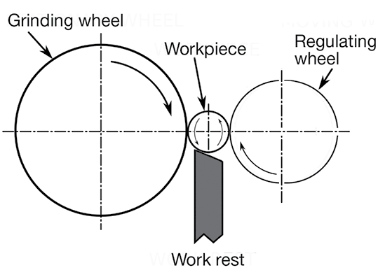
Fig 11Effects of honing pressure on MRR and surface finish
3.10.2 Lapping
Lapping is regarded as the oldest method of obtaining a fine finish. Lapping is an abrasive process in which loose abrasives function as cutting points finding momentary support from the laps. Figure 30.1 schematically represents the lapping process. Material removal in lapping usually ranges from .003 to .03 mm but many reach 0.08 to 0.1mm in certain cases.
Characteristics of the lapping process:
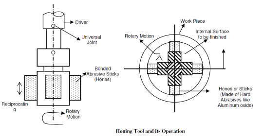
FIG 12
Abrasives of lapping:
Vehicle materials for lapping
Technical parameters affecting lapping processes
Lapping is performed either manually or by machine. Hand lapping is done with abrasive powder as a lapping medium, whereas machine lapping is done either with abrasive powder or with a bonded abrasive wheel.
Hand lapping
Hand lapping of the flat surface is carried out by rubbing the component over the accurately finished flat surface of the master lap usually made of a thick soft close-grained cast-iron block. Abrading action is accomplished by very fine abrasive powder held in a vehicle. Manual lapping requires high personal skill because the lapping pressure and speed have to be controlled manually.
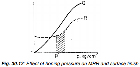
Fig 13
Lapping Machine
Machine lapping is meant for the economic lapping of batch qualities. In machine lapping, where high accuracy is demanded, metal laps and abrasive powder held in suitable vehicles are used. Bonded abrasives in the form wheel are chosen for commercial lapping. Machine lapping can also employ abrasive paper or abrasive cloth as the lapping medium. Production lapping of both flat and cylindrical surfaces are illustrated in Fig. 30.3 (a) and (b). In this case, a cast iron plate with loose abrasive carried in a vehicle can be used. Alternatively, bonded abrasive plates may also be used. Centreless roll lapping uses two cast iron rolls, one of which serves as the lapping roller twice in diameter than the other one known as the regulating roller. During lapping the abrasive compound is applied to the rolls rotating in the same direction while the workpiece is fed across the rolls. This process is suitable for lapping a single piece at a time and mostly used for lapping plug gauges, measuring wires, and similar straight or tapered cylindrical parts
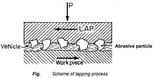
Fig 14 production lapping on (a) flat surface (b) cylindrical surface
3.10.3 Polishing
What is Polishing?
Polished Surface Functions
Types of Polishing
Lapping vs. Polishing
LappingHow Does Polishing Work?
Lapping vs. Polishing Systems
Key points
1) Honing is a finishing process, in which a tool called hone carries out a combined rotary and reciprocating motion while the workpiece does not perform any working motion.
2) Polishing normally takes place using a pad and slurry, the surface tension is quite high compared to lapping
3) Besides, a polished part features a much higher level of surface tension compared to a lapped part.
4) Lapping is performed either manually or by machine. Hand lapping is done with abrasive powder as a lapping medium, whereas machine lapping is done either with abrasive powder or with a bonded abrasive wheel.
References:
1. Kalpakjian and Schmid, Manufacturing processes for engineering materials (5th Edition)-Pearson India, 2014.
2. Mikell P. Groover, Fundamentals of Modern Manufacturing: Materials, Processes, and Systems.
3. Manufacturing Technology by P.N. Rao., MCGRAW HILL INDIA.
4. Materials and Manufacturing by Paul Degarmo.
5. Manufacturing Processes by Kaushish, PHI.
6. Principles of Foundry Technology, Jain, MCGRAW HILL INDIA
7. Production Technology by RK Jain.
8. Degarmo, Black &Kohser, Materials and Processes in Manufacturing.


