Unit V
Unconventional Machining Processes
This material is removed by fine abrasive particles (aluminium oxide or silicon carbide) carried in a high-velocity stream of air, nitrogen, or carbon dioxide. Abrasive Jet Machining (AJM) is used for deburring, etching, and cleaning of hard, and brittle metals, alloys, and non-metallic materials.
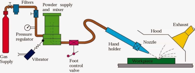
Fig 1 Abrasive jet machining
Abrasive jet machining (AJM) is one of the advanced machining processes (mechanical energy-based) where a high-velocity jet of abrasives is utilized to remove material from the work surface by impact erosion. The abrasive jet is obtained by accelerating fine abrasive particles in highly pressurized gas (carrier gas). A nozzle is used to convert this pressure energy into kinetic energy, and also to direct the jet towards the work surface at a particular angle (impingement angle). Upon impact, hard abrasive particles gradually remove material by erosion, and sometimes assisted by brittle fracture.
AJM differs from the age-old sandblasting technique by the achievable level of accuracy, and precision. AJM utilizes various abrasives including alumina, silicon carbide, glass beads, sodium bicarbonate, etc.; whereas sandblasting predominantly utilizes only silica sand (SiO2). Although the purposes of both the processes are quite identical, cutting parameters are often controlled precisely in AJM, and thus it can provide better accuracy, and precision.
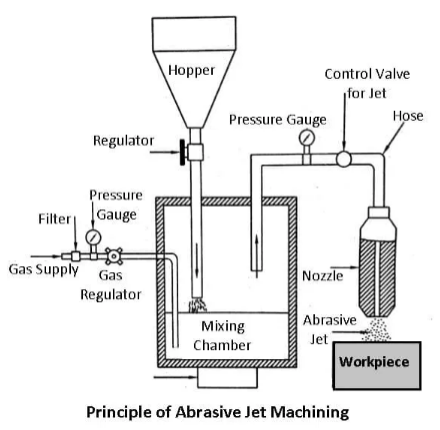
Fig 2
Working Principle of Abrasive Jet Machining
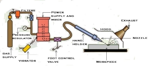
The figure shows a schematic diagram of the abrasive jet machine.
The filtered gas, supplied under a pressure of 2 to 8 kgf/cm to the mixing chamber containing the abrasive powder, and vibrating at 50 Hz entrains the abrasive particles, and is then passed into a connecting hose. This abrasive, and gas mixture emerges from a small nozzle mounted on a fixture at a high velocity ranging from 150 to 300 m/min.
Abrasive
Abrasive powder feed rate is controlled by the amplitude of vibration of the mixing chamber. The gas flow, and pressure are controlled by a pressure regulator. To control the size, and shape of the cut either the workpiece or the nozzle is moved by cams, pantographs, or other suitable mechanisms.
The abrasives generally used are silicon carbide, aluminium oxide, glass powder, or specially prepared sodium bicarbonate. The common particle sizes vary from 10 microns to 50 microns. Smaller sizes are used for good surface finish, and precision work. While larger sizes are used for rapid removal rate.
In addition to the above abrasives, dolomite (calcium magnesium carbonate) of 200 grit size is found suitable for light cleaning, and etching. Glass beads of diameter 0.30 to 0.60 mm are used for light polishing, and deburring.
Nozzle
Nozzles have a great degree of abrasion wear; they’re made of hard materials such as tungsten carbide or synthetic sapphire to reduce the wear rate. Nozzles made of tungsten carbide have an average life of 8 to 12 hours. While nozzles of sapphire last for about 300 hours of operation when used with 27-micron abrasive powder. The gases used are nitrogen, carbon dioxide, or clean air.
The metal removal rate depends upon the diameter of the nozzle, the composition of the abrasive gas mixture, the hardness of abrasive particles, and that of work material, particle size, the velocity of jet, and distance of the workpiece from the jet. A typical material removal rate for abrasive jet machining is 16 mm/min in cutting glass.
Fig 3
With close control of the various parameters, dimensional tolerance of +0.05 mm is often obtained. On normal production work, the accuracy of +0.1 mm is easily held.
Material removal is done with cutting speeds between 25 – 125 mm/min.
Dimensional tolerances are in the range of ± 2 to ± 5 µm
Process parameters, and their influence on AJM
(i) material removal rate (MRR),
(ii) surface roughness, and accuracy of machined feature, and
(iii) nozzle life or nozzle wear rate. Effects of process parameters on AJM performance are discussed below.
Effects of abrasives on AJM performance
Effects of carrier gas on AJM performance
Effects of mixing ratio on AJM performance
Effect of stand-off distance on AJM performance
Effect of impingement angle on AJM performance
Material removal rate, and its estimation
The processing capability of abrasive jet machining
Advantages of abrasive jet machining
Disadvantages of abrasive jet machining
Key points:
1) Abrasive jet machining (AJM) is one of the advanced machining processes (mechanical energy-based) where a high-velocity jet of abrasives is utilized to remove material from the work surface by impact erosion.
2) many factors can influence abrasive jet machining performance. Important process parameters include
(i) abrasive particles—its shape, size, strength, material, and flow rate;
(ii) carrier gas—its nature, composition, flow rate, pressure, and temperature;
(iii) abrasive jet—mixing ratio, striking velocity, impingement angle, and stand-off distance;
(iv) nozzle-its profile, and inner diameter;, and
(v) work material—its mechanical properties, and stress concentration
5.2 Water Jet Machining
The process is suitable for cutting, and deburring a variety of materials such as polymers, paper, and brick in thicknesses ranging from 0.03 to 1 in (0.8 to 25 mm) or more. The cut can be started at any location, wetting is minimal, and no deformation of the rest of the piece takes place.
5.3 Abrasive Water Jet Machining
Abrasives can be added to the water stream to increase the material removal rate, and this is known as abrasive water jet machining (AWJM).
Abrasive water jet cutting is an extended version of water jet cutting; in which the water jet contains abrasive particles such as silicon carbide or aluminium oxide to increase the material removal rate above that of water jet machining. Almost any type of material ranging from hard brittle materials such as ceramics, metals, and glass to extremely soft materials such as foam, and rubbers can be cut by abrasive water jet cutting. The narrow cutting stream and computer-controlled movement enables this process to produce parts accurately, and efficiently. This machining process is especially ideal for cutting materials that cannot be cut by laser or thermal cut. Metallic, non-metallic, and advanced composite materials of various thicknesses can be cut by this process. This process is particularly suitable for heat-sensitive materials that cannot be machined by processes that produce heat while machining.
The schematic of abrasive water jet cutting is shown in Figure 15 which is similar to water jet cutting apart from some more features underneath the jewel; namely abrasive, guard, and mixing tube. In this process, high-velocity water exiting the jewel creates a vacuum that sucks abrasive from the abrasive line, which mixes with the water in the mixing tube to form a high-velocity beam of abrasives.
Applications
Abrasive water jet cutting is highly used in the aerospace, automotive, and electronics industries. In aerospace industries, parts such as titanium bodies for military aircraft, engine components (aluminium, titanium, and heat resistant alloys), aluminium body parts, and interior cabin parts are made using abrasive water jet cutting.
In automotive industries, parts like interior trim (headliners, trunk liners, and door panels), and fiberglass body components, and bumpers are made by this process. Similarly, in electronics industries, circuit boards, and cable stripping are made by abrasive water jet cutting.
Advantages of abrasive water jet cutting
• In most of the cases, no secondary finishing required
• No cutter induced distortion
• Low cutting forces on workpieces
• Limited tooling requirements
• Little to no cutting burr
• Typical finish 125-250 microns
• Smaller kerf size reduces material wastages
• No heat-affected zone
• Localises structural changes
• No cutter induced metal contamination
• Eliminates thermal distortion
• No slag or cutting dross
• Precise, multi-plane cutting of contours, shapes, and bevels of any angle.
Limitations of abrasive water jet cutting
• Cannot drill flat bottom
• Cannot cut materials that degrade quickly with moisture
• Surface finish degrades at higher cut speeds which are frequently used for rough cuts
The major disadvantage s of abrasive water jet cutting is high capital cost and high noise levels during operation.
A component cut by abrasive water jet cutting is shown in Figure. As can be seen, large parts can but cut with very narrow kerfs which reduces material wastages. The complex shape part made by abrasive water jet cutting
Key points
Abrasives can be added to the water stream to increase the material removal rate, and this is known as abrasive water jet machining (AWJM).
5.4 Ultrasonic Machining - Principles, and Process parameters
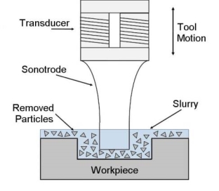
Fig 4 Ultrasonic machine
Working Principle of Ultrasonic Machining
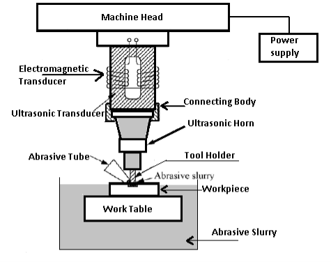
Fig 5
The Commonly Used Abrasives are
Accuracy
Limitations of the Process
Recent Development
Application of Ultrasonic Machining
The simplicity of the process makes it economical for a wide range of applications such as:
Advantages, and Disadvantages of Ultrasonic Machining
Advantages
Disadvantages
Process Parameters of USM, and Its Effect:
The important parameters that affect the process are the:
(i) Frequency:
The MRR increases linearly with the frequency. In practice also, the MRR raises with the frequency (see Fig.) but the actual characteristic is not exactly linear. The MRR tends to be lower than the theoretically predicted value.
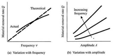
Fig 6 Graph between MRR and frequency/MRR and Amplitude
(ii) Amplitude:
When the amplitude of vibration is increased, the MRR is expected to increase, as are often seen from relation. The actual nature of the variation is as shown in Fig. for different values of the frequency. Again, the actual characteristic is somewhat different from the theoretically-predicted one. The main source of discrepancy stems from the fact that we calculated the duration of penetration Δt by considering the average velocity (=A/(T/4)). The characteristic of variation of Δt, given by –
is quite different from that obtained from the approximate expression, i.e., (h / A)(T / 4).
(iii) Static Loading (Feed Force):
With an increase in static loading (i.e., the feed force), the MRR tends to increase. However, in practice, it tends to decrease beyond a certain critical value of the force as the grains start getting crushed. The nature of variation of the MRR with the feed force (for various amplitudes) is shown in Fig. 6.17a.
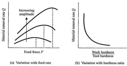
Fig 7 Graph between MRR and feed rate/MRR and hardness ratio
(iv) Hardness Ratio of the Tool, and the Work Piece:
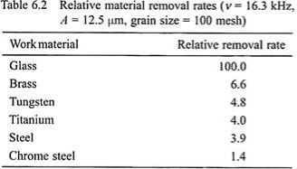
The ratio of the workpiece hardness and the tool hardness affects the MRR quite significantly, and the characteristic is as shown in Fig. 6.17b. Apart from the hardness, the brittleness of the work material plays a very dominant role. Table 6.2 indicates the relative material removal rates for different work materials, keeping the other parameters the same. A more brittle material is machined more rapidly.
(v) Grain Size:
Relation (6.18) indicates that the MRR should rise proportionately with the mean grain diameter d. However, when d becomes too large, and approaches the magnitude of the amplitude A, the crushing tendency increases, resulting in a fall in the MRR as shown in Fig. 6.18a.
(vi) Concentration of Abrasive in the Slurry:
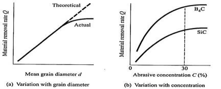
Fig 8 Material removal rate characteristics in USM
Key points
1) The maximum speed of penetration in soft, and brittle materials such as soft ceramics are of the order of 20 mm min.
2) for hard, and tough materials, the penetration rate is lower. Dimensional accuracy up to t0.005 mm is possible, and surface finishes down to a Ra value of 0.1-0.125 micron are often obtained.
5.5 Electrical Discharge Machining - Principle, and Processes parameters
Working Principle
In an Electrical discharge machining, a potential difference in form of pulses is
Applied across the tool and workpiece. The tool and workpiece must be electrically conductive, and a small gap must be maintained between them. The tool and workpiece are immersed in a dielectric medium like kerosene or deionized water. As the potential difference is increased, electrons from the tool begin to move towards the workpiece. Here the tool is negative, and the workpiece is positive. The electrons moving from the tool towards the workpiece collide with the molecules of the dielectric medium. Because of this collision of electrons with the molecule, it gets converted into ions. This increases the concentration of electrons, and ions in the gap maintained between the tool and workpiece. The electron moves towards the workpiece, and ions towards the tool. An electric current is set up in between the tool, and workpiece that forms a plasma. Like the electrons, and ions strike the workpiece, and tool respectively, their kinetic energy changes to heat energy. The temperature of the heat produced in that zone is about 10000 Deg. Celsius this resulting heat vaporizes and melts the material from the workpiece. As voltage breaks down, the current stops to flow between the tool, and workpiece, and the molten material in the workpiece is flushed by circulating dielectric medium leaving behind a crater.
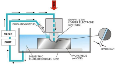
Fig 9 Electrical Discharge Machining
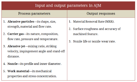
Fig 10
Types of Electrical Discharge Machine
There are two basic types of EDM machine
(i) Ram/Sinker EDM: This type of EDM machine consists of tools and workpieces that are immersed in a dielectric medium. It consists of a ram-type tool that may be created according to the shape or form required to be produced on the workpiece. It is also known as cavity-type or volume EDM.
(ii) Wire EDM: In wire EDM, a thin single-strand wire is generally used to cut the material from the workpiece. The wire is usually made-up of brass. A constant gap is always maintained between the wire and workpiece. The wire is continuously fed through the workpiece that is submerged in a tank with the dielectric medium. The spark is generated in the gap between the wire, and workpiece which is used to cut metal as thick as 300 mm, and to make punches, dies, and tools from hard metals that are very difficult to cut from other methods.
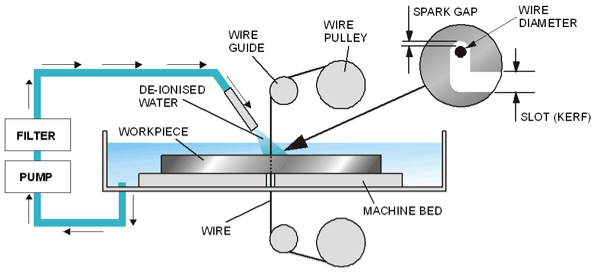
Fig 11 Wire EDM
Equipment
Various equipment that is used in Electrical Discharge Machining is
1. Dielectric Reservoir, Pump, and Circulating systemThe pump is generally used to circulate the dielectric medium between the two electrodes (tool, and workpiece), and Kerosene or deionized water is used as a dielectric medium.
2. Power Generator, and Control UnitThe generator is typically used to apply the potential difference, and the voltage used in this machining process is not constant but it is applied in pulse form. A control unit is also used to control the different operations during a machining process.
3. Working Tank with Work Holding DevicesThe setup has a working tank with a work-holding device that holds the workpiece. The tank contains a dielectric medium.
4. Tool HolderIt is used to hold the tool.
5. Servo System to Move the ToolA servo system is used to control the tool that helps to maintain the necessary gap between the electrodes (tool, and workpiece).
Characteristics of EDM
Working of Electrical Discharge Machining (EDM)
Process Parameters
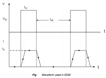
Fig 12
The waveform is characterized by the
• The open-circuit voltage - Vo
• The working voltage - Vw
• The maximum current - Io
• The pulse on time – the duration for which the voltage pulse is applied - ton
• The pulse of time - toff
• The gap between the workpiece, and the tool – spark gap - δ
• The polarity – straight polarity – tool (-ve)
• The dielectric medium
• External flushing through the spark gap.
Advantages
Disadvantages
Application
Key points
Electrical Discharge Machining (EDM) is a non-traditional machining process, and also an electrothermal process in which material from the workpiece is removed typically by using electrical discharges
5.6 MRR, and Surface finish
5.6.1 MRR
5.6.2 Surface finish
Surface finish is also known as surface texture or surface topography, is the nature of a surface. It comprises the small local deviations of a surface from the perfectly flat ideal (a true plane). The surface of every component has some form of texture which varies according to its structure and the way it has been manufactured.
To control the manufacturing process or predict a component’s behaviour during use, it is necessary to quantify surface characteristics by using surface texture parameters.
Surface texture parameters or surface finish parameters can be separated into three basic types:
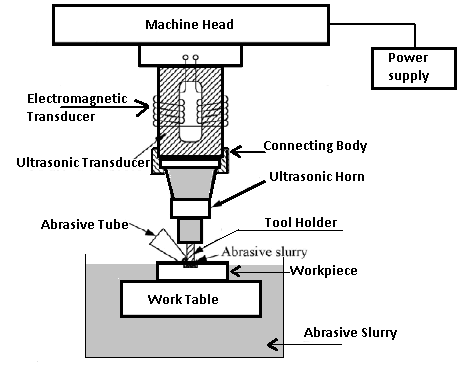
Fig 13
Initial surface waviness and defects are not greatly altered in contouring most metals but may be smoothened out to a certain extend. The quality of finish is lower for extrusions, forgings, and castings. The surface finish obtained maybe around 5 μm. Aluminium alloys show a better surface of the order of 1.6 μm. Hydrogen embrittlement may occur owing to the absorption of hydrogen in chemical machining in some metals.
Aluminium alloys are not subjected to hydrogen embrittlement. Considerable care should be taken to avoid hydrogen embrittlement in steel, stainless steel, copper alloys, and nickel alloys. If hydrogen embrittlement occurs, it can be overcome by heating the workpiece at 1200 C for 1 to 4 hours. The surfaces produced by the CHM process otherwise stress-free and show no thermal effects. Surface finish depends on the surface quality of the original workpiece. On most materials, scratches, and local damage will be reproduced, and magnified. Chemical milling removes small defects or scratches in magnesium, and to some extent in steel, and titanium sheets. At deeper etching, the influence of the original work surface diminishes, the surface finish produced being nearer to the typical finish for a particular work material, which has
Undergone a particular history of heat treatment, and for a particular etchant formulation, and etching parameters. Here is a list of elements, and their surface finish after 0.25-0.40mm removed from the surface.
Types of Surface Finish Parameters (Surface Texture Parameters)
Surface texture or surface finish parameters can be separated into three basic types:
Amplitude parameters
Spacing parameters
Hybrid parameters
Key points
Surface finish is also known as surface texture or surface topography, is the nature of a surface. It comprises the small local deviations of a surface from the perfectly flat ideal (a true plane).
5.7 Tool wear
Cutting tools are subjected to an extremely severe rubbing process. They are in metal-to-metal contact between the chip, and the workpiece, under high stress, and temperature. The situation becomes severe due to the existence of extreme stress, and temperature gradients near the surface of the tool.
Tool wear is generally a gradual process due to regular operation. Tool wear can be compared with the wear of the tip of an ordinary pencil. According to the Australian standard, tool wear can be defined as “The change of shape of the tool from its original shape, during cutting, resulting from the gradual loss of tool material”.
Tool wear depends upon the following parameters:
i. Tool and workpiece material.
ii. Tool shape.
iii. Cutting Speed.
iv. Feed.
v. Depth of cut.
vi. Cutting fluid used.
vii. Machine Tool characteristics etc.
Tool wear affects the following items:
i. Increased cutting forces.
ii. Increased cutting temperature.
iii. Decreased accuracy of produced parts.
iv. Decreased tool life.
v. Poor surface finish.
vi. Economics of cutting operations.
Types of Tool Wear:
The high contact stresses are developed in the machining process due to rubbing action of:
(i) Tool rake face, and chips.
(ii) Tool flank face, and machined surface.
These results in a variety of wear patterns observed at the rake face, and the flank face. We call this gradual wear of the tool. The gradual wear is unavoidable but controllable. It is wear which cannot be prevented. It has to occur after a certain machining time.
The gradual wear can be controlled by remedial action. The gradual wear can be divided into two basic types of wear, corresponding to two regions in the cutting tool as shown in Fig.14
These are the following:
(i) Flank wear.
(ii) Crater wear.
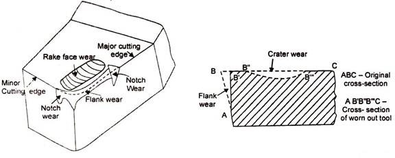
Fig 14(a) Tool wears phenomena Fig 14(b) Flank and crater wear
(i) Flank Wear:Wear on the flank face (relief or clearance face) of the tool is called flank wear. The flank wear is shown in Fig.15 (a, b, c).
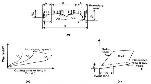
Fig 15 (a, b, c)
The characteristics of flank wear are the following:
i. It is the most important wear that appears on the flank surface parallel to the cutting edge. It is most commonly results from abrasive/adhesive wear of the cutting edge against the machined surface.
ii. It generally results from high temperatures, which affect tool, and work material properties.
iii. It results in the formation of wear land. Wear land formation is not always uniform along with the major, and the minor cutting edge of the tool.
iv. It can be measured by using the average wear land size (V3), and maximum wear land size (VBmax).
v. It can be described using the Tool Life Expectancy Equation.
VCTn = C
A more general form of the equation (considering the depth of cut, and feed rate) is
VcTnDxFy = C
Where,
Vc = Cutting Speed
T = Tool life
D = Depth of cut (mm)
F = Feed rate (mm/rev. or inch/rev.)
x, and y = Exponents that are determined experimentally for each cutting condition.
C = Machining constant, found by experimentation or published databook. Depends on the properties of tool materials, workpiece, and feed rate.
n = exponential
Values of n = 0.1 to 0.15 (For HSS tools)
= 0.2 to 0.4 (For carbide tools)
= 0.4 to 0.6 (For ceramic tools)
Reasons for Flank Wear:
i. Increased cutting speed causes flank to wear to grow rapidly.
ii. Increase in feed, and depth of cut can also result in larger flank wear.
iii. Abrasion by hard panicles in the workpiece.
iv. Shearing of micro welds between tool, and work-material.
v. Abrasion by fragments of built-up edge, which strike against the clearance face (Flank face) of the tool.
Remedies for Flank Wear:
i. Reduce cutting speed.
ii. Reduce feed, and depth of cut.
iii. Use a hard grade of carbide if possible.
iv. Prevent formation of built-up edge, using chip breakers.
Effects of Flank Wear:
i. Increase in the total cutting force.
ii. Increase in component surface roughness.
iii. Also affects the component dimensional accuracy.
iv. When form tools are used, flank wear will also change the shape of the components produced,
(ii) Crater Wear:Wear on the rake face of the tool is called crater wear. As the name suggests, the shape of wear is that of a crater or a bowl. The crater wear is shown in Fig.16 ,17.
Fig 16 Crater wear
Fig 17
The characteristics of crater wear are the following:
i. In crater wear chips erode the rake face of the tool.
ii. The chips that flow across the rake face develop severe friction between the chip and the rake face. This produces a scar on the rake face which is usually parallel to the major cutting edge.
iii. It is somewhat normal for tool wear, and does not seriously degrade the use of a tool until it becomes serious enough to cause a cutting edge failure.
iv. The crater wear can increase the working rake angle, and reduce the cutting force, but it will also weaken the strength of the cutting edge.
v. It is more common in ductile materials like steel which produce long continuous chips. It is also more common in H.S.S. (High-Speed Steel) tools than ceramic or carbide tools which have much higher hot hardness.
vi. The parameters used to measure the crater wear can be seen in Fig.5.7. The crater depth KT is the most commonly used parameter in evaluating the rake face wear.
vii. It occurs approximately at a height equal to the cutting depth of the material, i.e., Crater wears depth ⋍ cutting depth.
viii. At high-temperature zones (nearly 700°C) create wear occurs.
Reasons for Crater Wear:
i. Severe abrasion between the chip-tool interfaces, especially on the rake face.
ii. High temperature in the tool-chip interface.
iii. Increase in feed results in an increased force acting on the tool interface, this leads to a rise in temperature of the tool-chip interface.
iv. Increase in cutting speed results in increased chip velocity at the rake face, this leads to a rise in temperature at the chip-tool interface, and so an increase in crater wear.
Remedies for Crater Wear:
i. Use of proper lubricants can decrease the abrasion process, and so decrease crater wear.
ii. Proper coolant for rapid heat dissipation from the tool-chip interface.
iii. Reduced cutting speeds, and feed rates.
iv. Use tougher and hot hardness materials for tools.
v. Use positive rake tool.
Causes of Tool Wear:
There are large numbers of causes for tool wear.
Some of them are important to discuss here from the subject point of view:
(i) Abrasive wears (Hard particle wear).
(ii) Adhesive wear.
(iii) Diffusion wears.
(iv) Chemical wear.
(v) Fracture wear.
(i) Abrasive Wear (Hard Particle Wear):Abrasive wear is caused by the impurities within the workpiece material, such as carbon nitride, and oxide compounds, as well as the built-up edge fragments. It is a mechanical type of wear. It is the main cause of the tool wear at low cutting speeds.
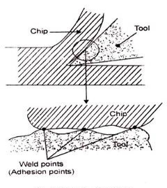
(ii) Adhesive Wear:Due to high pressure, and temperature at the tool-chip interface, there is a tendency of hot chips to weld onto the tool rake face. This concept leads to the subsequent formation, and destruction of welded junctions. When the weld intermittently breaks away picking particles of the cutting tool. This leads to crater wear. Fig. 9.19 shows adhesive wear.
Fig 18 Adhesive wear
(iii) Diffusion Wear:
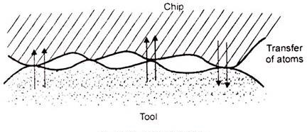
Diffusion wear is usually caused by atomic transfer between contacting materials under high pressure, and temperature conditions. This phenomenon starts at the chip-tool interface. At such elevated temperatures, some particles of tool materials diffuse into the chip material. It can also happen that some particles of work material also diffuse into the tool materials.
This exchange of particles changes the properties of tool material, and causes wear, as shown in Fig. 14:
Fig 19 Diffusion wear
This diffusion results in changes in the tool, and workpiece composition.
There are several ways of diffusions like:
(a) Gross Softening of the Tool:
Diffusion of carbon in a relatively deep surface layer of the tool may cause softening, and subsequent plastic flow of the tool. It may produce major changes in tool geometry.
(b) Diffusion of Major Tool Constituents into the Work:
The tool matrix or a major strengthening constituent may be dissolved into the work, and chip surfaces as they pass the tool. For example Demand tool, cutting iron, and steel is the typical examples of carbon diffusion.
(c) Diffusion of a Work Material Component into the Tool:
A constituent of the work material diffusing into the tool may alter the physical properties of a surface layer of the tool. For example, The diffusion of lead into the tool may produce a thin brittle surface layer, this thin layer can be removed by chipping.
(iv) Chemical Wear:The chemical wear is caused due to a chemical attack on a surface.
For example:
Corrosive wear.
(v) Facture Wear:The facture wear is usually caused by breaking of the edge at end or length. The bulk breakage is the most harmful, and undesirable type of wear, and it should be avoided as far as possible.
Growth of Tool Wear:
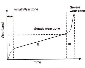
The growth pattern of tool wear is shown in Fig. 20:
Fig 20 Growth of tool wear
We can divide the growth into the following three zones:
(i) Severe wear zone.
(ii) Initial Wear zone.
(iii) Severe or ultimate or catastrophic wear zone.
(i) Initial Preliminary or Rapid Wear Zone:Initially, for the new cutting edge, the growth of wear is faster. The initial wear size is VB = 0.05 to 0.1 mm normally.
The causes of initial or rapid wear are:
i. Microcraking.
ii. Surface oxidation.
iii. Carbon loss layer.
iv. Micro-roughness of tooltip grinding.
(ii) Steady Wear Zone:After the initial wear, we found that the wear rate is relatively steady or constant. In this zone, the wear size is proportional to the cutting time.
(iii) Severe or ultimate or catastrophic Wear Zone:In this zone, the rate of growth of wear is much faster, and result in catastrophic failure of the cutting edge.
When the wear size increases to a critical value, the surface roughness of the machined surface decreases, cutting force, and temperature increases rapidly, and the wear rate increases. Then the tool loses its cutting ability. In practice, this zone of wear should be avoided.
Allowable Wear Land:
As we decide to sharpen a knife-edge when the quality of the cut begins to deteriorate, and the cutting forces required increase too much, similarly re-sharpen or replace cutting tools when.
(a) The quality of the machined surface begins to deteriorate.
(b) The cutting forces increase significantly.
(c) Pre-temperature rise significantly.
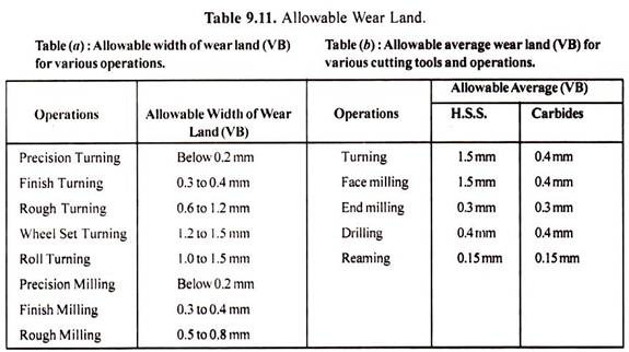
The average width of allowable flank wear varies from 0.2 mm (for a precision turning operation) to 1 mm (for a rough turning operation).
The following Table 9.11 gives some recommended values of allowable average wear land (VB) for various operations, and cutting tools:
Forms of Tool Wear:
Flank and crater wear are a very common type of wears.
Some other forms of tool wear are:
(i) Thermo-Electric Wear.
(ii) Thermal Cracking, and Tool Fracture.
(iii) Cyclic Thermal, and Mechanical Load Wear.
(iv) Edge Chipping.
(v) Entry or Exit Failures.
(i) Thermo-Electric Wear:It can be observed in the high-temperature region. The high-temperature results in the formation of a thermal-couple between the workpiece, and the tool.
Due to this effect voltage established between the workpiece, and tool. It may cause an electric current flow between the two. However, this type of wear has not been developed.
(ii) Thermal Cracking, and Tool Fracture:It is common in the case of the milling operation. In milling, tools are subjected to cyclic thermal, and mechanical loads. Teeth may fail by a mechanism not observed in continuous cutting. Thermal cracking can be reduced by reducing the cutting speed or by using a tool material grade with higher thermal shock resistance.
(iii) Cyclic Thermal, and Mechanical Load Wear:The cyclic variation in temperature in the milling process induces cyclic thermal stress at the surface layer of the tool expands and contracts. It may lead to the formation of thermal fatigue cracks near the cutting edge.
Mostly, such cracks are perpendicular to the cutting edge, and begin formation at the outer corner of the tool, spreading inward as cutting progress. The growth of these cracks eventually leads to edge chipping or tool breakage. An insufficient coolant can promote crack formation.
(iv) Edge Chipping:Edge chipping is commonly observed in milling operations. It may occur when the tool first contacts the part (Entry Failure) or, more commonly, when it exits the part (Exit Failure).
(v) Entry or Exit Failures:Entry failure most commonly occurs when the outer corner of the insert strikes the part first. This is more likely to occur when the cutter rake angles are positive. Entry failure is therefore most easily prevented by switching from positive to negative rake angle cutters.
Consequences (Effects) of Tool Wear:
The effects of the tool wear on technological performance are the following:
(i) Increase in Cutting Forces:The cutting forces are normally increased by the wear of the tool. Crater wear, flank wear (or wear land formation), and chipping of cutting edge affect the performance of the cutting tool in various ways. Crater wear may, however under certain circumstances, reduce forces by effectively increasing the rake angle of the tool. Clearance face (Flank or wear-land) wear, and chipping almost invariably increase the cutting forces due to increased rubbing forces.
(ii) Increase in Surface Roughness:As the tool wear increases, the surface roughness of the machined component also increases. This is particularly true for a tool worn by chipping. Although, there are circumstances, in which a wear land may burnish (polish) the workpiece, and produce a good finish.
(iii) Increase in Vibration or Chatter:Vibration or chatter is another important aspect of the cutting process which may be influenced by tool wear.
A wear land increases the tendency of a tool to dynamic instability or vibrations. When the tool is sharp, the cutting operation is quite free of vibrations. On the other hand, when the tool wears, the cutting operation is subjected to an unacceptable vibration, and chatter mode.
(iv) Decreases in Dimensional Accuracy:Due to flank wear, the plan geometry of a tool may disturb. This may affect the dimensions of the component produced. It may influence the shape of the component.
5.8 Dielectric
Dielectric, insulating material or a very poor conductor of electric current. When dielectrics are placed in an electric field, practically no current flows in them because, unlike metals, they have no loosely bound, or free, electrons that may drift through the material. Instead, electric polarization occurs. The positive charges within the dielectric are displaced minutely in the direction of the electric field, and the negative charges are displaced minutely in the direction opposite to the electric field. This slight separation of charge, or polarization, reduces the electric field within the dielectric.
The presence of dielectric material affects other electrical phenomena. The force between two electric charges in a dielectric medium is less than it would be in a vacuum, while the quantity of energy stored in an electric field per unit volume of a dielectric medium is greater. The capacitance of a capacitor filled with a dielectric is greater than it would be in a vacuum. The effects of the dielectric on electrical phenomena are described on a large, or macroscopic scale by employing such concepts as dielectric constant, permittivity (qq.v.), and polarization.
5.9 Power, and control circuits
Generally, a power circuit’s job is to provide power for the operation of other circuits. This could include a power source like a battery or it may receive power from an external source. Power circuits typically must handle higher power levels than other types of circuits, and as a result, may require cooling elements like heat sink or fans that increase the cost of the design. Committing design efforts to improve efficiency in power circuits is often worth the effort to improve reliability, and reduce over-all package size.
Control circuits typically take some type of input and provide some type of output. A common type of control circuit is a voltage regulator. The voltage regulator provides a constant output voltage by sampling the output voltage and adjusts it until it makes a reference voltage. Many power circuits utilize this type of control circuit to provide clean power for the operation of the device.
A very different type of control circuit is using a CPU to control reading one or more inputs, and settings one or more output signals as the result of the instructions in the firmware. The is a type of control circuit that can perform much more complicated operations than a typical fixed electronics control circuit. As an example, a CPU could be used in a voltage regulation circuit to provide smart over-current protection. A typical analog voltage regulator will either shut down or stop providing full voltage when loaded beyond the set limits of the circuit. Over-temperature protection is also a common feature of an analog voltage regulator. However, a CPU control regulator can provide some abilities such as:
Because control circuits are often contained in power circuits their is often not a clear line between the two circuits.
5.10 Wire EDM
In wire EDM, a thin single-strand wire is generally used to cut the material from the workpiece. The wire is usually made-up of brass. A constant gap is always maintained between the wire and workpiece. The wire is continuously fed through the workpiece that is submerged in a tank with the dielectric medium. The spark is generated in the gap between the wire, and workpiece which is used to cut metal as thick as 300 mm, and to make punches, dies, and tools from hard metals that are very difficult to cut from other methods.
5.11 Electrochemical machining (ECM)
NaCl ↔ Na+ + Cl-
H2O ↔ H+ + (OH)
2H+ + 2e- = H2↑ at cathode
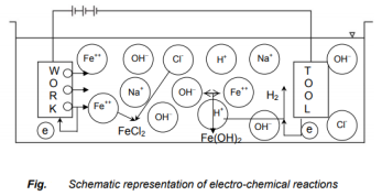
Fig 21
• The electrode potential
• The activation over potential
• Osmic potential drop
• Concentration over potential
• Ohmic resistance of the electrolyte
Main Equipment of ECM
The ECM system has the subsequent modules
Working Process
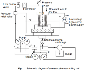
Fig 5.22
Process Parameter
S.no | Parameters | Values |
1. | Power Supply |
|
| Type | Direct Current |
| Voltage | 2 to 35 V |
| Current | 50 to 40,000 A |
| Current Density | 0.1 A/mm2 to 5 A/mm2 |
2. | Electrolyte |
|
| Material | NaCl, and NaNO3 |
| Temperature | 20 oC to 50 oC |
| Flow rate | 20 lpm/100 A current |
| Pressure | 0.5 to 20 bar |
| Dilution | 100 g/l to 500 g/l |
3. | Working gap | 0.1 mm to 2mm |
4. | Overcut | 0.2 mm to 3 mm |
5. | Feed rate | 0.5 mm/min to 15 mm/min |
6. | Electrode material | Copper, brass, and bronze |
7. | Surface roughness (Ra) | 0.2 to 1.5 μm |
Application
Advantages
Disadvantages
5.12 Etchant & Maskant - Process parameters
Maskants
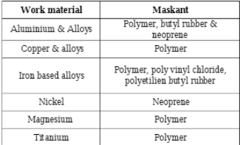
Masking material is known as Maskant which is used to protect workpiece surface from the chemical etchant.
In another word, maskants protect the portion of workpiece metal where the material is not to be removed by the chemical action of the etchant. Polymer or rubber-based materials are generally used as a maskant material. Various maskant application methods can be used such as dip, brush, spray, roller, and electro-coating as well as adhesive tapes.
The type of maskant to be selected for machining is based on the following factors
TABLE 1
Masking material for various work material
Etchants
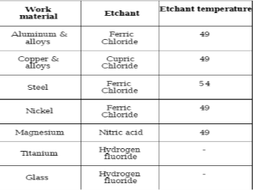
Etchants are acid or alkaline solutions maintained within a controlled range of chemical composition, and temperature. The workpiece material to be removed is sprayed or immersed in a suitable etchant. The various etchant is available for machining different material as listed in table 2. The type of etchant to be selected for machining is based on the following factor
Type of workpiece metal that is being etched
Rate of metal removal
Key points
1) Masking material is known as Maskant which is used to protect workpiece surface from the chemical etchant.
2) Etchants are acid or alkaline solutions maintained within a controlled range of chemical composition, and temperature
5.13 Laser Beam Machining (LBM)
Introduction
Laser Beam Machining – the lasing process
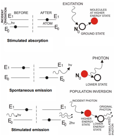
Fig 23
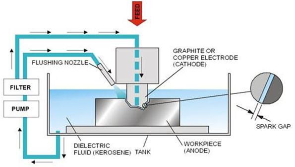
Fig 24
Lasing Medium
• Ruby is chromium – alumina alloy having a wavelength of 0.7 μm
• Nd-glass lasers having a wavelength of 1.64 μm
• Nd-YAG laser having a wavelength of 1.06 μm
- Helium-Neon
- Argon
- CO2 etc.
Lasers can be operated in continuous mode or pulse mode. Generally, the CO2 gas laser is operated in continuous mode, and Nd – YAG laser is operated in pulsed mode.
Laser Construction
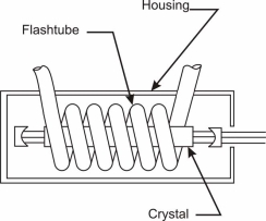
Fig. 25 Solid-state laser with its optical pumping unit
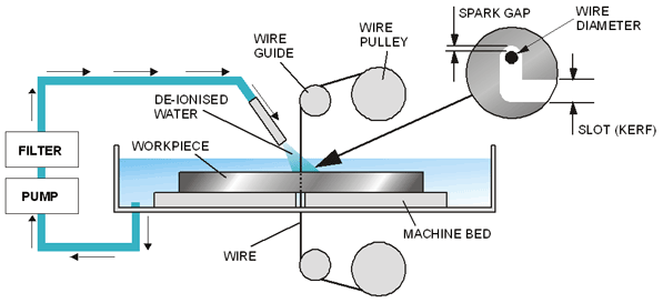
Fig. 26 Working of a solid-state laser
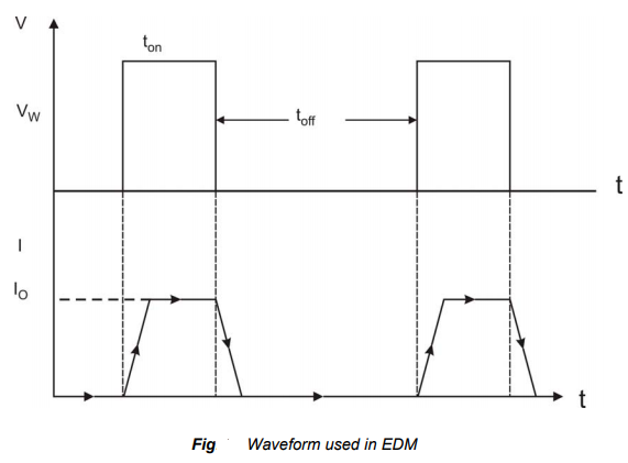
Fig. 27 Construction of a CO2 laser
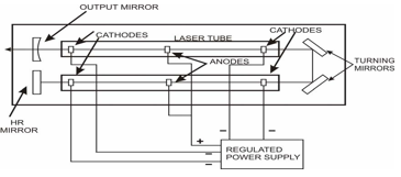
Fig. 28 Construction of folded gas laser
Laser Beam Machining – Application
The laser can be used in a wide spectrum of manufacturing applications
Laser Beam Machining – Advantages
Laser Beam Machining – Limitations
Identification of the Important Process Parameters in LBM
The peak power must be large enough to vaporize the workpiece. There exists a threshold value of laser beam intensity below which, no melting/vaporization will occur. When a laser without a gas jet heats a metal target, the energy absorbed is conducted into surrounding colder metal. The minimum amount of power impact necessary to initiate evaporation when it is exposed to laser radiation is known as threshold intensity.
Pulse duration or pulse width is defined as the time needed to vaporize the material. It should not be shorter than the penetration time of the laser beam. As the pulse energy increases the penetration time decreases
Because of the periodic nature of the heating, the mechanism of pulsed laser cutting is different from that of CW laser cutting. The overall effect of laser cutting in pulsed mode is identical to the overlapping of a series of drilling operations. Every pulse peak makes a hole in the workpiece. Cutting action is the process of an accumulation of the action of a series of single pulses. A higher frequency will increase the overlapping number and reduces the cut roughness. However, there’s an upper limit of pulse repetition frequency beyond which the pulse duration will be limited, and the pulse will approach a continuous wave. The inverse of the pulse frequency, that is, the pulse period should be larger than the pulse duration.
Sound and safe cutting results are practicable at feed rates of about 80 to 90% of the maximum possible cutting speed. For certain quality demands, the speed may have to be reduced. If the speed is too low, during fusion cutting dross formation, and during oxidation cutting burnouts can occur. These two defects are often avoided by pulsing the laser. In pulsed laser cutting, the displacement of the work-piece during a pulse cycle should be much smaller than the diameter of the focused spot, so that a continuous, and smooth machined surface is often obtained. Therefore, the pulsed laser cutting is often considered approximately as an accumulation of the actions of a series of single pulses
In laser fusion cutting, the focal position should be near the bottom plane of the workpiece to simplify dross prevention, and near or above the middle to maximize speed. In laser oxidation cutting, the focal point should be positioned in the upper half of the material. In the thick section range of 10mm or more the optimum focal position is often some millimeters above the workpiece. It is the distance between the workpiece and the focusing lens. It determines the diameter of the focused spot, and therefore the light concentration on the work surface.
In the fusion cutting, the pressure has to be high (up to 2Mpa), increasing with workpiece thickness. On the other hand, a certain upper limit must not be exceeded to avoid shielding plasma resulting in a kerf collapse. In oxidation cutting, typical pressure values are in the range of 0.1 to 0.5 MPa. In the case of thick (10mm or more) mild steel, the oxygen pressure should be below 0.08 MPa to avoid burn-outs.
Plasma-arc machining (PAM) employs a high-velocity jet of high-temperature gas to melt, and displace material in its path. Called PAM, this is a method of cutting metal with a plasma-arc, or tungsten inert-gas-arc, torch. The torch produces a high-velocity jet of high-temperature ionized gas called plasma that cuts by melting and removing material from the workpiece. Temperatures in the plasma zone range from 20,000° to 50,000° F (11,000° to 28,000° C).
What is Plasma
Solids, liquids, and gases are the three familiar states of matter. In general, when a solid is heated, it turns to liquids, and the liquids eventually become gases. When a gas is heated to a sufficiently high temperature, the atoms (molecules) are split into free electrons and ions. The dynamical properties of this gas of free electrons and ions are sufficiently different from the normal unionized gas. So, it can be considered
the fourth state of matter, and is given a new name, PLASMA’. In other words, when the following gas is heated to a sufficiently high temperature of the order of 11,000°C to 28,000°C, it becomes partially ionized, and it is known as ‘PLASMA’. This is a mixture of free electrons, positively charged ions, and neutral atoms.
This plasma is used for the metal removal process. The plasma arc machining process is used for cutting alloy steels, stainless steel, cast iron, copper, nickel, titanium, and aluminium, etc.
Working Principle of PAM
In the plasma arc machining process, the material is removed by directing a high-velocity jet of high temperature (11000°C to 28,000°C) ionized gas on the workpiece. This high-temperature plasma jet melts the material of the workpiece.
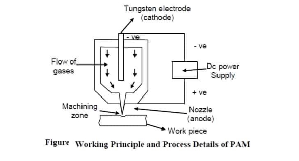 Fig 29 Plasma arc machining working principle diagram
Process Details of PAM
Details of PAM are described below.
Gases are used to create plasma-like, nitrogen, argon, hydrogen, or a mixture of these gases. The plasma gun consists of a tungsten electrode fitted in the chamber. The electrode is given negative polarity, and the nozzle of the gun is given positive polarity. The supply of gases is maintained in the gun. A strong arc is established between the two terminals anode and cathode. There is a collision between molecules of gas, and electrons of the established arc. As a result of this collision, gas molecules get ionized, and heat is evolved. This hot, and ionized gas called plasma is directed to the workpiece with high velocity. The established arc is controlled by the supply rate of gases.
Power supply (DC) is used to develop two terminals in the plasma gun. A tungsten electrode is inserted into the gun and made cathode, and the nozzle of the gun is made anode. Heavy potential difference is applied across the electrodes to develop a plasma state of gases.
As we know that hot gases continuously come out of the nozzle so there are chances of its overheating. A water jacket is used to surround the nozzle to avoid overheating.
there is no direct visible tool used in PAM. A focused spray of ho0t, plasma state gases works as a cutting tool.
The workpiece of different materials can be processed by the PAM process. These materials are aluminum, magnesium, stainless steel, and carbon, and alloy steels. All those materials which can be processed by LBM can also be processed by the PAM process.
Construction of Plasma arc Machining:
• The schematic arrangement of plasma arc machining is shown in Fig.
• The plasma arc cutting torch carries a tungsten electrode fitted in a small chamber.
• This electrode is connected to the negative terminal of a DC power supply. So it acts as a cathode. The positive terminal of a D.C power supply is connected to the nozzle formed near the bottom of the chamber. So, the nozzle acts as an anode.
• A small passage is provided on one side of the torch for supplying gas into the chamber.
• Since there is a water circulation around the torch, the electrode, and the nozzle remains water-cooled.
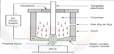
Fig 30 Construction of PAM
Working of PAM:
ACCURACY
• Plasma arc machining is a roughing operation to an accuracy of around 1.4 mm with the corresponding surface finish. Accuracy on
the width of slots, and the diameter of holes is ordinarily from ± 4 mm on 100 to 150 mm thick plates.
GASES USED IN PAM
The selection of a particular gas for use in this process mainly depends on the expected quality of surface finish on the work material, and economic consideration. The gases used in this process, should not affect the electrode or the workpiece to be machined. The commonly used gases, and gas mixtures are given in the following table.
Sr. No. | Gas or Gas Mixture | Material to be Machined |
1 | Nitrogen - Hydrogen, | Stainless steel, and non-ferrous metals. |
2 | Nitrogen - Hydrogen, | Carbon, and alloy steels, cast iron. |
3 | Nitrogen, | Aluminium, Magnesium |
STANDOFF DISTANCE
Stand-off distance is the distance between the nozzle tip and the workpiece. When the stand-off distance increases, the depth of penetration is reduced. With an excessive reduction of the stand-off distance, the plasma torch can be damaged by the metal spatter. The optimum
stand-off distance depends on the thickness of the metal being machined and varies from 6 to 10 mm.
ADVANTAGES OF PAM
DISADVANTAGES OF PAM
1. It produces a tapered surface.
2. The protection of noise is necessary.
3. The equipment cost is high.
4. Protection of eyes is necessary for the operator, and persons working in nearby areas.
5. Oxidation and scale formation takes place. So, it requires shielding.
6. The work surface may undergo metallurgical changes.
APPLICATIONS
1. It is used for cutting alloy steels, stainless steel, cast iron, copper, nickel, titanium, aluminum, and alloy of copper, and nickel, etc.
2. It is used for profile cutting.
3. It is successfully used for turning, and milling of hard to machine materials.
4. It can be used for stack cutting, shape cutting, piercing, and underwater cutting.
5. Uniform thin film spraying of refractory materials on different metals, plastics, ceramics are also done by plasma arcs.
CHARACTERISTICS OF PAM
Key points
1) Plasma-arc machining (PAM) employs a high-velocity jet of high-temperature gas to melt, and displace material in its path. Called PAM, this is a method of cutting metal with a plasma-arc, or tungsten inert-gas-arc, torch.
2) The plasma arc machining process is used for cutting alloy steels, stainless steel, cast iron, copper, nickel, titanium, and aluminums, etc.
Electron beam machining is a thermal process used for metal removal during the machining process. In electrical beam machining, electrical energy is used to generate electrons with high energy. In the Electron Beam Machining process, a high velocity focused beam of electrons is used to remove the metal from the workpiece. These electrons are traveling at half the velocity of light i.e., 1.6 x 10∧8 m / s. This process is best suited for the micro-cutting of materials.
Principle of EBM:
When the high-velocity beam of electrons strikes the workpiece, its kinetic energy is converted into heat. This concentrated heat raises the temperature of workpiece material, and vaporizes a small amount of it, resulting in the removal of material from the workpiece.
Types of EBM Process:
The following two methods are used in the EBM process.
1. Machining inside the vacuum chamber.
2. Machining outside the vacuum chamber.
Construction, and Working of Electron Beam Machining :
Construction of EBM:
1. Tungsten Filament — which is connected to the negative terminal of the DC power supply, and acts as the cathode.
2. Grid cup – which is negatively based concerning the filament.
3. Anode – which is connected to the positive terminal of the DC power supply?
EBM Diagram:
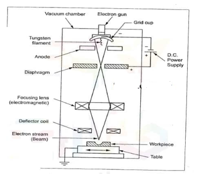
Fig 31 Electron beam machining diagram
Working of EBM:
travel through the vacuum.
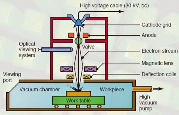 Fig 32 Electron beam machining Diagram
Machining Outside the Vacuum Chamber :
Since the full vacuum system is more costly, the recent development has made it possible to machine outside the vacuum chamber. In this arrangement, the necessary vacuum is maintained within the electron gun, and the gases are removed as soon as they enter the system.
Process Parameters:
The parameters which have a significant influence on the beam intensity, and metal removal rate are given below:
1. Control of current. –
2. Control of spot diameter.
3. Control of focal distance of the magnetic lens.
Characteristics Of EBM Processes:
Accelerating voltage | : 50 to 200 kV |
Beam current | : 100 to 1000 µA |
Electron velocity | : 1.6 x 10^8 m/s |
Power density | : 6500 billion W/mm^2 |
Medium | : Vacuum (10^-5 to 10^-6 mm of Hg) |
Workpiece material | : All materials |
Depth of cut | : Up to 6.5 mm |
Material removal rate | : Up to 40 mm^3 / s |
Specific power consumption | : 0.5 to 50 kW |
Advantages of EBM:
Electron beam machining has the following advantages:
Disadvantages of EBM: Limitation of EBM
Application of EBM:
References:
1. Kalpakjian and Schmid, Manufacturing processes for engineering materials (5th Edition)- Pearson India, 2014.
2. Mikell P. Groover, Fundamentals of Modern Manufacturing: Materials, Processes, and Systems.
3. Manufacturing Technology by P.N. Rao., MCGRAW HILL INDIA.
4. Materials and Manufacturing by Paul Degarmo.
5. Manufacturing Processes by Kaushish, PHI.
6. Principles of Foundry Technology, Jain, MCGRAW HILL INDIA
7. Production Technology by RK Jain.
8. Degarmo, Black &Kohser, Materials and Processes in Manufacturing.
