Unit - 1
Compound stress and strains
The subject Strength of Materials deals with the strength or load-bearing capacity of various members, such as beams and columns. It also considers their sturdiness and pliability. The application of these principles to beams, columns, slabs, arches etc is known as Theory of Structures.
Load refers to the amount of force acting on a particular object. A concentrated load is also known as a point load, and a distributed load over a distance is called a distributed load. Uniformly distributed load refers to a load that is distributed uniformly and has a fixed value. If a structure is in equilibrium, then each of its parts are also in equilibrium, meaning that the sum of all the forces acting on a particular part is zero. Nevertheless, the forces that are exerted on a body lead to deformation or tearing of the body's tissues.
State properties, units, and conversions
The basic state properties associated with stress analysis are:
Geometrical properties include length, area, volume, centroid, centre of gravity, and second-area moment (area moment of inertia); Material properties include mass density, modulus of elasticity, Poisson's ratio, and thermal expansion coefficient; Loading properties include force, moment, and force distributions (for example, force per unit length, force per unit area, and force per unit volume); Other properties associated with loading, including energy, work, and power; Stress analysis properties such as deformation, strain, and stress.
In the field of stress analysis, two basic unit systems are used: SI units and USCU units. SI units are mass-based units that use the kilograms (kg), meter (m), second (s), and Kelvin (K) or degree Celsius (C) as fundamental mass, length, time, and temperature units, respectively. Other SI units, such as the Newton (kg-m=s2) for force, are derived quantities.
USCU units are force-based units that use the fundamental units of force, length, time, and temperature as the pound force (lbf), inch (in) or foot (ft), second (s), and degree Fahrenheit (F), respectively. Other USCU units, such as mass, slug  and nameless
  are derived quantities.
However, there are cases where prefixes are also used with USCU units. Some examples are the kpsi  , kip (1 kip =1 kilopound =1000 lbf), and Mpsi
  .
.
Prefix symbol | Multiplication Factor |
Giga, G |  |
Mega, M |  |
Kilo, k |  |
Milli, m |  |
Micro, µ |  |
Nano, n |  |
Table 1: Common Prefixes
If the input forces are in Newtons, the output stresses will be in N/mm2, which is correctly expressed as MPa. If applied moments are to be specified, they should be in N-mm units. The modulus of elasticity E should also be specified in MPa for deflections, and the output deflections will be in mm.
To convert from USCU | To SI | Multiply by |
Area |
|
|
 |  |  |
 |  |  |
Density |
|
|
 |  | 515.4 |
 |  |  |
Energy, work or moment: |
|
|
Ft lbf or lbf-ft | J or Nm | 1.356 |
In-lbf or lbf-in | J or Nm | 0.113 |
Force |
|
|
Lbf | N | 4.448 |
Length |
|
|
Ft | m | 0.3048 |
In | m | 2.540×  |
Mass |
|
|
Slug (lbf-  | Kg | 14.59 |
 | Kg |  |
Pressure, stress: |
|
|
Lbf/  |  | 47.88 |
Lbf/  |  | 6.895×  |
Volume |
|
|
 |  |  |
 |  |  |
Table 2: Multiplication factors to convert from USCU units to SI units
Stress
Stress is simply a distributed force on a body's external or internal surface. Consider being submerged in water at a specific depth to get a physical sense of this concept. At this depth, the ‘‘force" of the water is a pressure, which is a compressive stress, rather than a finite number of ‘‘concentrated" forces. In a liquid or solid, other types of force distributions (stress) can occur. There can also be tensile (pulling rather than pushing) and shear (rubbing or sliding) force distributions.
The force of resistance per unit area, offered by a body against deformation is known as stress. The external force acting on the body is called the load or force. The load is applied on the body while the stress is induced in the material of the body. A loaded member remains in equilibrium when the resistance offered by the member against the deformation and the applied load are equal.

 = Stress or intensity of stress
P = External Force or Load
A = Cross-sectional Area
Stress may be:
- Normal – Tensile & Compressive
- Shear
Strain
When a body is subjected to some external force, there is some change of dimension of the body. The ratio of change of dimension of the body to the original dimension is known as strain. Strain is dimensionless.
Strain may be:
- Tensile
- Compressive
- Volumetric
- Shear
If a body's length increases because of an external force, the ratio of the increase in length to the original length of the body is known as tensile strain. However, if the length of the body decreases, the ratio of the decrease in length to the original length is known as compressive strain. Volumetric strain is defined as the ratio of the change in body volume to the original volume. Shear strain is the strain caused by shear stress.
Modulus of Rigidity
It is experimentally found that, within the elastic limit of the material, shear stress is always directly proportional to the shear strain. Mathematically, it is written as,


Where C = Constant of proportionality known as Modulus of Rigidity or shear modulus.
Bulk Modulus
When a body is subjected to three stresses, which are mutually perpendicular, of equal intensity, the ratio of direct stress to the volumetric strain produced, is known as Bulk Modulus. It is denoted by K.
Mathematically,

Interrelation between Elastic Constants
Relation between Young’s Modulus and Bulk Modulus:
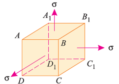
Consider a cube ABCDA1B1C1D1 as shown in fig. Let the cube be subjected to three mutually perpendicular stresses of same intensity.
Here,  = Tensile stresses
 = length of cube
E = Young’s modulus of the cube material.
Now, we will consider deformation of any one particular side (say AB). Here, this deformation will be caused by,
- Tensile stresses on faces BB1CC1 and AA1DD1.
- Compressive stresses on faces AA1BB1 and DD1CC1.
- Compressive stresses on faces ABCD and A1B1C1D1.
The tensile stress mentioned above will result in longitudinal strain of  /E. The compressive stresses will result in lateral strain of [ν*(
 /E)], where ν = Poisson’s ratio.
Thus, the total strain produced is given as,


Now, the volume of cube is  3, thus
 3
3
Differentiating with respect to  , we get,


Now, replacing the value of  mentioned above.


Now, replacing  3 by
3 by  ,
,

Replacing  by
by  , we get,


The above equation gives relation between Young’s Modulus (E), and Bulk Modulus (K).
Relation between Young’s Modulus and Modulus of Rigidity:

Consider a cube of length  subjected to a shear stress of
  , as shown in the above fig.(a). Due to these stresses, diagonal BD will be elongated, and diagonal AC will be shortened, to BD1 and AC1 respectively.
This shear stress will cause shear strain ( , shown in fig.


Now, we found that the linear strain on BD is half of the shear strain and is tensile in nature. Similarly, it can be proved that linear strain on AC is half of shear strain and is compressive in nature.
Now, linear strain in diagonal BD is

Where  = shear stress and C = Modulus of rigidity.
We know that the effect of the shear stresses will be the tensile stress on diagonal BD and compressive stress on diagonal AC. The tensile strain on diagonal BD by tensile stress on diagonal BD is given by,

The tensile strain on diagonal BD by compressive stress on diagonal AC is given by,

The combined effect of the above-mentioned strains is given as,

Therefore, combining the strain obtained and shear strain obtained we get,


The above equation gives relation between Young’s Modulus E and Modulus of Rigidity (C).
Key Takeaway:
Stress-strain diagram for ductile and brittle materials:
Stress-Strain curve for Ductile Materials:
A material is said to be ductile in nature if it elongates appreciably before fracture. One such material is mild steel. The tensile test of mild steel is carried out on a specimen of uniform cross-section throughout its gauge length. The specimen is gripped between two grips (JAWS) of the tensile testing machine, with which gradually increasing load is applied. The load and extension in the gauge length (50 mm) of the specimen are observed. A graph is drawn between load and extension i.e., stress and strain as shown in fig.
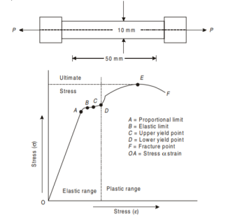
Proportional Limit. From the origin O to the point A, stress-strain diagram is a straight line i.e., stress is proportional to strain. Hook’s law holds good up to this point A. Beyond point A, the stress is no longer proportional to the strain. Hence point A is the proportional limit stage. Thus, the limit up to which stress is directly proportional to strain is called proportional limit.
Elastic Limit. Point B indicates the elastic limit stage. Between points A and B although the strain increases slightly more than the stress, yet the material is elastic i.e., on the removal of load, the material will regain its original shape and size. If the material is stressed beyond point B, the deformation will take place. Points C and D are upper and lower yield points respectively. Between points B and C, the strain increases more rapidly than the stress. At this point C the dial, which gives the reading of the load suddenly becomes stationary for few seconds to point D. Beyond point D, the load again starts increasing but the elongation increases at faster rate than load up to point E. Hence E indicates maximum or ultimate stress point. The bar of specimen begins to form a local neck. Point F is the breaking point. The extension remains continuous even with lesser load and fracture occurs at point F. The stress corresponding to the peak load is called ultimate tensile stress or ultimate tensile strength or tensile strength. The stress corresponding to the load when the specimen ruptures is called rupture strength.
Yield Point. The yield point is the point at which considerable elongation of the test specimen occurs with no noticeable increase in the tensile load (Stress). This phenomenon is known as yielding of the material and point C is called the yield point. The corresponding stress is known as the yield stress. In this region (i.e., between points C and D) the material becomes perfectly plastic, which means that it deforms without an increase in the applied load. The elongation of specimen in the perfectly plastic region is typically 10 to 15 times the elongation that occurs up to the proportional limit.
Ultimate Stress. The ratio of maximum load to the original cross-sectional area of a bar is called ultimate stress.

Percentage Elongation. The ratio of percentage increase in gauge length to the original gauge length is called the percentage elongation.

Where,
 = original gauge length
 = final gauge length after fracture
Working Stress. The greatest stress that is induced in a section is called the working stress.

Factor of Safety. Factor of Safety can be defined as the ratio of Ultimate stress to the Working or generated stress.

The factor of safety is also known as factor of ignorance. It is decided by experience and depends upon the number of factors such as nature of loading, degree of safety, degree of economy required, permanency of design, material used, etc. For cast iron, concrete, wood etc. the value of factor of safety may be taken as 4 to 6.
Breaking Stress. The ratio of load at the breaking or fracture point and original cross-sectional area of a material is called breaking stress or rupture stress.

Rupture Strength
The rupture strength is the stress at failure. The elongation of the bar beyond ultimate point is accompanied by a decrease in the load and fracture or breaking lastly occurs at a point shown as F. The rupture stress at F is less than the ultimate stress at E (as shown by curve EF) is somewhat misleading. When a test specimen is stretched, lateral contraction occurs. The resulting decrease in cross-sectional area is too small to have a noticeable effect on the calculated values of the stresses up to the yielding region, but beyond that point the reduction in area begins to alter the shape of the curve. When the stress-strain graph approaches ultimate stress, the reduction in cross-sectional area of the specimen is clearly visible and then the necking of the section takes place. If the actual cross-sectional area of the narrowest part of the neck is used to calculate the stress, the true stress-strain curve may be obtained.
Percentage reduction in area. Ratio of the percentage decrease in cross-sectional area to the original cross-sectional area is called the percentage reduction in area after rupture.

Where  = Original cross-sectional area,
  = final cross-sectional area.
Nominal Stress and True Stress. When the initial area of the specimen (based on original diameter or nominal diameter) is used in the calculation, the stress is called the nominal stress (or conventional stress or engineering stress). A more accurate value of the axial stress, called the true stress, can be determined by using the actual area of the bar at the cross-section where failure occurs. True stress is always larger than nominal stress because actual area during rupture is always less than the normal area of the section.
True Strain & Nominal strain. If the initial gauge length is used in the calculation, then the nominal strain is obtained. Since the distance between the gauge marks increases as the tensile load is applied, we can calculate the true strain (or natural strain) at any value of the load by using the actual distance between the gauge marks. In tension true strain is always smaller than the nominal strain. The conventional stress strain curve OABCDEF, which is based upon the original cross-sectional area of the specimen and is easy to determine, provides satisfactory information for use in engineering design.
Stress-Strain Curve for Brittle Materials:
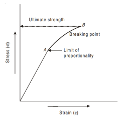
Brittle materials are those which show very little deformation before fracture. Brittle materials like concrete, aluminium and cast iron have very low proportional limit and do not show the yield point. For brittle materials the stress-strain graph is continuous curve from the beginning itself as shown in fig. Below. The breaking stress at point B is well defined. The brittle material has relatively small tensile strain up to the breaking point.
Factor of Safety
Factor of Safety can be defined as the ratio of Ultimate stress to the Working type of stress.

The factor of safety is also known as factor of ignorance. It is decided by experience and depends upon the number of factors such as nature of loading, degree of safety, degree of economy required, permanency of design, material used, etc. For cast iron, concrete, wood etc. the value of factor of safety may be taken as 4 to 6.
Key Takeaway:
Normal Stress (  )
)
External forces acting on a body are transmitted to the supports via the body's material. This phenomenon causes the body to deform and develop equal and opposing internal forces. These tend to resist deformation due to the cohesion of the material's particles. The magnitude of the internal resisting forces is equal to the applied forces, but the direction is reversed.

The resisting force per unit area of the surface is known as stress intensity or simply stress and is denoted by Sigma (σ).
σ = Stress
P = Load
A = Sectional Area

If intensity of stress is not uniformly distributed throughout the body, then stress can be written as,

 = infinitesimal area of cross-section
 = load applied on area
The stress can be tensile or compressive in nature. Stress at elastic limit is known as proof stress.
1 MN/m2 = 1 MPa = 1 X 10^6 N/m2 = 1 N/mm2
1 GPa = 1000 MP a = 1000 N/mm2 = 1 kN/ mm2
Stress induced due to forces which are acting normal to the cross-sectional area of the section or beam is called Normal stress.
Normal Stresses are further classified as Tensile and Compressive Stresses.
- Tensile Stress: When a section is subjected to two equal and opposite pulls due to which body tends to increase in length as shown in fig., the stresses induced are called Tensile Stresses. As a result of the tensile stress, the cross-sectional area of the section decreases.

- Compressive Stress: When a section is subjected to two equal and opposite pushes due to which body tends to decrease in length as shown in fig., the stresses induced are called Compressive Stresses. As a result of the compressive stress, the cross-sectional area of the section increases.

Normal Strain ( )
)
Normal strain is denoted by the Greek letter epsilon  and occurs when an object elongates in response to a normal stress (i.e., perpendicular to a surface). A positive value indicates tensile strain, while a negative value indicates compressive strain.
Deformation of a body under a load is proportional to its length. The elongation per unit length is known as longitudinal or simple strain.
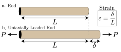

i.e., Strain is deformation  per unit length L.
As it is a ratio of similar quantities, it is dimensionless quantity.
Strain induced due to forces which are acting normal to the cross-sectional area of the section or beam is called Normal strain.
Shear stress (  )
)
When two equal and opposite parallel forces acting on two parts of a body that are not in the same line, one part tends to slide over or shear from the other across any section, and the stress developed is known as shear stress.
If P is the force applied and A is the area being sheared, then the intensity of shear stress is given by,

Keep in mind that shear stress is always tangential to the area it acts on.

Shear strain ( )
)
Shear stresses distort a rectangular element of a body. If the lower surface is assumed to be fixed, the upper surface slides relative to the lower surface, changing the comer angles by angle  . Shear strain is dimensionless and defined as the change in the right angle of the element measured in radians.
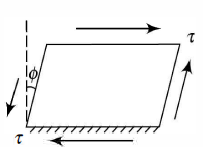
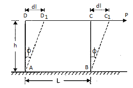

Elasticity & Elastic limit
When an external force acts on a body, the body tends to undergo some deformation. If the external force is removed the comes body back tends to its to origin shape and size, the body is known as elastic body. This property is elasticity.
Hooks law
Robert Hooke was the first person to investigate scientifically, the elastic properties of material and tested using diverse materials like wood, metal, stone, bones etc. He found out that the lengthening of wires was in some sort of proportions to that of the weights applied and stated as “When a material is loaded, within its elastic limit, the stress is proportional to the strain”. Mathematically represented as,

It should be noted that Hooke’s law holds good for tensile as well as compressive loads. E given here is known as Modulus of Elasticity or Young’s Modulus.
Modulus of Elasticity
We know that by using Hooke’s law i.e.
Stress  Strain

This constant of proportionality (E) is known as Modulus of Elasticity or Young’s Modulus. Numerically, Modulus of Elasticity is that value of tensile stress, which when applied to uniform bar will increase its length by unit value of strain. As the strain is dimensionless, the units of Young’s Modulus are same as that of Stress, i.e., Pascal (Pa) or N/m2. This Young’s Modulus is also the slope of stress-strain curve in elastic region that will be discussed later.
Some of the values of E are, Steel = 200-220 GPa, Wrought Iron = 190-200 GPa, Aluminium = 60-80 GPa.
Longitudinal Strain
The ratio of axial deformation to original length of the body is longitudinal or linear strain.

Lateral Strain


Poisson’s Ratio:
When a particular bar is loaded by tensile force, the axial lengthening is accompanied with lateral type of contraction (i.e., contraction which is normal to the direction of the applied load). The lateral strain which is induced at any point in a bar is always proportional to the axial strain at the same point if the material of component is linearly elastic. The ratio of these strains is a property of the material known as Poisson’s ratio. This dimensionless ratio, usually denoted by the Greek letter ν (nu), can be expressed by the equation

Here negative sign indicates opposite directions or signs for strains. ν is assumed same in Tension as well as Compression. Some values of ν are 0.1 for concrete, 0.5 for rubber and approx. 0 for cork.
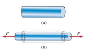
Here fig.(a) represents bar before applying force P, fig.(b) represents bar after loading (Here Lateral strain is denoted by dotted lines).
Key Takeaway:
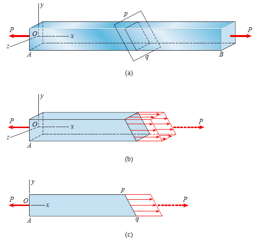
The free-body diagram is obtained by cutting the bar at an intermediate cross section with a plane mn (perpendicular to the x axis). The normal stresses acting over the cut section may be calculated from the formula provided that the stress distribution is uniform over the entire cross-sectional area A.

The material is homogeneous because the bar is prismatic, the axial force P acts at the centroid of the cross-sectional area, and the cross section is away from any localised stress concentrations. Because the cut section is perpendicular to the longitudinal axis of the bar, there are no shear stresses acting on it.
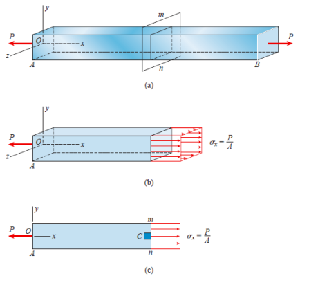
The most useful way to represent the stresses in the bar is to isolate a small material element, such as the element labelled C, and then show the stresses acting on all faces of this element.
This type of element is known as a stress element. The stress element at point C is a small rectangular block (whether a cube or a rectangular parallelepiped) with its right-hand face in cross section mn.
A stress element's dimensions are assumed to be infinitesimally small, but for clarity, we draw the element on a large scale.
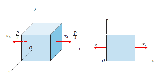
In this case, the edges of the element are parallel to the x, y, and z axes,
And the only stresses are the normal stresses  x acting on the x faces
(Recall that the x faces have their normal parallel to the x axis). Because it
Is more convenient, we usually draw a two-dimensional view of the element instead of a three-dimensional view.

Associated with the forces N and V are normal and shear stresses that are uniformly distributed over the inclined section.
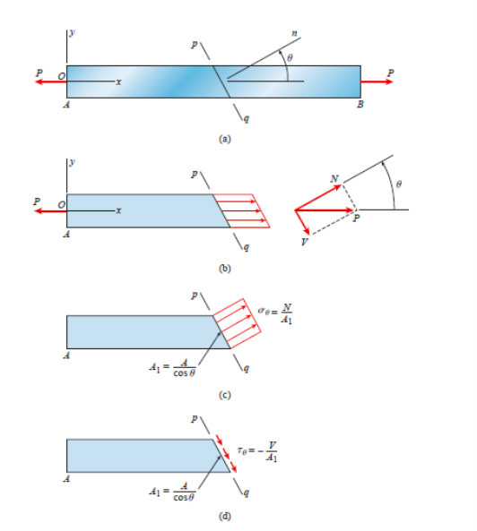


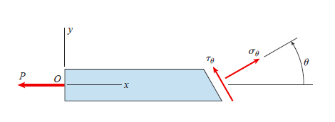


As,

Using, trigonometric relations,


Normal and shear stresses equations below are derived from statics, and therefore they are independent of the material. Thus, these equations are valid for any material, whether it behaves linearly or nonlinearly, elastically or inelastically


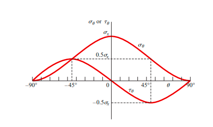
Graph of normal stress & shear stress versus angle of inclined section
Maximum Normal and Shear Stresses,
The horizontal axis gives the angle  which varies from -90 to + 90.
Vertical axis gives  &
& 
 is Measured counter-clockwise from x- axis and a negative angle is measured clockwise.

Then, as  increases or decreases, the normal stress diminishes until at
  becomes 0. Because there are no normal stresses on sections cut parallel to the longitudinal axis. The maximum normal stress occurs at
  and is

At  the normal stress is one-half the maximum value
 on cross sections of the bar (
  = 0) as well as on longitudinal sections
Between these extreme maximum shear stress has magnitude of,

But they tend to rotate the element in opposite directions.
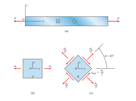
Key Takeaway:
Energy is absorbed in the body whenever a body is strained. Strain energy is the energy absorbed in the body as a result of the straining effect. The straining effect could be caused by a slowly applied load, a suddenly applied load, or a load with impact. As a result, when the load is applied gradually, suddenly, or with an impact, the strain energy is stored in the body. The strain energy stored in the body is equal to the work done in stretching the body by the applied load.
Resilience:
Resilience is defined as the total strain energy stored in a body. When the straining force is removed from the strained body, the body becomes capable of performing work. As a result, resi1ience is also defined as a strained body's capacity to do work after the straining force is removed.
Proof Resilience:
Proof resilience is the maximum strain energy stored in a body. When the body is stressed to its elastic limit, the strain energy stored in it is at its peak. As a result, proof resilience is defined as the amount of strain energy stored in a body when strained up to its elastic limit.
Modulus of Resilience:
It is defined as a material's proof resilience per unit volume. It is an important material property.

Expression for Gradually applied Load:
When an elastic body is subjected to a gradual or static load, the body is strained and work is done on the body, which is stored within the body as internal energy. The strain energy is the work done by the load in straining the body. Because the elongation of most elastic materials increases linearly with increasing load, the load-elongation diagram is a straight line within elastic limits. At any instant, the work done in straining a material is equal to the area under the diagram.
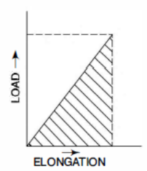
Let P be the gradual load applied to a bar of length L
A is cross-sectional area.
Let  be the total elongation under the load.
V = volume of body
E = Youngs Modulus
Strain Energy = U
Stress induced in body = 
Extension of bar = x
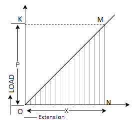
Work done by the load = Area of load extension curve
= Area of Triangle ONM

But Load P = Stress * Area = 
Extension, x = strain * length


Work done by the load in stretching is equal to strain energy stored in the body.

Proof Resilience is calculated when the stress is taken at elastic limit,

Modulus of Resilience is Strain energy per unit volume

Expression for Suddenly applied Load:
When the load is applied suddenly to a body, the load is constant throughout the process of deformation of the body.
Let P be the sudden load applied to a bar of length L
A is cross-sectional area.
Let  be the total elongation under the load.
V = volume of body
E = Youngs Modulus
Strain Energy = U
Stress induced in body = 
Extension of bar = x
Work done by the load = Load * Extension


Equating strain energy to work done,


Key Takeaway:
The load dropped from a certain height before the load commences to stretch the bar is a case of a load applied with impact. Consider a vertical rod fixed at the upper end and having a collar at the lower end as shown below,
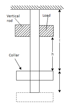
P = Load dropped
L = Length of the rod,
A = Cross-sectional area of the rod,
V = Volume of rod = A x L,
h = Height through which load is dropped
 L = Extension of the rod due to load P
E = Modulus of elasticity of the material of rod
 = Stress induced in the rod due to impact load
Strain in the bar,


Work done by load = Load * Distance moved

Strain energy stored by the rod,


Equating Work done to strain energy


Multiplying by  on both sides,


The above is a quadratic equation in 
So,

Solving,

Key Takeaway:

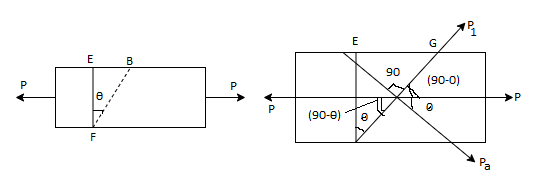
Consider a Rectangular member of uniform cross-sectional area A and of unit thickness.
Let,
P = Axial force acting on -the member.
A = Area of cross-section, which is perpendicular to the line of action of the force P.
Stress along x – axis,

Hence, the member is subjected to a stress along x-axis. Consider a cross-section EF which is perpendicular to the line of action of the force P.
Area of section EF = EF *1 = A
Stress on section 
Area of section FG = FG *1

Stress on section 
This stress, on the section FG, is parallel to the axis of the member (i.e., this stress is along x-axis). This stress may be resolved in two components. One component will be normal to the section FG whereas the second component will be along the section.PG (i.e., tangential to the section FG). The normal stress and tangential stress (i.e., shear stress) on the section FG are obtained.
 The component of the force P, normal to section FG =
 = The component of force P, along the surface of the section FG (or tangential to the surface FG) =
 = Normal stress across the section FG
 = Tangential stress (i.e., shear stress) across the section FG.
Normal stress and tangential stress across the section FG are obtained as,

As, ( 


It is seen that the normal stress ( ) on the section fb will be maximum, when
  or
or  is maximum. And
  will be maximum when
  = 0° as
Cos 0° = 1. But when  = 0°, the section fg will coincide with section EF. But the section EF is normal to the line of action of the loading. This means the plane normal to the axis of loading will carry the maximum normal stress.
Maximum normal stress = 
It is, observed that the tangential stress (i.e., shear stress) across the Section FG will be maximum when sin 2  is maximum. And sin 2
  will be maximum when sin 2
  = 1 or 2
 = 90 or 270°

Max. Value of shear stress = 
Key Takeaway:
Principal planes and principal stresses:
The planes with no shear stress are referred to as principal planes. As a result, principal planes are planes with zero shear stress. These planes are only subjected to normal stresses. Principal stresses are normal stresses that act on a principal plane.
Or it can be defined as,
In general, a body can be acted on by both direct and shear stresses. However, even in such complex loading systems, three mutually perpendicular planes exist, on each of which the resultant stress is completely normal. These are referred to as principal planes, and the normal stress across these planes is referred to as principal stresses.
Largest is Major principal stress  & smaller one is Minor principal stress
  .
.
Major and minor principal planes are the names given to the corresponding planes. The third principal stress is assumed to be zero in two-dimensional problems.
In previous units, we have studied direct tensile and compressive stresses as well as shear stress. But we have considered only one type of stress at a single time acting in only one direction. But mostly in practical examples the complex stresses are exerted on a body, consisting of direct stresses like tensile and compressive stresses and shear stresses from different directions. These stresses are called as compound stresses.
Transformation of Plane Stress
Consider a general plane stress in x-y co-ordinate system. We now want to transform this to another stress system in, say, x′- y′ co-ordinates, inclined at an angle θ from the side. This is shown in figure.
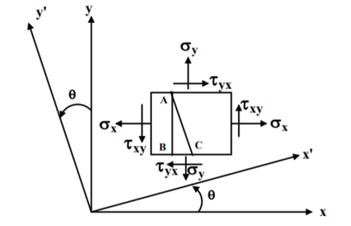
A two-dimensional stress acting on the faces of a cubic element is shown in fig. In plane stress assumptions, the non-zero stresses are σx, σy and τxy=τyx. We may now isolate an element ABC such that the plane AC is inclined at an angle θ and the stresses on the inclined face are σ′x and τ′xy.
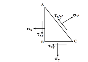
Location of the plane stress in this transformation is given by
Location of principal plane

This is the formula which relates the angle θ with the stresses acting on the body.
Sign Conventions in Analytical Method
- All Tensile stresses and strains are taken as positive, while all compressive stresses and strains are taken as negative.
- Shear stress which tends to rotate the element in clockwise direction is taken as +ve, while the one which rotates in anticlockwise direction is taken as negative.
This sign conventions are followed throughout the entire course for the compound stresses and strains without any changes
Stresses on oblique section of body subjected to a direct stress in one plane
Assume a rectangular body with uniform cross-sectional area of unit thickness subjected to direct tensile stress in X-X axis. Now, consider an oblique section AB inclined with the axis X-X.
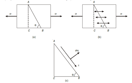
Let, σ = tensile stress across the face AC,
θ= angle, which AB makes with BC i.e., with the X-X axis
We know that horizontal force acting on the face AC is 
Resolving the force perpendicular to the section AB,
 ...(i)
Now resolving the force tangential to section AB
 ...(ii)
We know that normal stress across the section AB,
 …(iii)
 =
= 
Shear stress acting, 
Resultant stress is given by,

Stresses on an oblique section of a body subjected to direct stresses in two mutually perpendicular directions
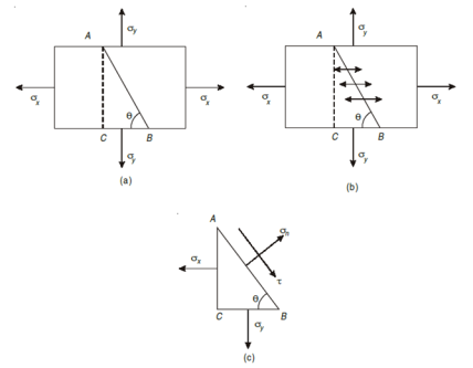
 = Tensile stress along x – x axis
 = Tensile stress along y – y axis
θ = Angle which the oblique section AB makes with x – x axis in clockwise direction.
Normal stress across the section AB,

Shear stress (tangential stress) across AB,

 max =
max = 
When 2θ = 1 or 2θ = 90 or 45,
Resultant stress is given as,

Stresses due to combined normal and shear stresses
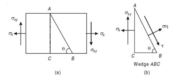
Consider a rectangular body of a uniform cross-sectional area and unit thickness subjected to a direct tensile stress along x – x axis accompanied by a positive (i.e., clockwise) shear stress along X-X axis
Let,
σx = Tensile stress in x – x direction.
τxy = Positive (i.e., clockwise) shear stress along x – x axis
θ = Angle which oblique section AB makes with x – x axis in clockwise direction.
Normal stress is given by,
 +
+
Tangential stress is given by,
 -
- 
Resultant stress is given by,
 t
t
Major principal stress is given by,

Minor principal stress is given by,

Location of principal plane

Maximum shear stress,

= ±
Major principal strain 
Minor principal strain 
Key Takeaway:


 +
+
 -
- 

Graphical method for the stresses on an oblique section of a body
By drawing a Mohr’s circle, the normal, shear and resultant stresses may be determined graphically.
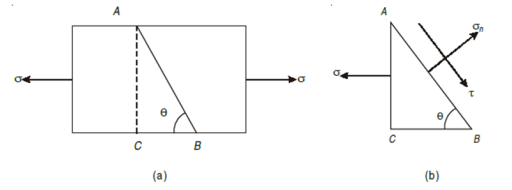
Consider a rectangular body of uniform cross-sectional area and unit thickness subjected to a direct tensile stress along x – x axis as shown in Fig. 2.6 (a, b). Now consider an oblique section AB inclined with x – x axis, on which we are required to find out the stresses as shown in Fig.
σ = Tensile stress, in x – x direction
θ = Angle which the oblique section AB makes with the x – x axis in clockwise direction
Steps to draw Mohr’s Circle are given below:
- Draw a horizontal line X – X and take a suitable point O on it.
- Cut off OJ equal to tensile stress (σ) to some suitable scale towards right (because σ is tensile). Bisect OJ at C. Now point O represents the stress system on plane BC and the point J represents stress system on plane AC.
- Now with C as centre and radius equal to CO or CJ draw a circle. It is known as Mohr’s circle for stresses.
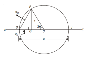
- Now through C draw a line CP making an angle of 2θ with CO meeting the circle at P. The point P represents the section AB.
- Through P, draw PQ perpendicular to OX. Join OP. Now OQ, QP and OP will give normal stress, shear stress and resultant stress and the angle POJ is called the angle of obliquity (θ).
Mohr’s circle for stresses on an oblique section of a body subjected to direct stresses in one plane accompanied by a simple shear stress
Consider a rectangular body of a uniform cross-sectional area and unit thickness subjected to a direct tensile stress along x – x axis accompanied by a positive (i.e., clockwise) shear stress along x – x axis
σx = Tensile stress in x – x direction.
τxy = Positive (i.e., clockwise) shear stress along x – x axis, and
θ = Angle which oblique section AB makes with x – x axis in clockwise
Direction.
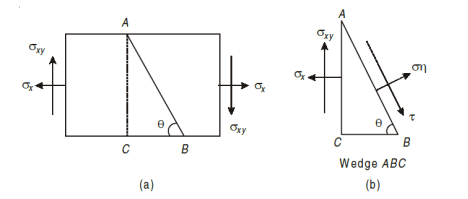
First, consider the equilibrium of the wedge ABC. We know that as per principle of simple shear the face BC of the wedge will also be subjected to an anticlockwise shear stress. Now draw the Mohr’s circle of stresses as shown in Fig
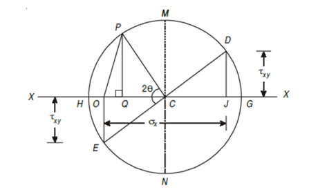
- First of all, take some suitable point O and through it draw a horizontal line XOX.
- Cut off OJ equal to tensile stress σx to some suitable scale and towards right (As σx is tensile + ve).
- Now erect perpendicular at J along the line X – X (because τxy is positive along X – X axis) and cut off JD equal to the shear stress τxy to the scale. The point D represents the stress system on plane AC. Similarly, erect a perpendicular below the line X – X (because τxy is –ve along Y – Y axis) and cut off OE equal to shear stress τxy to the scale. The point E represents the stress system on plane BC. Join DE and bisect it at C.
- Now C as centre and radius equal to CD or CE draw a circle. It is known as Mohr’s circle of stresses.
- Now through C, draw a line CP making an angle 2θ with CE in clockwise direction meeting, the circle at P. The point P represents the stress system on the section AB.
- Through P, draw PQ perpendicular to the line OX. Join OP.
- Now OQ, QP and OP will give the normal, shear and resultant stresses to the scale. And the angle POC is called the angle of obliquity.
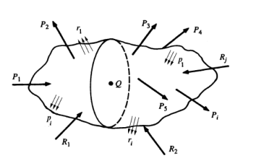
Consider the following general solid body loaded: Pi and pi represent applied concentrated forces and surface force distributions, respectively, while Ri and ri represent possible support reaction force and surface force distributions, respectively.
To determine the state of stress at point Q in the body, a surface containing the point Q must be exposed. This is accomplished by cutting a planar slice through the body and intersecting the point Q. This slice's orientation is arbitrary, but it is usually made in a convenient plane where the state of stress can be easily determined or where certain geometric relations can be used.
Structural Member
The first slice shown is oriented arbitrarily by the surface normal x. This creates the yz plane. The external forces acting on the remaining body are depicted, as well as the distribution of internal forces (stress) across the exposed internal surface containing Q. In general, this distribution will be neither normal nor tangential to the surface at Q and will not be uniform along the surface. The force distribution at Q, on the other hand, will have components in both the normal and tangential directions. Tensile or compressive stresses, as well as shear stresses, will be involved.
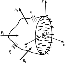
Isolated section
Consider an infinitesimal area  surrounding Q The equivalent concentrated force due to the force distribution across this area is
  , which in general is neither normal nor tangential to the surface. (The subscript x is used to designate the normal to the area). The force
  has components in the x, y, and z directions, which are labelled,
  respectively. Note that the first subscript denotes the direction normal to the surface and the second gives the actual direction of the force component. The average distributed force per unit area (average stress) in the x direction is,

Recalling that stress is a point function, we obtain the exact stress in the x direction at point Q by allowing  to approach zero.
Thus,


Stresses arise from the tangential forces  and
and  as well, and since these forces are tangential, the stresses are shear stresses.
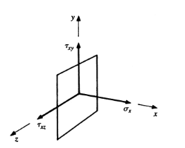
Stress components
The shear stresses  and
and  are the components of the net shear stress acting on the surface, where the net shear stress is given by,

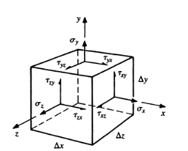
Stress on orthogonal surface

For extremely rare cases, it can be shown that adjacent shear stresses are equal, and the stress matrix is symmetric and written as,

1D Stress system
The relationship between Stress & strain for unidirectional Stress (Normal stress in one direction only) is given by hooks law.
For a material loaded within its elastic limit normal stress produced is proportional to strain produced.


2D Stress system
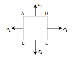
Normal stress in x-direction = 
Normal stress in y-direction = 
Strain is produced by  in x & y direction.
Longitudinal strain in x direction = 
Lateral strain in y direction = 
Strain is produced by  in y & x direction.
Longitudinal strain in y direction = 
Lateral strain in x direction = 
 = Total strain in x direction
 = Total strain in x direction
Total strain in x direction = 
Total strain in y direction = 
3D Stress system
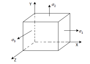
Normal stress in x-direction = 
Normal stress in y-direction = 
Normal stress in z-direction = 
Strain in x direction due to  =
= 
Strain in y direction due to  =
= 
Strain in z direction due to  =
= 
Strain in x direction due to  =
= 
Strain in y direction due to  =
= 
Strain in z direction due to  =
= 
Strain in x direction due to  =
= 
Strain in y direction due to  =
= 
Strain in z direction due to  =
= 
 = Total strain in x direction
 = Total strain in y direction
 = Total strain in z direction
Total strain in x direction = 
Total strain in y direction = 
Total strain in z direction = 
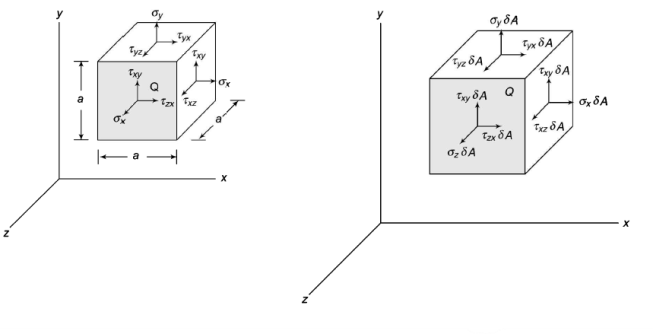
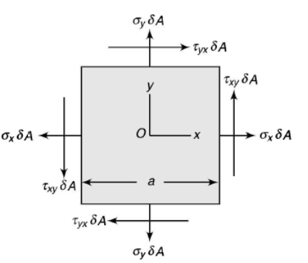
Consider a small cube with side a and a centre at Q to visualise the stress condition at a point Q within a body. The stresses act on each of the cube's six faces. The normal and shear stresses are depicted. The normal and shear forces acting on the cube's different faces are calculated by multiplying the stress component by the surface area of the corresponding face. Equal and opposing forces to those depicted in the figure act on the cube's hidden faces. When a xy plane projection is used, it is clear that the moments about the z-axis with non-zero values are shear forces.

Or

Which indicates that the y component of the shear stress on a face perpendicular to the x-axis is equal to x component of the shear stress on a face perpendicular to the y-axis.
Similarly, it can be shown that,


In order to determine the stress components on a plane of arbitrary orientation, consider a tetrahedron. t has three of its faces parallel to the coordinate planes whereas the fourth face ABC is perpendicular to the line QN. In the figure, the face QAB is shown parallel to yOz plane or the plane perpendicular to x-axis. Similarly, QBC is parallel to xOy and the plane QCA parallel to plane xOz.
Let lx, ly and lz be the direction cosines of the line QN with respect to x-, y- and z-directions. Then if  is the area of the face ABC, areas of the faces perpendicular to the x-, y- and z-axis will be
  · lx,
· lx,  · lY and
  · lz respectively.
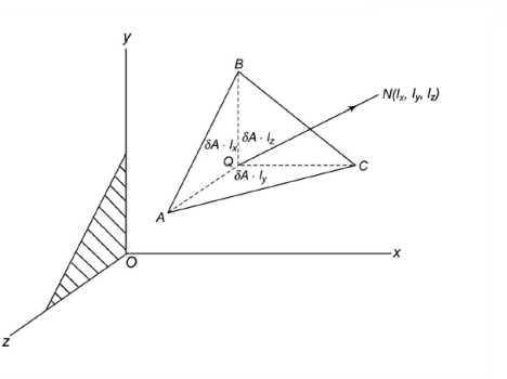
The state of stress at point Q be defined by the stress components 
The forces exerted on the faces are obtained by multiplying each stress component by the corresponding area of that face.
On the face ABC, the normal force will be of magnitude  along QN and a shear force of magnitude
  perpendicular to QN but of unknown direction on the face ABC.
Now, for equilibrium of the tetrahedron, the sum of components of all the forces along QN must be zero

Normal force on face QAB = 
Component of this force along QN = Normal force on face QAB * lx
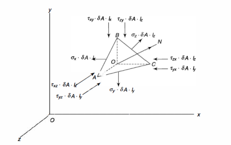
Similarly for others can be determined.
Therefore, 
Dividing trough 


Let shear force of magnitude r · 5A acts along QS perpendicular to QN. Let lsx, lsy and lsz be the direction cosines of the line QS with respect to x, y and z-directions. As normal-stress direction and the shear-stress direction are at right angles to each other, the following equation must be satisfied,

Then


Principal Stresses are given as,

Key Takeaway:


- Total strain in x direction =

- Total strain in y direction =

- Total strain in z direction =


Concept of Equilibrium:
The term "equilibrium" is used to describe a body that is either stationary or moving at a constant velocity. Only balanced forces and balanced couples can act on a body in this state. It is not being acted on by an unbalanced force or an unbalanced couple. The concept of equilibrium is commonly used in statics to analyse a body that is stationary or is said to be in a state of static equilibrium.
Particle:
A particle is a body whose size has no effect on the results of mechanical analyses performed on it, and thus its dimensions can be ignored. A particle is very small in comparison to the size of the system being studied.
Body:
A body is made up of a collection of particles. The size of a body influences the outcome of any mechanical analysis performed on it. When the relative positions of a body's particles are always fixed and do not change when the body is acted upon by any load, the body is said to be rigid (whether a force or a couple).
Most bodies encountered in engineering work can be considered rigid from the standpoint of mechanical analysis because the deformations that occur within these bodies as a result of load action can be ignored when compared to other effects produced by the loads.
Effects of the action of forces on particles and rigid bodies:
In general, a force acting on a particle causes the particle to move. A force acting on a body not only causes it to translate (as in the case of the particle), but it also causes it to rotate about any axis that does not intersect or is not parallel to the force's line of action. The rotational tendency is referred to as the "moment."
Free body:
In general, mechanical analysis of a structure begins by applying Newton's law to the entire structure or a portion of the structure. To see what happens to a specific part of a structure, that part must be isolated from the rest of the body. Isolating the part that is the subject of analysis is a critical concept in mechanical analysis. A free body is a part that has been isolated.
Mechanical System:
A mechanical system is a body system that can be separated from other bodies. A single body, a portion of a body, or a group of connected bodies can make up the system. The bodies that comprise the system can be rigid or non-rigid. A mechanical system can be solid, fluid, or a combination of the two.
A mechanical system is isolated by cutting and isolating the system from its surroundings. We can see the interactions between the isolated part and the other parts because it is isolated. A free body is formed by the part that has been cut (imaginarily). The free-body diagram (FBD) of the isolated part is a diagram that depicts the free body, complete with the system of external forces acting on it as a result of its interaction with the parts that have been removed.
Free-body Diagram (FBD):
The FBD of a body system depicts all loads acting on the isolated body's external boundary. Loads include active forces applied to the free body by the parts that have been removed from it. It is worth noting that when the internal forces acting on a structure are exposed by the imaginary "cutting" process used to form the free body, they become external forces.
Equilibrium equations for a rigid body:
Any applied load will cause a rigid to translate and rotate about a specific axis. The tendency to translate is caused by the resultant force acting on the body, and the tendency to rotate is caused by the resultant couple acting on the body. If the resultant force and resultant couple are both zero, the body will be in equilibrium.
Mathematically, equilibrium is determined by the conditions:
∑F =0 & ∑M =0
Equilibrium in 2D:
The resultant force vector for a planar force system acts on the original force system's pane of action. The moment vector that results act perpendicular to that plane. As a result, the resulting force vector is represented by two perpendicular components acting on the plane. The resultant moment vector, on the other hand, can be represented by a circular arrow indicating its sense of action.
∑F = ∑Fx + ∑Fy
∑MO = ∑|r × F| = ∑Fd
Where d is the perpendicular distance between any moment centre O and the line of action of F.
The second expression in this equation gives the magnitude of the resultant moment. The direction of the ∑MO vector is perpendicular to this page; its sense of action is indicated by the circular arrow which acts in the clockwise or anti-clockwise direction, depending on the sense of r and F.
The equilibrium equation for the two-dimensional case can be written in the scalar form as,
∑Fx = 0
∑Fy = 0
∑Mo = 0
The first two equations in Equation state that the sum of the force components in the x- and y- directions is zero. The moment about any point O is zero, according to the third expression.
All three expressions of Equation are necessary for equilibrium. Note that only three independent equations exist to describe equilibrium in a plane. Hence, only three unknown values can be solved.
Alternative Equations:
Fx = 0 or Fy = 0
MA = 0
MB = 0
(Or)
∑MA = 0
∑MB = 0
∑MC = 0
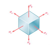
Under the given multiaxial loading, the element will deform into a rectangular parallelepiped of sides equal to,

The element under consideration could also undergo a translation, but we are concerned here only with the actual deformation of the element, and not with any possible superimposed rigid-body displacement.
Using, principle of superimposition strain components can be represented into stress components. This principle states that the effect of a given combined loading on a structure can be obtained by determining separately the effects of the various loads and combining the results obtained, provided that the following conditions are satisfied:
- Each effect is linearly related to the load that produces it.
- The deformation resulting from any given load is small and does not affect the conditions of application of the other loads.
Total strain in x direction = 
Total strain in y direction = 
Total strain in z direction = 
The results obtained are valid only if the stresses do not exceed the proportional limit, and as long as the deformations involved remain small. We also recall that a positive value for a stress component signifies tension, and a negative value compression. Similarly, a positive value for a strain component indicates expansion in the corresponding direction, and a negative value contraction.
Key Takeaway:
- Total strain in x direction =

- Total strain in y direction =

- Total strain in z direction =

In tensile test, yield point load can be easily determined but in most of machine elements subjected to complex stresses, it is very difficult to know the point of yielding.
To improve design of machine elements, various theories of failures are developed based on physical behaviour of material.
Various theories of failure
- ‘Maximum Principal Stress theory’ also called Rankine Theory used for brittle materials
- ‘Maximum Shear Stress theory’ also called Coulomb, Tresca and Guest’s theory used for ductile materials
- ‘Maximum Principal Strain theory’ also called St Venant’s theory
- ‘Maximum Strain Energy theory’ also called Haigh’s theory good for ductile materials
- ‘Shear Strain Energy theory OR Distortion Energy theory’ also called Huber von Mises and Hencky’s theory
Maximum Principal Stress Theory
According to this theory maximum principal stress induced in material under complex load condition exceeds the maximum normal strain in simple test, the material fails.
Failure condition, 
 = yield point stress

This theory is not suitable to design machine elements as  and
and  are in opposite direction.
Maximum Shear Stress Theory
According to this theory when maximum shear strength in actual case exceeds maximum allowable shear stress in tension test then material fails.


This theory is widely used in the analytical way to calculate for the ductile materials. This has proved to be widely used theory for simple calculations in designing of simple machine elements.
Maximum Principal Strain Theory
It states that when normal strain in actual case is more than maximum normal strain, strain occurred in simple tension test, material fails. This theory deals with the strain energy in the distorted material.

Maximum Strain Energy Theory
The energy stored in the material when the material is said to be deformed is called as strain energy. According to this theory when total strain energy exceeds the total strain energy in simple tensile test then material fails.
The condition is given by,

This condition gives the limiting condition of the strain energy in the material or else the material will fail.
Distortion Energy Theory
The distortion energy is also known as deviatoric energy it is the shear stress energy in the material. When maximum shear strain energy in actual case is more than maximum shear strain in simple tension test, material fails. This theory is highly recommended but used rarely due to difficult calculations.
The condition for limiting value is,

This is the maximum distortion energy in the material after this limit the material fails.
Key Takeaway:
When the temperature of a body is raised or lowered, there is corresponding increase or decrease in its dimensions and if this change in dimensions due to the temperature variation is prevented by application of external forces, the body develops stress in it, which is called the temperature stress; and the corresponding strain is called the temperature strain. The extension due to rise of temperature, can be checked or suppressed by compressive forces; thereby producing compressive stresses in the body or vice versa. Suppose a bar of uniform section and of length l is heated through temperature T. The length of the bar will increases depending upon its co-efficient of linear expansion which is defined as the increase in length per unit rise of temperature per unit original length and is generally denoted by the Greek letter  (alpha).
Extension of the bar when free to expand = αTl.
Now suppose, this extension due to increase of temperature is prevented by either fixing the bar at its ends or by the application of external compressive forces.


Which is compressive in nature.
Temperature stress = Temperature strain × E = αTE (compressive)
Conversely, the contraction caused by lowering of the temperature can be checked by applying tensile forces to the bar resulting in temperature stress of tensile nature in it.
Temperature Stress in Composite Members
Consider a composite bar comprising of two metals (1) and (2), as show in Fig. Suppose x–x be the initial level and y–y be the final level after the rise in temperature t. If both bars were free to expand, the extension of material (1) would be lα1t and that of material (2) would be lα2t on the assumption (α2 > α1). Since both materials are rigidly connected at the ends, material (1) is forced to extend a distance x´1 and material (2) is forced to compress a distance x´2 as shown in figure. Stresses in materials will be induced only due to these forced changes x´1 and x´2.
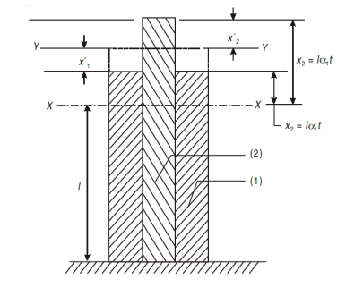
From the figure it will be seen that:


Also, since no external force is applied to the composite bar,
Tensile force in material (1) = Compressive force in material (2)
Thus, using the above equations, the desired values can be determined.
In addition to rise in temperature t, if the bar is subjected to an external load P (Fig. Below) material (2) will suffer further compression and exerts an additional upward reaction P2, whereas material (1) will be relieved of its forced extension x´1 and help P in downward by force P1.
For equilibrium P + P1 = P2
α1 α1 – α2α2 = P
From the above equations, value of α1 and α2 can be found out.
Key Takeaway:
- Extension of the bar when free to expand = αTl.
- Temperature stress = Temperature strain × E = αTE

References:
- Strength of Materials – S.S Rattan (2nd Edition Tata McGraw Hill)
- Mechanics of Materials – Ferdinand P. Beer, E. Russell Johnston (6th Edition McGraw Hill)
- Mechanics of Materials – James M. Gere, Barry J. Goodno (Brief Edition CENGAGE Learning)
- Mechanics and Strength of Materials - Vitor Dias da Silva (1st edition Springer)
- Elements of strength of materials by Timoshenko (2nd Edition)
- Mechanics of Materials (Gere & Timoshenko 2nd edition)
- Strength of Materials (Timoshenko Volume I & II)
- Strength of Materials by Timoshenko and Young, (East West Press)


