Unit - 2
Stresses in Beams, Deflection of beams and Torsion
When an external load acts on a beam, shear force and bending moments are created at all points along the beam. The beam deforms because of the shear force and bending moment. The beam's material will provide resistance or stresses against these deformations. These stresses can be calculated under certain conditions. Bending stresses are the stresses introduced by a bending moment.
When a length of a beam is subjected to a constant bending moment and no shear force (i.e., zero shear force), the stresses are set up in that length of the beam due to B.M. Only, and that length of the beam is said to be in pure bending or simple bending. Bending stresses are the stresses that form along the length of the beam.
Assumptions:
- The material is homogeneous and isotropic,
- Transverse planes remain plane and perpendicular to the neutral surface after bending
- Initially, the beam is straight, and all longitudinal filaments are bent into circular arcs with a common centre of curvature which is large compared to the dimensions of the cross-section.
- The beam is symmetrical about a vertical longitudinal plane passing through vertical axis of symmetry for horizontal beams.
- The stress is purely longitudinal and the stress concentration effects near the concentrated loads are neglected.
Theory of Simple Bending:
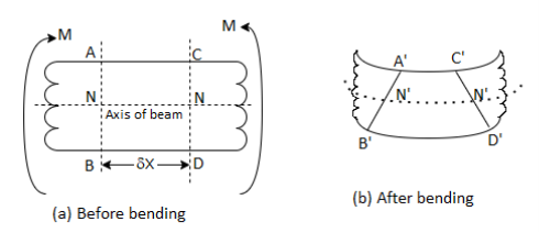
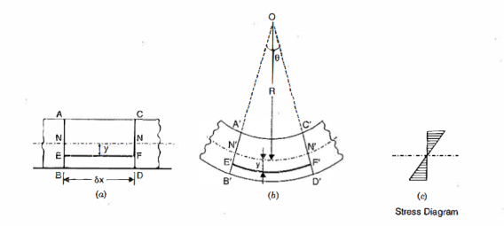
Simple bending is applied to a beam. Consider a small length  of this section of the beam. Consider two sections AB and CD that are normal to the beam's axis N-N. The part of length
  will be deformed because of the bending moment's action. All the beam's layers, which were originally the same length, are no longer the same length.
The top layer, for example, AC, has deformed to the shape  .This layer's length has been reduced. The bottom layer BD has deformed to form the shape B'D." This layer has grown in length.
Some layers have been shortened, while others have been elongated. There will be a layer between the top and bottom of the beam that is neither shortened nor elongated. This layer is referred to as the neutral layer or the neutral surface
The layers above and below N - N (or N' - N') have been shortened and elongated, respectively. Compressive stresses will be applied to the layers above N - N due to the decrease in lengths. Tensile stresses will be applied to the layers below N -N as the lengths of these layers increase.
We can also see that the top layer has been shortened to the greatest extent possible. The length of the layers decreases as we progress towards layer N - N. There is no change in length at layer N - N. This means that the compressive stress will be greatest in the top layer.
Similarly, the length increase will be greatest at the bottom layer. The length of the layers decreases as we progress from the bottom layer to layer N -N. As a result, the amount by which a layer increases or decreases in length is determined by the layer's position with respect to N-N. This bending theory is known as the theory of simple bending.
Example:
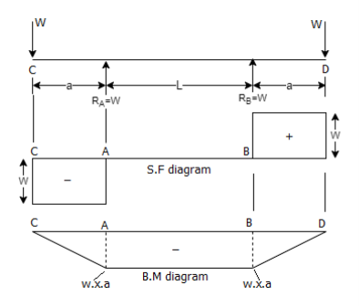
A beam that is simply supported at A and B and overhangs by the same length at both supports. At each end of the overhanging portion, a point load was applied. From these diagrams i.e., the SF and BM Diagrams for the beam are seen clearly; there is no shear force between A and B, but the B.M. Between A and B is constant. This means that the beam is only subjected to a constant bending moment between A and B. This state of the beam between A and B is referred to as pure bending or simple bending.
Expression for Bending stress
Consider a portion of pure beam subjected to pure bending.
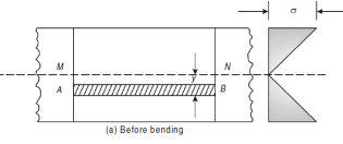
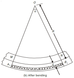
A fibre such as AB at a distance y from the neutral axis as shown in Fig. (b) is chosen. After bending it has elongated and is shown by A1B1 (Fig. b). Let R be the radius of the neutral surface after bending making an angle θ at the point O.
MN = R θ
A1B1 = (R + y) θ


Stress intensity in any form is proportional to the distance of the fibre from the neural axis.
Stress variation


Since E and R are constant, therefore stress in any layer is directly proportional to the distance of the layer from the neutral layer. The equation shows the variation of stress along the depth of the beam. The variation of stress is linear.
All layers below the neutral layer are subjected to tensile stresses whereas the layers above neutral layer is subjected to compressive stresses.

Neutral axis and moment of resistance
We know that on one side of the neutral axis there are tensile type of stresses while on the other, there are compressive type of stresses. Couple is formed by these types of stresses, whose moment should be equal to external moment created(M). The moment of this type of couple, which opposes the external bending moment, is known as the moment of resistance.
Now, let’s consider a section or part of the beam shown in below. Let the neutral axis of the section denoted by NA. Now consider a small layer PQ of the beam section at a distance y from the neutral axis as shown in Fig. Below.
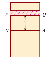
Let δ A = Area of the layer PQ.


Thus, the total stress is given by,

Moment of this total stress about neutral axis is given by,


Here the algebraic sum of all the moments present about the neutral axis should be equal to M. Therefore


The expression  represents the moment of inertia of area of the complete section about the neutral axis. Therefore,

Where I= moment of inertia,
We know that,

Therefore,

The above equation is also known as Bernoulli-Euler bending equation or Flexural Formula.
The equation applies to a member that is subjected to a constant bending moment and is not subjected to shear force. In practise, however, a member is loaded in such a way that the B.M. Varies from section to section and the shear force is not zero.
However, shear force is zero in the section where the bending moment is greatest. As a result, at such a section, the condition of simple bending can be assumed to be satisfied. As a result, the stresses produced by the maximum bending moment are obtained from the equation as shear forces at these sections, which are generally zero.
As a result, the theory and equations discussed in the preceding articles are quite sufficient and produce results that allow engineers to design beams and structures and calculate their stresses and strains with a reasonable degree of approximation where B.M. Is maximum.
Bending stresses in symmetrical sections
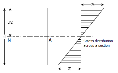
The neutral axis (N.A.) of a symmetrical section (such as circular, rectangular, or square) lies at d/2 from the outermost layer of the section where d is the diameter (for a circular section) or depth (for a rectangular or a square section). There is no stress at the neutral axis. But the stress at a point is directly proportional to its distance from the neutral axis. The maximum stress takes place at the outermost layer. For a simply supported beam, there is a compressive stress above the neutral axis and a tensile stress below neutral axis as shown below.
Key Takeaway:

Previously we discussed the theory of simple bending. In this theory, we assumed that no shear force is acting on the section. But in the actual work conditions when a beam is loaded, the shear force at a particular section always cause an effect, along with the bending moment. It has been observed that the effect of shearing stress, as compared to the bending stress, is quite negligible, and is not of much importance. But, sometimes, the shearing stress at a section assumes much importance in the design criterion.
Shear stress at a section:
Consider a small portion ABCD of length dx of a beam with bending moment varying from M to (M + dM) due to uniformly distributed load (U.D.L.) over its length dx. The distribution of compressive stresses due to bending moment is shown in Fig. Below.
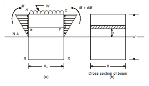
Let, M = Bending moment at AB
M + dM = B.M. At CD
F = Shear force at AB
F + dF = S.F. At CD
Consider elemental strip EF at a distance y from neutral axis (Fig.)
Let,
σ = Bending stress across AB at a distance y from neutral axis
σ + dσ = Bending stress across CD
I = Moment of inertia
By using flexure formula,

On face AB,

And on face CD,

Force acting across AB; FAB = stress on AB × Area

Similarly, force acting across CD.

Net unbalanced force on the strip.
DF = FCD – FAB


The total unbalanced force F above neutral axis can be found out by integrating from 0 to d/2.


But
 = First moment of area under consideration from neutral axis
Which is also given by,

Therefore,

This unbalanced force is balanced by a shearing stress τ acting along the length dx and width b.
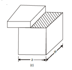


But,

Putting in main equation, we get,

Where,
S = Shear force at the section under consideration
A = Area above or below the layer under consideration
 = Distance of centroid of area under consideration from neutral axis
b = Width of the layer under consideration
I = Moment of Inertia of the section.
Shear stress distribution for various sections:
Shear stress distribution along Circular cross-section
Consider a circular section of diameter d as shown in Fig.(a).
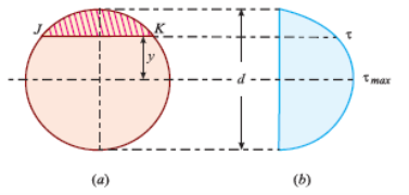
We know that the shear stress on a section JK at a distance y from the neutral axis as shown in fig. Above,

We know that in a circular section, width of the strip JK is given by,
 …i
…i
And, area of the shaded strip is given by,

Moment of this area about neutral axis is given by,

Now moment of the whole shaded area about the neutral axis may be calculated by doing the integration of the above equation between limits of y and r,

 …ii
…ii
We know that,


Differentiating, we get,


Putting y*dy in equation ii. We get,


We know that when y = y, width b = b and when y = r, width b = 0. Therefore, the limits of integration may be changed from y to r, from b to zero in equation,


Now, substituting these values in main equation, we get,


Substituting value of b obtained we get,

Thus, we again see that τ increases as y decreases. At a point, where y = r, τ = 0, = 0 and where y is zero, τ is maximum. We also see that the variation of τ with respect to y is a parabolic curve. We see that at neutral axis τ is maximum.
Substituting y=0 and I =  , we get,

Shear stress distribution diagram along rectangular cross-section
Consider a beam of rectangular section ABCD of width and depth as shown in Fig. (a). We know that the shear stress that is created on a section JK of the beam, at a distance of y from the neutral axis,

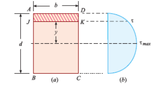
Where F = Shear force at the section,
A = Area of section above y (i.e., shaded area AJKD),
y = Distance of the shaded area from the neutral axis,
 = Moment of the shaded area about the neutral axis,
I = Moment of inertia of the whole section about its neutral axis, and
b = Width of the section.
Area of the shaded portion AJKD is given by,


Substituting these values in main equation, we get,

We see, from the above equation, that τ increase as y decreases. At a point, where y = d/2, τ = 0; and where y is zero, τ is maximum. We also see that the variation of τ with respect to y is a parabola. At neutral axis, the value of τ is maximum. Thus, substituting y = 0 and I =  , we get,

Shear stress distribution diagram along I cross-section
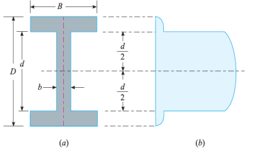
Consider a beam of an I-section as shown in Fig. (a)
Let B = Overall width of the section,
D = Overall depth of the section,
d = Depth of the web, and
b = Thickness of the web.
We know that the shear stress on a layer JK at a distance y from the neutral axis is given by,

Substituting all the values which are to be calculated by the procedure mentioned previously, we get,
- When y is greater than d/2

- When y is less than d/2

Shear stress distribution diagram along T cross-section
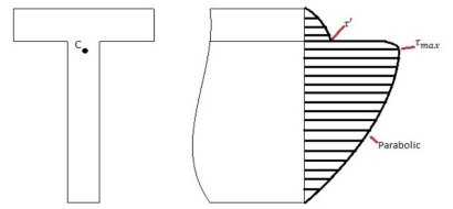
The calculation of the shear stress and all the parameters can be calculated in a similar way as mentioned earlier.
Key Takeaway:

A composite beam or a wooden flitched beam is a beam made up of two or more different materials that are assumed to be rigidly connected and behave like a single piece. For both materials, the strain at the common surfaces will be the same. In addition, the total moment of resistance will equal the sum of the moments of individual sections.
When such a beam is bent, the bending stresses and thus strains due to bending stresses at a point are proportional to the point's distance from the common neutral axis.
Consider the composite beam as shown:
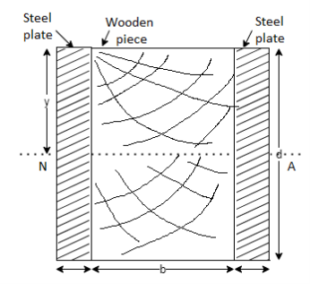
Let at a distance from the N.A., the stresses in steel and wood are f1 and f2 respectively.
 = Youngs modulus of steel plate
 = Moment of inertia of steel about N.A
 = Moment of resistance of steel
 = Youngs modulus of Wood
 = Moment of inertia of wood about N.A
 = Moment of resistance of wood
Strain in steel at a distance y from N.A.

Strain in wood at a distance y from N.A

Strain at the common surface is same,


Where, m is known as modular ratio,


Moment of resistance of steel and wood are given as,


Total Moment of resistance M


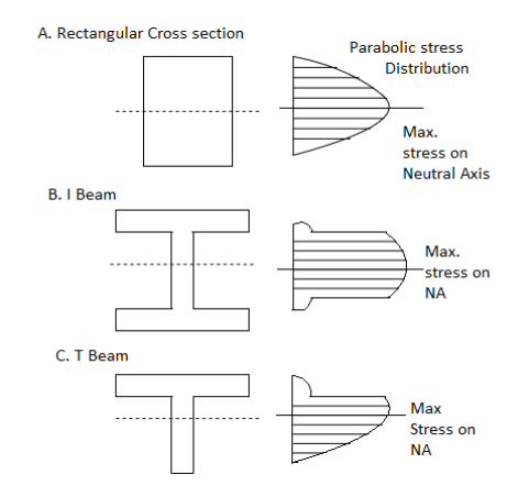
Shear stress distribution
Key Takeaway:

Types of Beams:
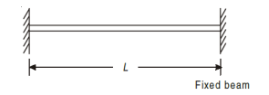
Fixed Beam
A beam whose both ends are rigidly fixed is called fixed (built in) beam.
Simply Supported Beam
Simply supported beams are those which have supports at both the ends. Generally, the beam is supported with a hinge or pin support at one end and a roller support at the other.
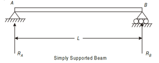
The roller support does not prevent translation in horizontal directions, but it prevents translation in the vertical direction.
Overhanging Beam
An overhanging beam is supported with either one or both ends extending beyond the supports. The extended portion of the beam acts like a cantilever.
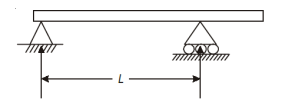
Fig. One end Overhanging

Fig. Both ends Overhanging
Cantilever beam
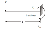
Cantilever beams are those whose one end is fixed and other is free. There is restriction for translation or rotation at the fixed end, thus both moment and force exist at the fixed end.
Continuous Beam
A beam supported at more than two points is called continuous beam.
Statically Determinate Beams
If the external support reaction can be found directly from the equation of static equilibrium, then these are statically determinate beams. Examples, simply supported beam, overhanging beam and cantilever beams.
Continuous and fixed beams are called statically indeterminate beams. The methods of statics are not sufficient to determine support reactions.
Types of Supports:
Roller Support
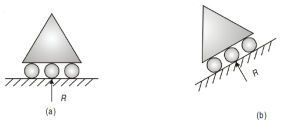
Roller support has only one reaction which is always normal to the contact surface.
Hinged Support
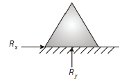
Hinged support has restriction to movement in x and y direction, therefore, it has two reactions Rx and Ry.
Fixed Support
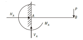
Fixed support has restriction to move in x and y direction as well as rotation about that point. It has three reactions i.e., VA, HA, MA.
Types of loading:
Concentrated or Point Load
A load which is acted at a point is called as point load.

Uniformly Distributed Load
A load which is uniformly spread over the beam is called as uniformly distributed load. (U.D.L).
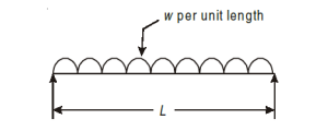
Equivalent point load = Intensity of load × Length = w × L
Act at C.G. Of loading i.e. (L / 2).
Uniformly Varying Load (U.V.L)
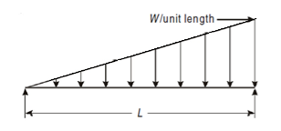
The intensity of loading increases or decreases at a constant rate is called as uniformly varying load (U.V.L) or triangular loading.
Equivalent point load = Intensity of load × Length

Act at C.G. Of loading i.e., at 2L/3 or L/3.
Sign conventions used for solving SFD and BMD problems:
Shear force is taken as positive if it tends to move the left portion upward with respect to right portion and vice-versa. A better rule of sign, which is easier to remember is to give a positive sign to those forces acting upward on the left portion.

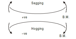
Bending moment is taken positive if it tends to sag (concave form) the beam, and if it is negative it tends to hog (convex shape)
Rules for Drawing SFD and BMD:
Below are some of the rules for drawing the SFD and BMD for various loading conditions:
- Shear force suddenly changes if the force applied is a point load (i.e., the shear force line is vertical). But the bending moment remains the same.
- If there is absence of any type of load or forces between two points, then the shear force remains constant (i.e., shear force line is horizontal). But the linearity is followed for Bending Moment (i.e., bending moment line is an inclined straight line).
- If there is a uniformly distributed load between two points, then the shear force changes linearly (i.e., shear force line is an inclined straight line). But the bending moment changes according to the parabolic law. (i.e., bending moment line will be a parabola).
- If there is a uniformly varying load between two points then the shear force changes according to the parabolic law (i.e., shear force line will be a parabola). But Cubic law is followed for the Bending Moment
If a beam carries uniformly distributed load or a point load, the beam is deflected from its original position. Due to the loads acting on the beam, it will be subjected to bending moment. The radius of curvature is given by,

The radius of curvature will be constant if,

The term  will be constant, if the beam is subjected to a constant bending moment M. This means that a beam for which, when loaded, the value
  is constant, will bend in a circular arc.
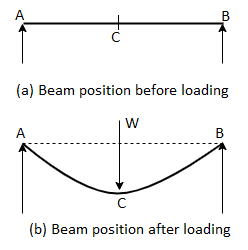
A uniform bending moment M is applied to a beam AB of length L. The beam will bend into a circular arc because it is subjected to a constant bending moment. The initial position of the beam is represented by ACE, while the deflected position is represented by AC'B.
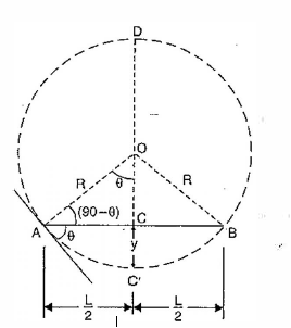
Let R = Radius of curvature of the deflected beam,
y = Deflection of the beam at the centre (i.e., distance CC'),
I = Moment of inertia of the beam section,
E = Young's modulus for the beam material, and
8 = Slope of the beam at the end A (i.e., the angle made by the tangent at A with the beam AB).
For a practical beam the deflection y is a small quantity.
Hence, 
 = Slope

Now, AC =BC = L/2
Also, from the geometry of a circle,
AC X CB = DC X CC'


For a practical beam, the deflection y is a small quantity. Hence the square of a small quantity will be negligible. Hence neglecting y2 in the above equation, we get


But from bending equation,


From triangle AOB, we know that


Relation between Slope, Deflection and Radius of Curvature:
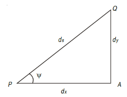
Consider a small portion PQ of a beam, bent into an arc (As shown in Fig.)
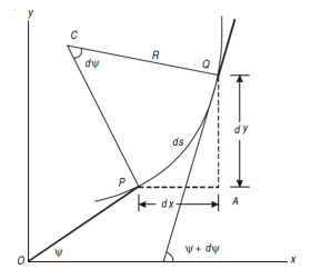
Let,
Ds = Length of beam PQ
R = Radius of the arc, into which the beam has been bent
C = Centre of the arc
Ds = Length of the beam PQ
R = Radius of the arc, into which the beam has been bent.
ψ = Angle, which the tangent at P makes with x – x axis, and
ψ + dψ = Angle which the tangent at θ makes with x – x axis
From the geometry of figure, we get,
∠PCQ = dψ
Ds = R *dψ
Considering ds = dx

We know that if x and y be the co-ordinates of point P, then

As  is small, tan
 =
=
Differentiating, we get,

We know that,


Substituting the value of (1/R), we get,

i.e.

The above-mentioned equation is known as Differential equation for bending, which also gives the relation between slope, deflection, and radius of curvature.
Differentiating the above equation w.r.t. x we get,


Differentiating the above equation w.r.t. x we get,


Simply supported beam Carrying a point load at center:
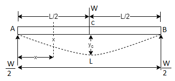


On Integrating,

For,  apply boundary condition,


Slope is maximum at A. At (A, x= 0)


On Integrating the slope equation, we get deflection equation,

For,  apply boundary condition,
At A, x= 0, Deflection is zero

Deflection is maximum at center C, where


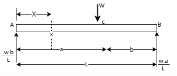
Simply supported beam Carrying an Eccentric point load:


Simply supported beam with UDL:
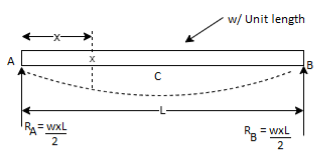


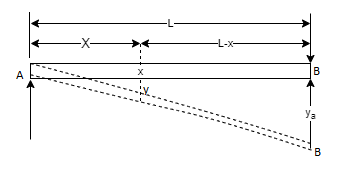
Cantilever Beam with point load at free end:


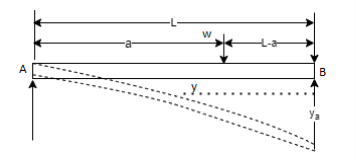
Cantilever Beam with point load at distance a from fixed end:


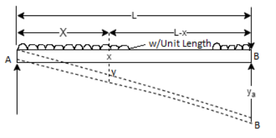
Cantilever Beam with UDL:


Cantilever Beam with UDL at distance a from fixed end:
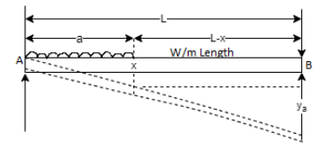


Cantilever Beam with UVL at distance a from fixed end:
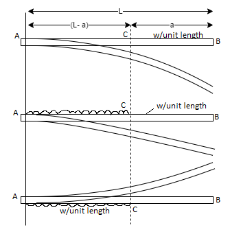
The slope and deflection at the point B is determined by considering,
- The whole cantilever AB loaded with a uniformly distributed load of w per unit length.
- A part of cantilever from A to C of length (L - a) loaded with an upward uniformly distributed load of w per unit length.


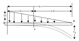
Cantilever Beam with UVL:


The procedure of finding slope and deflection for a simply supported beam with a load with general methods is a very laborious. There is a convenient method for determining the deflections of the beam subjected to loads. This method was devised by Mr. Special M.H. Manner Macaulay and is the known as Macaulay's method.
- In this method, bending moment at any section is expressed in systematic order.
- The section x is to be taken in the last portion of the beam.
- In this method, bending moment of each force or U.D.L. Is separated by a compartment of lines.
- Integrating bending moment equation, we will get slope equation.
- Again, integrating slope equation, we will get deflection equation
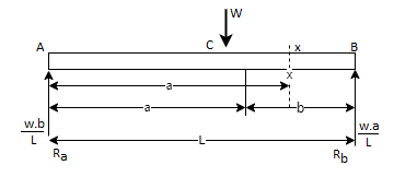
For example, consider a beam subjected to loading as shown in Fig. Below.
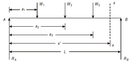
- Determine the support reactions.
- Consider a section x – x at a distance x covering all the loads from left end of the beam.
- Take moment of all forces about section x – x, considering sagging
- B.M. As positive and hogging as negative.

- Use differential equation of deflection i.e.,


- Integrating above equation, we get.

- Again, integrating above equation, we get

- The constant of integration c1 and c2 are calculated by applying boundary conditions.
- Substituting the value of constant, in equation obtained in step V gives general equation for slope and equation in step VI gives general equation for deflection
Key Takeaway:

- In this method, bending moment at any section is expressed in systematic order.
- The section x is to be taken in the last portion of the beam.
- In this method, bending moment of each force or U.D.L. Is separated by a compartment of lines.
- Integrating bending moment equation, we will get slope equation.
- Again, integrating slope equation, we will get deflection equation
Slope and deflection for all Standard Beams:
L = overall length W = point load, M = moment W= load per unit length | End slope | Max Deflection | Max bending moment |
 |  |  | M |
 |  |  | WL |
 |  |  |  |
 |  |  | M |
 |  |  |  |
 |  |  |  |
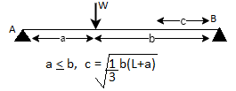 |   |  (At position c) |  (Under load) |
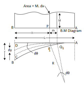
A beam AB carrying some type of loading, and hence subjected to bending moment. Let the beam bent into  as shown,
Due to the load acting on the beam. Let A be a point of zero slope and zero deflection.
Consider an element PQ of small length dx at a distance x from B. The corresponding points on the deflected beam are  as shown,
Let R = Radius of curvature of deflected part 
 = Angle subtended by the arc
  at the center o.
M = Bending moment between P and Q
 = Tangent at point
 = Tangent at point
The tangent at P1 and Q1 are cutting the vertical line through B at points C and D. The angle between the normal at P1 and. Q1 will be equal to the angle between the tangents at P1 and Q1. Hence the angle between the lines CP and DQ will be equal to  .
.
For the deflected part P1Q1 of the beam, we have,


Since the slope at point A is assumed zero, hence total slope at B is obtained by integrating the above equation between the limits 0 and L.

But M.dx represents the area of B.M. Diagram of length dx. Hence  represents the area of B. M. Diagram between A and B.


If the slope at A is not zero then, we have,
“Total change of slope between B and A is equal to the area of B. M. Diagram between B and A divided by the flexural rigidity EI”

Now the deflection, due to bending of the portion P1Q1 is given by,


Since deflection at A is assumed to be zero, hence the total deflection at B is obtained by integrating the above equation between the limits zero and L.

 represents the moment of area of the B.M. Diagram of length dx about point B.

This is equal to the total area of B.M. Diagram between B and A multiplied by the distance of the C.G. Of the B.M. Diagram area from B.

A = Area of B.M. Diagram between A and B
 = Distance of C.G. Of the area A from B
Key Takeaway:

A beam whose both ends are fixed is known as a fixed beam. Fixed beam is also called a built-in or encaster beam. In case of a fixed beam both its ends are rigidly fixed and the slope and deflection at the fixed ends are zero. But the fixed ends are subjected to end moments Hence end moments are not zero in case of a fixed beam.
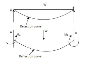
In case of simply supported beam, the deflection is zero at the ends. But the slope is not zero at the end.
In case of fixed beam, the deflection and slope are zero at the fixed ends The slope will be zero at the ends if the deflection curve is horizontal at the ends bring the slope back to zero (i.e., to make the deflection curve horizontal at the fixed ends)
The end moments MA and MB will be acting in which MA will be acting anti-clockwise and MB will be acting clockwise.
A beam which is supported on more than two supports is known as continuous beam.
Bending Moment Diagram:
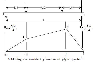
A simply supported beam subjected to given vertical loads
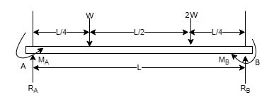
Taking moment about, A


BM at A | = 0 |
BM at B | = 0 |
BM at C = 0 |  |
BM at D = 0 |  |
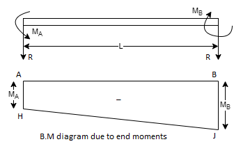
A simply supported beam subjected to end moments only
MA = Fixed end moment at A
MB = Fixed end moment at B
R = Reaction at each end due to these moments.
As the vertical loads acting on the beam are not symmetrical the fixed end moments will be different. Suppose MB is more than MA and reaction R at B is acting upwards. Then reaction R at A will be acting downwards as there is no other load on the beam.
Taking moments about A, we get clockwise moment at A = Anti-clockwise moment at A.


As MB has been assumed more than MA, the R.H.S. Of equation (A) will be positive. This means the magnitude of reaction R at B is positive. This also means that the direction of reaction R at B is according to our assumption. Hence the reaction R will be upwards at B and downwards at A.
Since the directions of the two bending moments are opposite to each other, therefore their resultant effect may be obtained by drawing the two moments on the same side of the base AB.
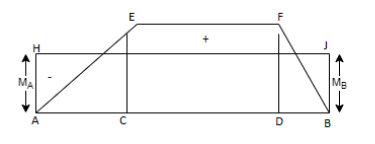
Final Reactions 


Find 

 B.M. At any section at a distance x from A due to end moments.
The resultant B.M. At any section at a distance x from A = 

Integrating the above equation for the entire length, we get

And slope  at the fixed ends i.e., at A and B are zero


Substituting and solving


Since slope and deflection at A and B are zero, hence  are 0
are 0


Hence the distance of C.G. Of B.M. Diagram due to vertical loads from A is equal to the distance of C.G. Of B.M. Diagram due to end moments from A.
Now, MA & MB Can be calculated.
Slope and deflection for a fixed beam carrying a point load at the center:
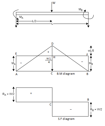


Slope and deflection For Various Beams
Eccentric load point |  | 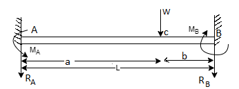 |
UDL |  |  |
Key Takeaway:


“A member which is subjected to the couple which produce rotation about longitudinal axis is known as Twisting Moment or Torsion.”
- Due to torque applied on shaft, the shaft produced shear stress and shear strain in the materials.
- In practice, torque is produced in shaft of motors or power equipment. e.g., Fans, axles of vehicles, pumps, etc.
When a force is applied tangentially to a cylindrical rod, at a certain radius, in the plane of its transverse cross-section, the rod is said to be subjected to twisting moment or torque. Torsion is also defined as the product of tangential force and the radius.
Figure below shows a circular shaft of length l and diameter d acted upon by a torque T.

The shear strain  of elements at radial distance r form the axis is constant for a particular value of T. The line OA thus twists to OB.
Let  be the angle of twist of a cross-section relative to another cross-section at a distance l apart. Then,


Now, tangential force on the element = 
Moment of tangential force on the element = 
Sum of moments for the whole shaft, 


But  is the polar moment of inertia of the shaft,
Thus


From (i) and (ii)

This equation is called as Torsion Equation.
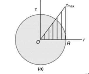
Torsion equation shows that for a given shaft, shear stress is proportional to the radius of shaft. Figure below shows a shear stress distribution in solid shaft of Radius R.
Assumptions in Torsion Theory:
- The bar is acted upon by a pure torque.
- The section under consideration is remote from the point of application of the load and from a change in diameter.
- Adjacent cross sections originally plane and parallel remain plane and parallel after twisting, and any radial line remains straight.
- The material obeys Hooke’s law
- Cross-sections rotate as if rigid, i.e., every diameter rotates through the same angle
Basic Torsion Formulae:
Polar Moment of Inertia
Polar moment of Inertia for solid circular shaft with diameter D is given as

Polar moment of Inertia for hollow circular shaft with outer diameter D and inner diameter d is given as

Polar Sectional Modulus
Polar sectional modulus is the ratio of sectional modulus to the maximum radius of shaft.
Mathematically,


For solid shaft,


For hollow shaft,


Now, we have from torsion equation,


The ability of shaft to resist the motion of twisting moment is called as strength of a shaft.
Torsional Stiffness
It is the torque required to produce unit angle of twist
It is given by,

Torsional Flexibility
It is the angle of twist produced by a unit torque applied


Torsional Rigidity
Torsional rigidity is the product of modulus of rigidity G and polar moment of inertia J
It is given by,

Torsion in stepped and composite shaft:
Stepped or composite shaft are either in series or parallel
Shafts in series:
When the two shafts are joined in series and a single torque is applied, both shafts are subjected to same torque.
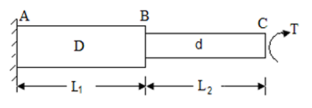


Also

The angle of twist for the shafts in series is the sum of the angle of twist of each shaft


Shaft in Parallel:
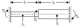
When the two shafts are joined in parallel, the torque applied to the composite shaft is the sum of the torques on the two shafts


The angle of twist in the shafts in parallel is same


Torque Transmission:
Torque on strength basis
When the shaft is subjected to pure torsional moment, the torsional shear stress is given,


Therefore,

Torque on rigidity basis
From Torsion equation, we have,

Value of  in the above equation is in radian. Converting it into degrees

For solid shaft, we have

Therefore,


Where,  is in degree.
Torque found by strength basis and by rigidity basis is maximum torque.
Therefore,

Power transmission by shaft
It is the product of average torque and corresponding angle turned per unit duration of time.


Where, N is in rpm

The relation between average torque and maximum torque is

Where C is a constant,
Generally,

Torsional Resilience:
Torsional resilience is the strain energy stored within the elastic limit in a body (column or strut) subjected to torsion.
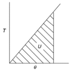
The total strain energy of shaft under the action of torque is the work done in twisting. Thus, for gradually applied torque T to the shaft of length  is
is

For solid shaft,


Therefore,


Torsional Resilience is nothing but the average strain Energy
Therefore,

Now,
Strain Energy per unit volume = 
As shear stress varies linearly. i.e., zero at axis and maximum at surface of shaft. Similarly strain energy also varies linearly. i.e., zero at axis and maximum at surface of shaft
Total strain energy is given by


Proof Resilience is defined as the maximum strain energy which can be stored in a body within an elastic limit is called as proof resilience.
In this case,

Key Takeaway:


This condition of combined bending and torsion is common in shafts that transmit torque. The shafts are subjected to twisting as well as bending moments caused by gravity or inertia loads. Bending moment, torque, and shear force all contribute to the formation of stresses in such cases. Shear stress due to shear force, on the other hand, is usually unimportant because its maximum value occurs at the neutral axis, where the bending stress is zero.


As, Polar moment of inertia,

For circular shaft

For solid shaft


For Hollow shaft


Max Principal Stress,

For Solid Shaft:


Where,

Is equivalent bending moment which would give the same bending stress
Max Shear Stress,


Where,

Is equivalent bending moment which would give the same bending stress
Strain Energy,

Where,


Similarly for Hollow shaft it can be derived.
Key Takeaway:


Consider a thin-walled closed tube acted upon by a torque T in a traverse plane as shown in figure.
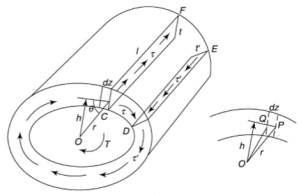
It may be assumed that the shear stress at a point across the thickness of the tube wall is constant.
Let  be the shear stress at point C where thickness is
  and
and  be the shear stress at point D where thickness is
Consider the strip CDEF,
For the equilibrium of the strip,


i.e., product of shear stress and thickness is constant at all the points on the periphery. This is the shear flow and is constant.
Let dz be the elemental length round the circumference. Then,
Force on the element = 
Moment about O is given by,

Where h is the perpendicular distance of shear vector from O.
Therefore,


Where, A is the area enclosed by mean circumference.
Now, Strain energy is

Also Strain energy is given by,


Therefore,


If shear stress is constant,


Where, Z is the Circumference of the thin-walled tube.
Since,


Therefore,


Hence,

Key Takeaway:

References:
- Strength of Materials – S.S Rattan (2nd Edition Tata McGraw Hill)
- Strength of Materials – R.K. Bansal (4th Edition Lakshmi Publication)
- Mechanics of Materials – Ferdinand P. Beer, E. Russell Johnston (6th Edition McGraw Hill)
- Mechanics of Materials – James M. Gere, Barry J. Goodno (Brief Edition CENGAGE Learning)
- Mechanics and Strength of Materials - Vitor Dias da Silva (1st edition Springer)
- Elements of strength of materials by Timoshenko (2nd Edition)
- Mechanics of Materials (Gere & Timoshenko 2nd edition)
- Strength of Materials (Timoshenko Volume I & II)