Unit - 3
Helical and Leaf Springs
Springs
Springs are energy absorbing units whose function is to store energy and to restore it slowly or rapidly depending on the application. A spring can be made of any elastic material that deforms when subjected to a force. A spring's primary job is to deflect under load and to revert to their original shape when the load is removed. When members deform significantly because of forces acting on them but do not go over a safe stress limit, the term "buckling" is commonly employed
Springs are classified bases on load bearing capacity which depends on various factors such as total number of coils, coil gaps, wire shapes, etc.
Deflection of springs by energy method
Strain energy stored in beam is,

Strain energy in torsion,
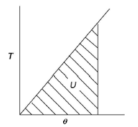


For solid shaft,


Therefore,


This is Strain energy over the whole shaft. However, the shear stress varies from zero at the axis to maximum at outer surface. So, intensity of strain energy is also not uniform and varies across the cross section.
Thus, total strain energy,


Under axial Load:


Under axial Torque/ Twist:
Maximum strain energy/ Unit volume

Total strain energy due to bending moment,

Equating,

Key Takeaway:


Helical spring: They are made of wire coiled into a helical form; the load being applied along the axis of the helix. In this type of springs, the major stresses are torsional shear stress due to twisting. They are both used in tension and compression. Helical springs are used in various applications due to their shock absorption and load bearing properties.
Open Coiled Helical Springs: These helical springs are designed to resist compression, which is they are known as compression springs. These springs are not wound tightly and have a high pitch. This results in large spaces between the coils, which also makes the springs very recognizable. Hence, no two turns of a spring will lie on the same axis of the helix. The turns of these springs are located at inclined angles towards the helical axis. Some typical applications include ball point pens, valve assemblies in engines, car suspension systems, pogo sticks, etc.
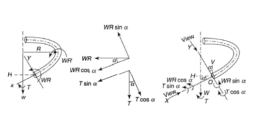
Let  be the angle of helix and let the following axes be in a vertical plane tangential to the helix at O.
OH = Horizontal axis
OV = Vertical axis
OX= Polar axis or axis of twist at any normal cross-section inclined at angle  to OH OY = Bending axis about which bending takes place inclined at angle
  to OV.

W = axial load
T = axial torque
The axial load W produces a couple WR about OH.
WR  that tends to twist the wire
WR sin  that tends to open the coil or to reduce the curvature
The axial torque T about OV
T that tends to twist the wire
T sin  that tends to open the coil or to reduce the curvature


Axial deflection and axial rotation may be obtained using Castigliano 's theorem.
Axial Deflection:

For axial load (T =0)


For axial torque (W=0)


Axial Rotation:

For axial load (T=0)


For axial Torque (W =0)


Stresses:


Axial load only:


Axial torque only:


Example:1:
An open-coiled helical spring has 12 turns wound to a mean diameter of I 00 mm. The angle of the coils with a plane perpendicular to the axis of the coil is 30°. The wire diameter is 8 mm.
Determine The axial tension with a load of 80 N & the angle turned by the free end if free to rotate
E =205 GPa & G =80 GPa
Answer:
Axial extension


Angle turned


Key Takeaway:

Closed Coiled Helical Springs: Designed to resist stretching and twisting, these springs are also known as tension/extension springs. These springs feature an eye or a hook at the end for attachment. These springs can endure stress caused by high torsion or bending. The coils are closely wound to each other and lie on the same axis of the helix. The turns of this spring lie at 90 degrees to the axis of the helix. These springs are used for heavy duty applications such as carburettors, garage door assemblies, vice-grip pilers, etc.
Under axial Load:
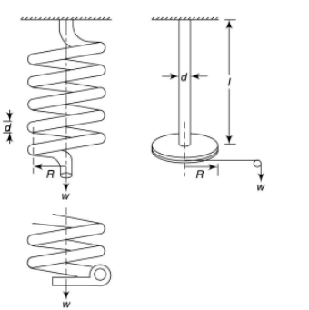
W = Axial load
D = mean coil diameter
R = mean coil radius
d =diameter of wire
 = Deflection of W along the axis of the coils
L = length of wire

Work done by axial force to torsional strain energy,


l= length of wire = 

Deflection of the spring,

Also,

Stress,


For most springs,


Applicable to springs of thin wires where D/d ratio is more than 20.
Wahl's correction: This is a method to incorporate the effects of direct shear and the curvature and is based on the experimental investigations of A H Wahl. According to him, the maximum stress in the spring wire can be expressed as,

Wahl’s stress concentration factor is given by

Where C is spring index=D/d
Key Takeaway:


Under axial Torque/ Twist:
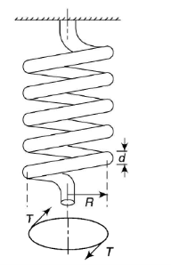
The axial torque T tends to wind up the spring by producing approximately a pure bending moment at all cross-sections.
When bending moment is applied to curved bars with small curvature (T is the applied bending moment).

Where R and R' are the radii of curvature before and after applying the bending moment.
Let n and n' be the number of turns of the spring before and after applying the bending moment.
Then,
l= length of wire = 


Example:2:
A dose-coiled helical spring having 24 turns is made of 8-mm diameter wire. The mean diameter of the spring is 80 mm, and it carries a load of 250 N. Determine the shear stress developed, the deflection and the stiffness of the spring. Take G = 84 GPa.
Answer:
Shear stress

Deflection

Stiffness

Springs in Series:


Springs in Parallel:


For Square Cross Section the procedure is like Circular cross-section, just put,

Example:3:
A composite spring consists of two dose-coiled helical springs connected in series. Each spring has 14 coils at a mean diameter of 20 mm. The stiffness of the composite spring is 800 Nm. If the wire diameter of one spring is 2.5 mm, find the wire diameter of the other. What will be the maximum load which can be carried by the composite spring and the corresponding deflection for a maximum shear stress of 150 MPa! G = 78 GPa.
Answer:
Determination of wire diameter
For springs in series, 


Load and deflection

Load and deflection
Total deflection

Key Takeaway:


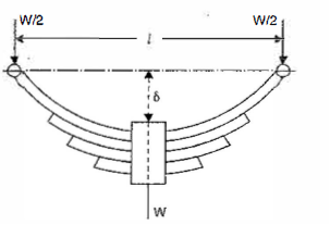
b = Width of each plate
n = Number of plates
l = Span of spring
 = Maximum bending stress developed in the plates
t = Thickness of each plate
W = Point load acting at the center of the spring and
 = Original deflection of the top spring


Moment of inertia


Total resisting moment by n plates,

As the maximum B.M. Due to load is equal to the total resisting moment, therefore,


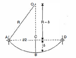
From triangle ACO,


As,


Example :4:
A leaf spring of semi-elliptical type having 8 plates is 1 m long. The metallic plates have a proof stress in bending of 600 MPa. Each plate is 60 mm wide and 12 mm thick. Find the initial radius of the plates. Also find the height from which a load of 400 N may fall on the center of the spring if the maximum stress so produced is one half of the proof stress. E = 204 GPa.
Answer:
Initial radius

At proof load R’ is the infinite and thus 
At proof load,  is infinite and thus


Determination of equivalent static load
Let  be the equivalent static load which produces the same maximum stress and deflection as the impact load
Also 
As the maximum stress is one half of the proof stress,


Height of drop

Now W(h+δ)


Key Takeaway:


A member of a structure that is subjected to axial Compressive load is referred to as a column or strut. The member is known as a column if it is vertical and both of its ends are permanently attached while subjected to axial compressive load, such as a vertical pillar between the roof and the floor. A strut is a structural element that is not vertical and has both ends hinged or pin connected. Struts, connecting rods, and piston rods are examples of struts.
The failure of a column takes place due to the anyone of the following stresses set up:
- Direct compressive stress
- Buckling stress
- Combined stress
Failure of Short Column:
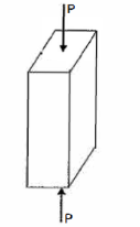

If the compressive load on the short column is gradually increased, a stage will reach when the column will be on the point of failure by crushing. The stress induced in the column corresponding to this load is known as crushing stress and the load is called crushing load.
 = Crushing load,
 = Crushing stress, and
A = Area of cross-section.

All short columns fail due to crushing.
Failure of long Column:

The load at which the column just buckles, is known as buckling load or critical just or crippling load. The buckling load is less than the crushing load for a long column. The value of buckling load for long columns is low whereas for short columns the value of buckling load is relatively high.
Let,
l = Length of a long column
P = Load (compressive) at which the column has just buckled
A = Cross-sectional area of the column
e = Maximum bending of the column at the center
 = Stress due to direct load =
 = Stress due to bending at the center of the column =
Z = Section modulus about the axis of bending.
The extreme stresses on the mid-section are given by,


The column will fail when maximum stress is more than the crushing stress. But in case of long columns, the direct compressive stresses are negligible as compared to buckling stresses. Hence very long columns are subjected to buckling stresses only.
The following assumptions are made in the Euler's column theory:
- The column is initially perfectly straight, and the load is applied axially.
- The cross-section of the column is ·uniform throughout its length.
- The column material is perfectly elastic, homogeneous, and isotropic and obeys Hooke's law.
- The length of the column is very large as compared to its lateral dimensions.
- The direct stress is very small as compared to the bending stress.
- The column will fail by buckling alone.
- The self-weight of column is negligible.
Critical load is the only load for which the structure will be in equilibrium in the disturbed position. If the load on the strut or column exceeds this value, then the column will fail by buckling. At this value the structure is in equilibrium regardless of the magnitude of the angle. At this value, restoring effect of the moment in the spring matches the buckling effect of the axial load represents the boundary between the stable and unstable conditions.
If the axial load is less than Pcr the effect of the moment in the spring dominates and the structure returns to the vertical position after a small disturbance – stable condition.
If the axial load is larger than Pcr the effect of the axial force predominates and the structure buckles – unstable condition.
Because of the large deflection caused by buckling, the least moment of inertia I can be expressed as,

Where, A is cross-sectional area of column or strut.
K is the radius of gyration and is given by

Note: The smallest radius of gyration of the column, i.e., the least moment of inertia I should be taken in order to find the critical stress.
According to Euler’s Theory, Euler’s critical load is given by,

Where,  is Equivalent length of column (1st mode of bending)
Slenderness Ratio is referred as the ratio between the length and least radius of gyration.
It is denoted by 

We have,

And

Therefore,


In Euler’s theory, following cases may be considered.
Both end’s hinged
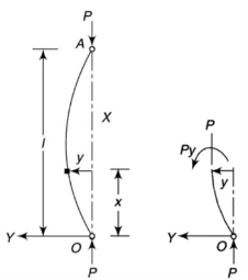
Y-axis is taken in such a way that deflection is positive.
From the equation of bending, viewing from right end,

The equation can be written as

Where, 
The solution of the above equation is

When both ends are hinged.
At  ,
, 

And at  ,
, 

If A = 0, y is zero for all values of load, hence, there is no bending.


Therefore, Euler’s Crippling load,


Comparing above equation with

We get,

Both ends fixed
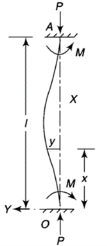
Let M be the end fixing moments, then governing equation becomes,

The equation can be written as

Where, 
The solution of the above equation is


When one end is fixed and other is free.
At  ,
, 

At  ,
, 


At  ,
, 


Therefore, Euler’s Crippling load,


Comparing above equation with

We get,

One end fixed and other free
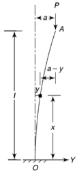
Take Y-axis towards right for positive value of y. Viewing from left we get,

The equation can be written as

Where, 
The solution of the above equation is


When one end is fixed and other is free.
At  ,
, 

At  ,
, 


At  ,
, 


Therefore, Euler’s Crippling load,


Comparing above equation with

We get,

One end fixed and other hinged
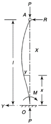
Let M be the fixing moment at end O.
For equilibrium of strut, a horizontal for R acts at free end
Then,

The equation can be written as

Where, 
The solution of the above equation is


When one end is fixed and other is free.
At  ,
, 

At  ,
, 


At  ,
, 


Therefore, Euler’s Crippling load,


Comparing above equation with

We get,

Limitations of Euler’s Theory:
Crippling stress is given by,

The critical stress is directly proportional to modulus of elasticity and inversely proportional to square of slenderness ratio of column.
The graph plotted between critical stress and slenderness ratio is shown in figure below.
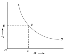
The value of  at point B is called as critical value of slenderness ratio.
For any slenderness ratio above this value, column fails for buckling and for any value of slenderness ratio less than this value, the column fails by crushing and not by buckling.
Hence, for short column, Euler’s Formula is not applicable.
Mathematically, Euler’s Formula is applicable,
If crushing stress  buckling stress


When the slenderness ratio is greater than or equal to  , then the Euler’s formula is applicable. This is the limitation of Euler’s formula.
Crippling Stress


Example:1:
Using Euler’s Formula, determine the critical stresses for the strut of slenderness ratio 80,120, 160 and 200 under a condition of (a) both ends hinged and (b) both ends fixed. Take E = 205 GPa.
Answer:
Given A strut with slenderness ration 80, 120, 160 and 200 and with both ends hinged and both ends fixed.
To find critical stresses
Both ends hinged
For both ends hinged 

(ii) 
(iii) 
(iv) 
Both ends fixed


When forces of different magnitude and direction on a particular member, are acting on structures the resultant of all the forces will act in a specific direction and magnitude. The point through which this resultant force passes should be within the middle third of the base of this member to avoid tensile stresses. This is known as middle third rule.
Example:
Because tensile load weakens cement concrete columns, we must ensure that no tensile load is applied anywhere in the section, and so load must be provided in such a way that no tensile stress is created in the section of cement concrete columns.
As previously stated, when a body is subjected to an axial tensile or axial compressive load, only direct stress is produced in the body. Similarly, when a body is subjected to a bending moment, only bending stress is produced in the body.
Consider a body that is subjected to axial tensile or compressive loads as well as bending moments; in this case, direct stress and bending stress will be produced in the body.
If an eccentric load is applied to a column, direct and bending stresses will develop in the column, and we can calculate the resultant stress created at every point in the column by adding direct and bending stresses algebraically.
We'll treat compressive stress as positive, tensile stress as negative, and the resultant stress value will be available at any point in the column section. In the column portion indicated here, there will be maximum and lowest stress.


If minimum stress σ Min = 0, it indicates that there will be no stress at the respective point in the section.
If minimum stress σ Min = Negative, it indicates that there will be tensile stress at the respective point in the section.
If minimum stress σ Min = Positive, it indicates that there will be compressive stress at the respective point in the section.
For, a Rectangular Section,
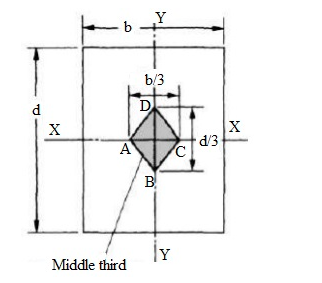

Minimum stress (σ Min) must be greater or equal to zero for no tensile stress at any point along the width of the column.


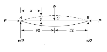
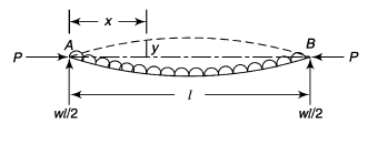
Columns carry axial compressive load. If the column is also subjected to transverse load, then they are known as beam columns. The transverse load is generally uniformly distributed.
Shruts with eccentric loading:
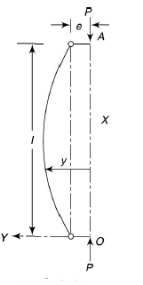


Shruts with lateral loading:
Concentric loading at centre:


Uniformly Distributed load:


Example:3:
A 4-m long steel tie bar with a diameter of 32 mm is supported horizontally through pin joints. · Determine the maximum tensile stress in the bar if it sustains an axial pull of 15 kN. Density of steel is 7600 kg/m3 and Eis 205 GPa.
Answer:
Maximum bending moment


 of length


Maximum tensile stress

Since the tension in the column remains elastic, Euler's theory of column buckling is utilized to calculate the critical buckling load. When a column is on the verge of buckling, the critical buckling load is the greatest load it can withstand. Buckling failure occurs when the column's length exceeds its cross-section.
Certain assumptions about the site of axial load application, column material, cross-section, stress limits, and column failure underpin Euler's theory. The validity of Euler's theory is predicated on the occurrence of buckling failure
This hypothesis ignores the effect of direct column stress, the presence of crookedness in the column, and possible axial load application point deviations from the center of the column cross-section. As a result, the critical buckling load may be overestimated by the theory.
Euler’s Theory
The Euler’s theory states that the stress in the column due to direct loads is small compared to the stress due to buckling failure. Based on this statement, a formula derived to compute the critical buckling load of column. So, the equation is based on bending stress and neglects direct stress due to direct loads on the column.
Assumptions
- Initially, the column is perfectly straight.
- The cross-section of the column is uniform throughout its length.
- The load is axial and passes through the centroid of the section.
- The stresses in the column are within the elastic limit.
- The materials of the column are homogenous and isotropic.
- The self-weight of the column itself is neglected.
- The failure of the column occurs due to buckling only.
- Length of column is large compared to its cross-sectional dimensions.
- The ends of the column are frictionless.
- The shortening of column due to axial compression is negligible.
Limitations
- The possibility of crookedness in column is not accounted for in this theory, and the load may not be axial.
- The axial stress is not considered in the formula derived in Euler theory of column buckling, and the critical buckling load may be greater than the actual buckling load.
If both ends are pined
 where
where 
If one end is pined & other fixed
 where,
Example:
Using Euler's formula, determine the critical stresses for a strut of slenderness ratio 80, 120 and 160 and 200 under the condition of (a) both ends hinged, and (b) both ends fixed. E = 205 GPa.
Answer:
To find critical stresses
Both ends hinged
For both ends hinged 

(ii) 
(iii) 
(iv) 
Both ends fixed


Condition | Equivalent Length | P critical |
Both end’s hinged |  |  |
Both ends fixed | 
|  |
One end fixed and other free | 
| 
|
One end fixed and other hinged |  | 
|
Euler’s formula is applicable to long columns in which l/k ratio is larger than a certain value for a particular material. Also, direct compressive shear is not considered, therefore it gives correct result for very long columns only. For columns of medium length Rankine formula is used where results are not accurate according to Euler’s formula.


- For Long columns
 is very small,
- For short columns
 is very large,


Where,


Example:
A 3.2 m long fixed end hollow cast iron column with ID as 60 mm & OD as 80 mm. Crushing stress = 500 Mpa & Rankine constant is 1/1600. Use Ranking crippling load.
Answer:
Determination of 


Rankine’s crippling load
 for both ends fixed

Key Takeaway:


Condition | Equivalent Length | P critical |
Both end’s hinged |  |  |
Both ends fixed | 
|  |
One end fixed and other free | 
| 
|
One end fixed and other hinged |  | 
|
Machine tool structure:
Beds:
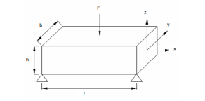
The machine tool beds consist of partially or fully closed box sections with ribs, partitions, etc. Beds are usually used in machine tools with wall arrangements and are evaluated as bars subjected to bending and torsion.
Sr. No. | Wall Arrangement | Application |
1 | Covered top closed profile bed | These are used in boring, Plano-milling and slotting machines. |
2 | Open top closed profile bed. | These are used in grinding machines. They are also used when the bed is also required to serve as an oil reservoir. |
3 | Beds on legs: without stiffening diagonal wall. | These are used in lathes, turrets etc. |
4 | Beds on legs: without stiffening wall with 30-40% higher stiffness than (3). | These are used in multiple tool and high production lathes. |
5 | With stiffening wall and provision of chip disposal through opening in rear wall | These are employed in large sized lathes and turrets. |
6 | With stiffening wall | These are used in large size lathes and turrets. |
Design of columns:
Sl. No. | Section | Application |
1 | Square box type section with vertical ribs and spaced horizontal stiffeners. | It is used for columns subjected to three-dimensional loading, chief application is in boring and milling machines. |
2 | Rectangular box type section. | It is used when forces act only in the plane of symmetry. It is used in vertical drilling and unit built in machine tools. Optimum a/b = 2 to 3 |
3 | Rectangular box type section with vertical ribs and spaced horizontal stiffeners. | It is used in gantry type machine tools. The recommended a/b ratios are: For vertical lathe a/b = ¾, for planning machine a/b = 2-3, for Plano-mailing machine a/b ratio = 2-3. |
4 | Circular section with stiffeners. | It is used when the load is small and it is necessary to provide for rotation of the column, e.g., in radial drilling machine and |
Heat exchangers, testing machines, Pressure vessels, Push rods of valve mechanisms, piston rods in hydraulic / pneumatic cylinders, connecting rods, power screws etc.
References:
- Strength of Materials – S.S Rattan (2nd Edition Tata McGraw Hill)
- Mechanics of Materials – Ferdinand P. Beer, E. Russell Johnston (6th Edition McGraw Hill)
- Mechanics of Materials – James M. Gere, Barry J. Goodno (Brief Edition CENGAGE Learning)
- Mechanics and Strength of Materials - Vitor Dias da Silva (1st edition Springer)
- Elements of strength of materials by Timoshenko (2nd Edition)
- Mechanics of Materials (Gere & Timoshenko 2nd edition)
- Strength of Materials (Timoshenko Volume I & II)
- Strength of Materials by Timoshenko and Young, (East West Press)