Unit - 4
Thin cylinders & Spheres and Thick cylinders
Fluid-pressured cylinders and spheres are common in engineering practises such as steam boilers, tanks, engine chambers, reservoirs, and so on. These can also be referred to as pressure vessels or shells. Stresses are induced in the walls of a pressure vessel because of internal or external pressure, and the thickness can be determined while designing. There are three main stresses in a cylindrical vessel: circumferential or hoop stress, longitudinal stress, and radial stress.
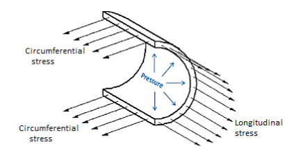
These vessels are generally used for storing fluids (liquid or gas) under pressure. The walls of such vessels are thin as compared to their diameters. If the thickness of the wall of the cylindrical vessel is less than  of its internal diameter, the cylindrical vessel is known as a thin cylinder. In case of thin cylinders, the stress distribution is assumed uniform over the thickness of the wall.
The ratio of the thickness of the wall to the diameter of the shell determines whether a shell is thin or thick. A shell is considered thin if the ratio is less than about 1 to I 5, otherwise it is thick. In a thin shell, the hoop stresses are assumed to be constant throughout the thickness, and the radial stress is small and can be ignored.
The ratio between the mean radius of the vessel and the thickness of the wall determines whether a pressure vessel has thin or thick walls. If this ratio is greater than 10, the vessel is classified as having a thin wall pressure. If the ratio is less than 10, the vessel is classified as having a thick wall pressure.
A thick-walled pressure vessel develops more (circumferential) stress on the inside surface of the vessel, which decreases as the vessel diameter increases.
Radial stress is negligible in thin pressure vessels and is ignored; however, in thick pressure vessels, radial stress is considered alongside longitudinal and transverse stress.
Thin-Walled Cylinder:
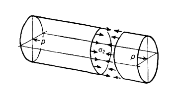
A problem in which combined stresses are present is that of a cylindrical shell under internal pressure. Suppose a long circular shell is subjected to an internal pressure p, which may be due to a fluid or gas enclosed within the cylinder.
The internal pressure acting on the long sides of the cylinder gives rise to a circumferential stress in the wall of the cylinder; if the ends of the cylinder are closed, the pressure acting on these ends is transmitted to the walls of the cylinder, thus producing a longitudinal stress in the walls.
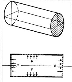
Long thin cylindrical shell with closed ends under internal pressure
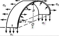
Circumferential and longitudinal stresses in a thin cylinder with closed ends under internal pressure
Suppose r is the mean radius of the cylinder, and that its thickness t is small compared with r. Consider a unit length of the cylinder remote from the closed ends. Suppose we cut this unit length with a diametral plane. The tensile stresses acting on the cut sections are  , acting circumferentially, and
  , acting longitudinally. There is an internal pressure p on the inside of the half-shell. Consider equilibrium of the half-shell in a plane perpendicular to the axis of the cylinder, the total force due to the internal pressure pin the direction OA is,

Because we are dealing with a unit length of the cylinder. This force is opposed by the stresses ; for equilibrium we must have,


We shall call this the circumferential (or hoop) stress.
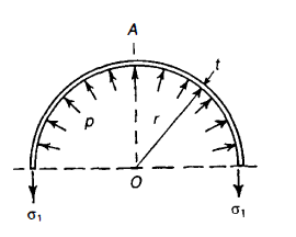
Derivation of circumferential stress
Derivation of longitudinal stress
Now consider any transverse cross-section of the cylinder remote from the ends the total longitudinal force on each closed end due to internal pressure is,

At any section this is resisted by the internal stresses,  For equilibrium we must have,


We shall call this the longitudinal stress
Thus, the longitudinal stress is only half the circumferential stress.
The stresses acting on an element of the wall of the cylinder consist of a circumferential stress  , a longitudinal stress
  , and a radial stress P on the internal face of the element.
As (r/t) is very much greater than unity, p is small compared with  and.
and.  , the state of stress in the wall of the cylinder approximates then to a simple two-dimensional system with principal stresses
  &
&  .
.
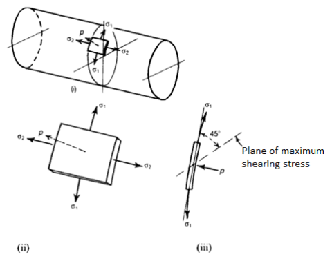
Stresses acting on an element of the wall of a circular cylindrical shell with closed ends under internal pressure
The maximum shearing stress in the plane of  , and
, and  is therefore

This is not, however, the maximum shearing stress in the wall of the cylinder, for, in the plane of  , and p, the maximum shearing stress is,

Since p is negligible compared with  again, in the plane of
  and p, the maximum shearing stress is

The greatest of these maximum shearing stresses occurs on a plane at 45" to the tangent and parallel to the longitudinal axis of the cylinder.
The circumferential and longitudinal stresses are accompanied by direct strains. If the material of the cylinder is elastic, the corresponding strains are given by,


The circumference of the cylinder increases therefore by a small amount,

The increase in mean radius is therefore  , The increase in length of a unit length of the cylinder is
  , so the change in internal volume of a unit length of the cylinder is,

Volumetric strain is therefore,

But  , and
, and  are small quantities, so the volumetric strain is

In terms of  , and
, and  this becomes

Key Takeaway:


Thin-Walled Spherical Shell:
We consider next a thin spherical shell of means radius r, and thickness t, which is subjected to an internal pressure p. Consider any diameter plane through the shell, the total force
Normal to this plane due top acting on a hemisphere is

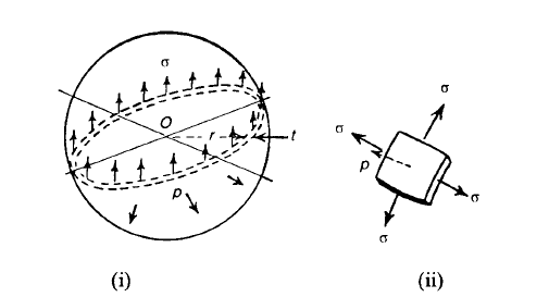
Membrane stresses in a thin spherical shell under internal pressure
This is opposed by a tensile stress  in the walls of the shell. By symmetry
  is the same at all points of the shell; for equilibrium of the hemisphere we must have,


At any point of the shell the direct stress  has the same magnitude in all directions in the plane of the surface of the shell. As p is small compared with
  , the maximum shearing stress occurs on planes at 45' to the tangent plane at any point. If the shell remains elastic, the circumference of the sphere in any diametral plane is strained an amount.

The volumetric strain of the enclosed volume of the sphere is therefore,

Equation is intended for determining membrane stresses in a perfect thin-walled spherical shell. If, however, the spherical shell is fabricated, so that its joint is weaker than the remainder of the shell, then equation takes on the following modified form,


Key Takeaway:

Cylindrical shell with hemispherical ends:
Some pressure vessels are fabricated with hemispherical ends; this has the advantage of reducing the bending stresses in the cylinder when the ends are flat. Suppose the thicknesses  and
and  of the cylindrical section and the hemispherical end, respectively are proportioned so that the radial expansion is the same for both cylinder and hemisphere; in this way we eliminate bending stresses at the junction of the two parts.
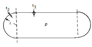
Cylindrical shell with hemispherical ends, so designed as to minimize the effects of bending stresses
The circumferential strain in the cylinder is,

The circumferential strain in the hemisphere is,

If these strains are equal, then,


Key Takeaway:

A cylinder stress is a stress distribution with rotational symmetry in mechanics, meaning that it does not vary as the stressed object is rotated around a fixed axis.
The following are examples of cylinder stress patterns:
A normal stress in the tangential (azimuth) direction is circumferential stress, also known as hoop stress.
Axial stress is a normal tension that runs parallel to the cylindrical symmetry axis.
A normal tension in directions coplanar with but perpendicular to the symmetry axis is known as radial stress.
Using a mutually perpendicular tri-axial stress system, these three main stresses—hoop, longitudinal, and radial—can be determined analytically.
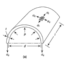
Hoop Stress (Circumferential Stress) in Cylinder
The hoop stress acts circumferentially and perpendicularly to the cylinder wall's axis and radius. The hoop stress can be estimated using the formula:

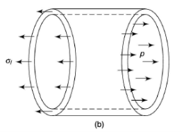
Longitudinal (Axial) Stress in Cylinder
Internal pressure provides a force along the axis of a cylinder that is closed on both ends. This force's longitudinal stress can be calculated as follows:

Hoop & Longitudinal Strain in Cylinder


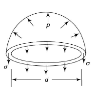
Hoop & Longitudinal Stress in Sphere
At any point of the shell the direct stress σ has the same magnitude in all directions in the plane of the surface of the shell
The two principal stresses are equal due to symmetry, Hence

The capacity of a cylinder,

Differentiating,

Dividing by  throughout,


Neglecting the effects of internal pressure,

Put, the values of  &
& 

Considering the effects of internal pressure,


Similarly for Spherical shell,
Neglecting the effects of internal pressure,
Volumetric strain =3 * hoop strain

Neglecting the effects of internal pressure,
Volumetric strain =3 * hoop strain

Key Takeaway:


Thick Cylinders
Thin shell theory is satisfactory when the thickness of the shell divided by its radius is less than 1/30. When the thickness: radius ratio of the shell is greater than this, errors start to occur, and thick shell theory should be used. Thick shells appear in the form of gun barrels, nuclear reactor pressure vessels, and deep diving submersibles.
The following convention will be used, where all the stresses and strains are assumed to be tensile and positive. At any radius, r.
 = hoop stress
 = radial stress
 = longitudinal stress
 = hoop strain
 = radial strain
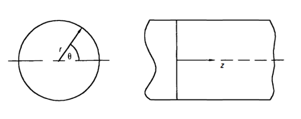
 = longitudinal strain (Assumed to be constant)
w = Radial deflection


Similarly,

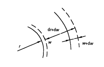
Deformation at any radius r
From the standard stress-strain relationships,


Multiplying equation 2 by r,

Differentiating equation 4 with respect to r.

Subtracting equation 3 from 5,

As,  is constant,

Differentiating above equation with respect to r.


Substituting 8 in 6,


Considering now the radial equilibrium of the shell element
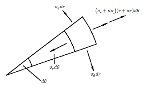
Shell Element

Neglecting higher order terms in the above, we get,

Subtracting equation 10 from 11,


Subtracting equation 12 from 14,

Or


Integrating above equation,


From equation 14

The two equations are called Lames equation. The constant A & B are obtained from boundary conditions, which are
At 
 or the pressure of fluid inside the cylinder,
At 
 or atmosphere pressure,
Key Takeaway:


Lames line:
If equations 15 and 16 are plotted with respect to a horizontal axis, the two equations appear as a single straight line.
 = internal hoop stress, which can be seen to be the maximum stress
 external hoop stress
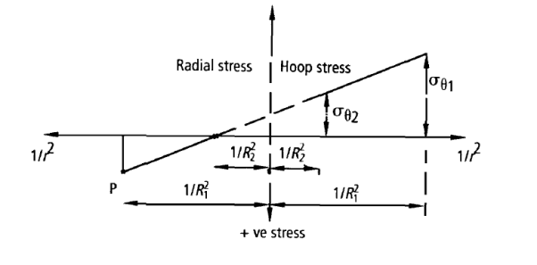
Lames line for internal pressure
Equate similar triangles,


Similarly,


Key Takeaway:


Alternative Method:
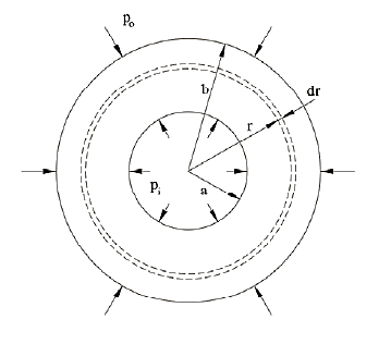
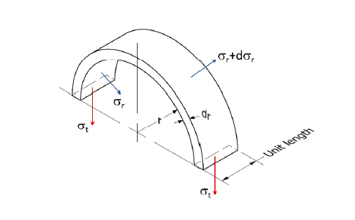
Consider a thick cylinder of external radius r1 and internal radius r2, containing a fluid under pressure ‘p’ as shown in the fig.
Let ‘L’ be the length of the cylinder.
Consider an elemental ring of radius ‘r’ and thickness ‘δr’ as shown in the above figures. Let pr and (pr+ δpr) be the intensities of radial pressures at inner and outer Consider the longitudinal section XX of the ring as shown in the fig. The bursting force is evaluated by considering the projected area,
 for the inner face and
  for the inner face and
  for the outer face.
The net bursting force, 
 ×
×
Bursting force is resisted by the hoop tensile force developing at the level of the strip

Thus, for equilibrium 


Longitudinal strain is constant. Hence, we have

Since  is compressive

Since  , E and μ are constants
  should be constant. Let it be equal to 2a. Thus


From (1), 


Integrating,

Where c is constant of integration. Let it be taken as  , where b is another constant.
Thus, 
 or radial stress,
Substituting it in equation 2, we get
Hoop stress, 

The equation (4) and (5) are known as “Lame’s Equations” for radial pressure and hoop stress at any specified point on the cylinder wall.
Thus  .
.


The equation gives the radial pressure and equation gives the hoop stress at any radius x. These two equations are called Lame's equations. The constants 'a' and 'b' are obtained from boundary conditions, which are:
(i) at x = r1, px = p0 or the pressure of fluid inside the cylinder, and
(ii) at x = r2, px = 0 or atmosphere pressure.
After knowing the values of ‘a’ and ‘b’, the hoop stress can be calculated at any radius.
The constants A and B can be determined by using boundary conditions for radial stress, which must equal the internal pressure at the inner radius and the external pressure at the outer radius (both negative).
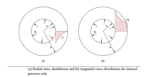
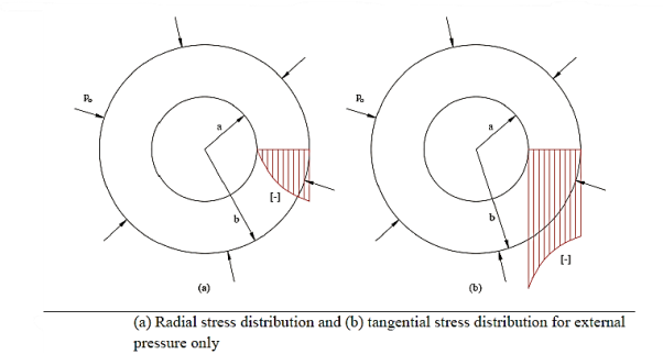
A compound tube is usually made from two cylinders of different materials where one is shrunk onto the other.
As the hoop stress is maximum at the inner radius of a thick cylindrical tube, the material at the outside of the tube is not stressed to its limit. To even out the stresses, a tube may be made of two parts, one shrunk on to the other by heating it to the required temperature. This makes the inner tube in compression and the outer tube in tension. On applying the internal pressure, a tensile hoop stress is superimposed on the compressive or shrinkage stresses of the inner tube.
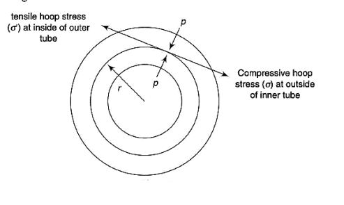
Thus initially, the inside diameter of the outer tube is smaller than the outside diameter of the inner tube. On heating the outer tube, this is increased and made equal to that. On cooling, both diameters are reduced by the same amount. The analysis is made first by calculating the stresses due to shrinkage in each component. Thus, the final diameter of the outer tube increases from the original and that of inner tube decreases. On applying the internal pressure, the stresses are calculated by assuming the two tubes as a single tube if they, are made let of the same material.
d = diameter of common surface of the inner and outer tubes
p = radial pressure at the common surface
 = compressive hoop stress at outside of inner tube
 = tensile hoop stress at the inside of the outer tube
 Youngs modulus of inner tube
 Youngs modulus of outer tube
 = Poisson’s ratio of inner tube
 = Poisson’s ratio of inner tube

 & P both are compressive and remembering that diametral strain is equal to hoop strain)

 is tensile & P being compressive,


If both tubes are of same material,

Key Takeaway:

Rotating shaft (Hub on Solid shafts):
Let, Hoop & radial stresses at radius r be,


The stresses cannot be infinite at the center of the solid shaft; therefore, b has to be zero.
d = diameter of common surface of the shaft and the hub
p = radial pressure at the common surface
 = compressive hoop stress at outside of the shaft
 = tensile hoop stress at the inside of hub
 Youngs modulus of the material of shaft
 Youngs modulus of the material of hub
 = Poisson’s ratio of the material of shaft
 = Poisson’s ratio of the material of hub
Decrease in shaft diameter = strain * diameter

 & P both are compressive and remembering that diametral strain is equal to hoop strain)

 is tensile & P being compressive,


Key Takeaway:

Rotating cylinder:
Long cylinder:
It is assumed that the longitudinal strain is constant,
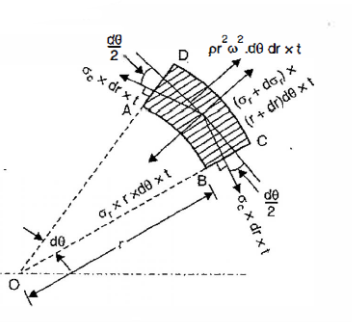
 = Circumferential stress / hoop stress
 = radial stress
 = Longitudinal stress / axial stress
 = Circumferential strain
 = radial strain
 = Longitudinal strain
Longitudinal strain,


Differentiating, (


Equation 1
Radial stress,


Equation 2
Circumferential stress,


Equation 3
Differentiating equation 3,

Equation 4
From equation 2 & 4,

Equation 5
From equation 1 & 5,

Equation 6
Equilibrium equation is the same as for disk,

Equation 7
From equation 6 & 7,

Integrating,

Equation 8
Adding equation 7 & 8

Integrating

Equation 9
Putting, value of equation 9 in 8,

Equation 10
Solid Cylinder,
As the stresses cannot be infinite at the center, therefore,

Equation 11
If R is the outside diameter,


From equation 10,

Equation 12
Maximum value. Is at the center,

Equation 13
For
From equation 12


Equation 13
Hollow cylinder:


Equation 14 & 15
From the above two equations,

From equation 14,


From equation 12,


Equation 16
 is maximum when
  or
or 
 or
or 


From equation 10,


 is maximum at inside (
 )
)


Key Takeaway:


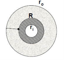
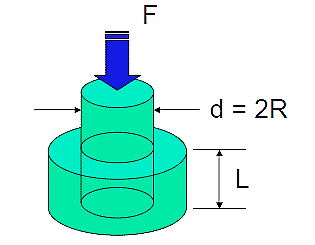
Press fittings, also known as interference fits, are similar to pressurized cylinders in that they result in radial pressure at the interface when an oversized shaft is placed in an undersized hub.
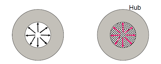
Characteristics:
• The hub is expanded, and the shaft is compressed.
• The mating surfaces have equal and opposing pressures.
• The stiffness (elasticity and geometry) of the two components determines the relative amount of compression and expansion.
• The interference introduced is equal to the total of the compression and expansion.
• The inner diameter of the hub, where the maximum tensile hoop stress occurs, is usually the crucial stress site.
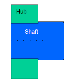
Interface pressure,
For hollow shaft,

Where  r is the RADIAL interference for hub and shaft of the same material, with modulus of elasticity, E.
For solid shaft,

If the shaft and hub are of different materials,

Once we have the pressure, we can use the cylinder equations to compute the hoop stresses at the interface.
Stress analysis:
The ID of the hub is tensile:

The OD of the shaft is compressive:

Strain analysis:
The press fit has no axial pressure, so  l = 0, and it is a biaxial stress condition.
The circumferential strain,

Which equals the radial strain (because C = 2 r.
r.
Because the radial change,

We get the increase in Inner Radius of the outer member (hub):

And the decrease in Outer Radius of the inner member (shaft):

Notes on press fit:
As a check, make sure that,

The assembly force required will be,

Where
p = the interface pressure
 = the coefficient of friction
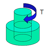
The torque capacity available is,

Where R = the interference radius.
Shrink fit:
If heating or cooling a part to achieve a shrink fit, the required radial interference is:

References:
- Strength of Materials – S.S Rattan (2nd Edition Tata McGraw Hill)
- Mechanics of Materials – Ferdinand P. Beer, E. Russell Johnston (6th Edition McGraw Hill)
- Mechanics of Materials – James M. Gere, Barry J. Goodno (Brief Edition CENGAGE Learning)
- Mechanics and Strength of Materials - Vitor Dias da Silva (1st edition Springer)
- Elements of strength of materials by Timoshenko (2nd Edition)
- Mechanics of Materials (Gere & Timoshenko 2nd edition)
- Strength of Materials (Timoshenko Volume I & II)
- Strength of Materials by Timoshenko and Young, (East West Press
- 2004 by W.H. Dornfeld- Thick-Walled Cylinders and Press Fits