Unit - 5
Curved Beams & Unsymmetrical Bending
If the curvature of a curved bar is small, i.e., radius of curvature is large compared with the dimensions of the cross-section, the analysis is like that for pure bending.
Bars of small initial curvature,
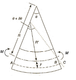
Strain in the element,


As, length of neutral axis remains constant,


As, curvature is very small and thus y is very small compared to R, thus can be neglected in denominator.

Normal stress,

As, total normal force is zero,

Neutral axis passes through the centroid,
Moment of resistance,


Strain energy of a small length  along the neutral axis under the bending moment M,

Bars of large initial curvature (Winkler -Bach Theory)
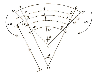
Assumptions:
- Limit of proportionality does not exceed.
- Plane transverse sections remain plane after bending.
- The material is isotropic and obeys Hooke's law.
- There are no radial strains.
- No buckling failure takes place.
Initial curvature = ABCD
Final curvature = 
Bending moment applied = M
GH = centroidal axis
PQ = any fiber at radial distance y
NE = Neutral axis
 = angles of small length at center of curvature before & after bending.


So,


The resisting moment about, an axis through the centroid,

Moments of total area about centroidal axis is zero,
i.e., 

Let,


Total force on cross-section  or
or  in circumferential direction,


As, transverse plane section sections before bending remain plain after bending, F =0

Dividing by, 

Now,


At the inside of the centroidal axis, y is negative

Position of neutral axis by 

 for different sections can be evaluated by following simplified expression.


Rectangular cross-section:
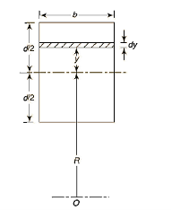
A = bd & dA = b*dy

Trapezoidal Cross-section:
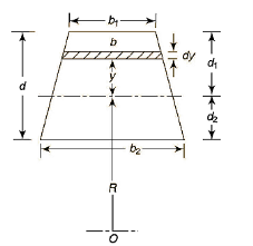


Adding & subtracting by,


In this equation,


Circular cross-sectional:
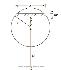


Key Takeaway:


Circular Ring:
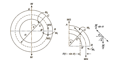


Multiplying both sides by  and integrating from 0 to

As,


Longitudinal tangential force,


So,

Multiplying by 2R

Similarly,


So,

As,


So,


Direct stress,

Total Stress,

Stress along line of action of load,


Stress on a section perpendicular to line of action of load,


Crane Hook:
A crane hook must be able to withstand greater loads. At larger loads, they are prone to failure. When a crane hook is built with various cross sections, such as circular, rectangular, and trapezoidal, the stresses created in the trapezoidal cross section are significantly lower than those caused in the other cross sections. As a result, crane hooks have trapezoidal parts.
We will be understanding this with the help of an Example:
A crane hook having a trapezoidal horizontal cross-section is 50 mm wide inside and 30 mm wide outside. Thickness of the section is 60 mm. The crane hook carries a vertical load of 20 kN whose line of action is 50 mm from the inside edge of the section. The centre of curvature is 60 mm from the inside edge. Determine the maximum tensile and compressive stresses in the section.
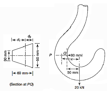
As, Trapezoidal Cross-section,


Stress at outside face (P)


Stress at inside face (Q)


Direct Stress,

Maximum Stress,
Outside edge = -57.76 + 8.33 = - 49.43 Mpa
Inside edge = 77.88 + 8.33 =86.21 Mpa
Key Takeaway:


In addition to its material and other features, the strength of a structural component is determined by the geometrical properties of its cross-section. A beam with a large cross-section, for example, will be able to withstand a bending moment more readily than one with a smaller cross-section. A cross-section of a typical structural element is depicted.
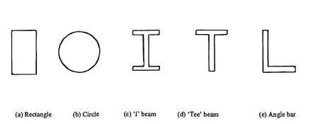
Centroid:
The position of the centroid of a cross-section is the center of the moment of area of the cross-section. If the cross-section is constructed from a homogeneous material, its centroid will lie at the same position as its center of gravity.
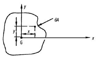
Let G denote the position of the centroid of the plane lamina. At the centroid the moment of area is zero, so that the following equations apply,

DA = elemental area of the lamina
x = horizontal distance of dA from G
y = Vertical distance of dA from G
Centroidal axes:
These are the axes that pass through the centroid.
Second moment of area (I):
The second moments of area of the lamina about the x - x and y - y axes, respectively, are given by,


From Pythagoras theorem,


Above equation is known as the perpendicular axes theorem which states that the sum of the second moments of area of two mutually perpendicular axes of a lamina is equal to the polar second moment of area about a point where these two axes cross.
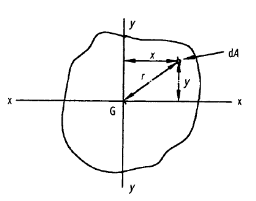
Where,
J = polar second moment of area

Parallel axes theorem:
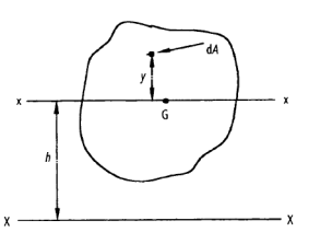
Consider a lamina where the x-x axis passes through its centroid. Suppose that  , is known and that
  , is required, where the X-X axis lies parallel to the x-x axis and at a perpendicular distance h from it.


But,


This is known as the parallel axis’s theorem, which states that the second moment of area about the X-X axis is equal to the second moment of area about the x-x axis +  , where x-x and X-X are parallel.
h = the perpendicular distance between the x-x and X-X axes.
 = the second moment of area about x-x
 = the second moment of area about X-X
Section modulus:
The maximum bending stress in a beam is calculated as,

Where y is the distance from the neutral axis to the extreme fiber,  is the centroidal moment of inertia, and M is the bending moment.
The section modulus combines the y and  terms in the bending stress equation:

Using the section modulus, the bending stress is calculated as,

The utility of the section modulus is that it characterizes the bending resistance of a cross section in a single term. This allows for optimization of a beam's cross section to resist bending by maximizing a single parameter.
The ratio I/ y where y is the farthest or the most distant point of the section from the neutral axis is called section modulus. It is denoted by Z.
Rectangle:
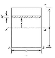

We know that the moment of inertia of the section about X-X axis,

Now moment of inertia of the whole section may be found out by integrating the above equation for the whole length of the lamina i.e., from  to
to  .
.


By, parallel axis theorem,

Section Modulus,

I-Section:
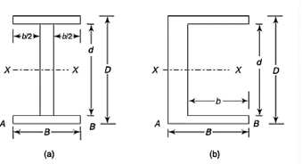


Circular section:
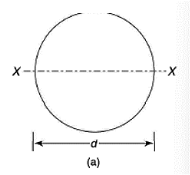


Key Takeaway:
Shape | Representation | Properties | |
Rectangle |
| Area [i   Moment of Inertia [i    
| Section Modulus[i   Radius of Gyration [in]  
|
Circle |
| Area [i   Moment of Inertia [i  

| Section Modulus[i   Radius of Gyration [in] 
|
Circular Tube |
| Area [i   Moment of inertia[i   
| Section Modulus[i   Radius of Gyration [in]   |
I-beam |
| Area   
| Section Modulus  
|
In Unsymmetrical bending, bending moments do not act in a plane of symmetry of the member or member does not possess symmetric cross-sectional area.
In case of pure bending, we have assumed that section is symmetrical about a vertical plane passing through the vertical axes of symmetry and the bending couple acts in that plane.
A vertical axis of symmetry is perpendicular to the neutral axis passing through the centroid. Owing to symmetry of such member and of the loading the member remains symmetric with respect to the vertical plane and is banned in that plane. If the vertical plane it's not a plane of symmetry the member cannot be expected to bend in that plane
For symmetrical bending the summation of moments of all the elementary forces about the vertical axis of symmetry must be zero.


Which is the necessary condition to use the bending equation derived earlier. However, this condition is found satisfied for a set of two perpendicular axis for all types of symmetric and non-symmetric sections.

The two axes for which it is zero for a section are known as principal axes or principal centroidal axes of the cross-section.
Note:

Is not Product of,

&

Thus wherever, 

In case of unsymmetrical bending, it is assumed that there is no twisting of members due to unsymmetric shear stresses it is observed that if the load is applied through a particular point known as share centre there will not be any torsion or twisting of a member.
The shear centre may lie in or outside the section if the load is not applied through the share centre there is twisting off the beam due to unbalanced movement caused by the shear force acting on the section.
For sections symmetrical about an axis the shear centre lies all the axis of symmetry for sections having to axis off symmetry the shear centre lies at the intersection of this axis and thus coincides with the centroid.
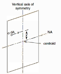
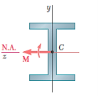
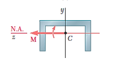
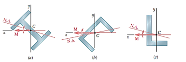
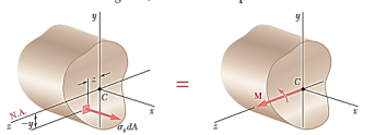


As,
From Bernoulli-Euler bending equation or Flexural Formula.

Assuming, the stresses to remain within the proportional limit of the material,

Moment about, y-axis


The  represents the product of inertia
  of the cross section with respect to the y and z axes, and will be zero if these axes are the principal centroidal axes of the cross section. We thus conclude that the neutral axis of the cross section will coincide with the axis of the couple M representing the forces acting on that section if, and only if, the couple vector M is directed along one of the principal centroidal axes of the cross section.
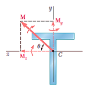


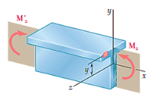

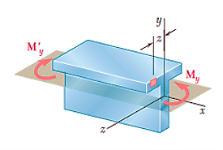


For, neutral axis,


For slope,

Determination of Principal axis:
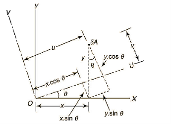
OX & OY = perpendicular axes through centroid
OU & OV = principal axes
Inclination of OU with OX be 


Product of inertia,


Key Takeaway:


Channel Section:

Net force applied on elemental area  towards left,

Total force applied on gross area of block,

This force on the block tends to slide the block towards left which is resisted by the shear force due to, complimentary shear stress in vertical plane at QT.
Net shear force at the surface = shear stress * area

Equating the two forces,


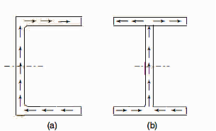

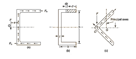
Moment of inertial,

Shear stress in elementary length,

Shear force in elementary length,

Total force in each flange,

Now, if the force F acts through the vertical axis of the web, no moments result from the vertical forces whereas clockwise moments give rise to a clockwise couple which can twist the cross-section of the channel. However, if the line of application of the vertical force F is displaced to the left at a distance e from the vertical axis of the web, the clockwise couple due to force in the flanges can be made to balance with the counter-clockwise couple to external force F and vertical force in the web,


I cross-section:
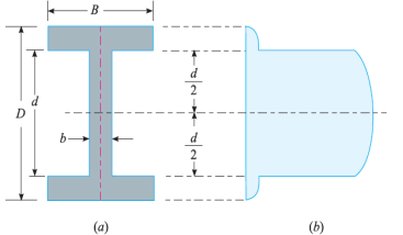
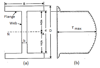
Consider a beam of an I-section as shown in Fig. (a)
Let B = Overall width of the section,
D = Overall depth of the section,
d = Depth of the web, and
b = Thickness of the web.
We know that the shear stress on a layer JK at a distance y from the neutral axis is given by,

Substituting all the values which are to be calculated by the procedure mentioned previously, we get,
- When y is greater than d/2

- When y is less than d/2

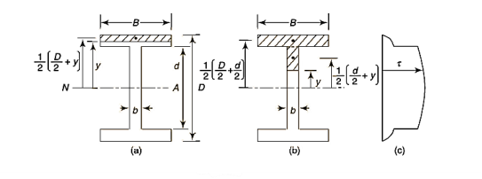

Shear stress distribution in flange,
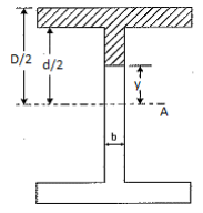
Shaded area of flange, A = 
Distance of CG of shaded area from Neutral axis,

Shear stress in flange,

For upper edge of flange,

For lower edge of flange,

Shear stress distribution in web,
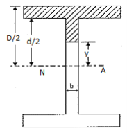


At the neutral axis, y =0, Shear stress is maximum,


At the junction of top of the web and bottom of flange,
y = d/2
Shear stress,

Example:
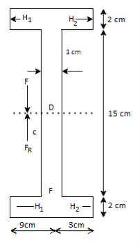


Taking moment about, D,


Key Takeaway:


References:
- Strength of Materials – S.S Rattan (2nd Edition Tata McGraw Hill)
- Mechanics of Materials – Ferdinand P. Beer, E. Russell Johnston (6th Edition McGraw Hill)
- Mechanics of Materials – James M. Gere, Barry J. Goodno (Brief Edition CENGAGE Learning)
- Mechanics and Strength of Materials - Vitor Dias da Silva (1st edition Springer)
- Elements of strength of materials by Timoshenko (2nd Edition)