Unit - 3
Spur Gears
Spur Gears:
The gears connecting two parallel and coplanar shafts are known as a spur gear.
There are two forms of tooth:
- Involute teeth profile:
An involute teeth profile is defined as the locus of a point on a straight line that rolls without slipping on the circumference of a circle. The circle on which the straight lines roll is known as the base circle.
Let A be the point on a base circle. First divide the circle into an equal number of parts, for example, Ap1=P1P2=P2P3, etc. Draw the tangents at points P1, P2, P3, etc. Cut the length equals to AP1, AP2, and AP3 on the tangents made from points P1, P2, and P3 and mark the points as A1, A2, and A3.
Join all the points, will form an involute teeth profile. For such teeth profile, normal at any point of an involute is a tangent to the base circle.
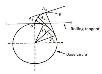
Fig. 1: Involute teeth
2. Cycloidal Teeth profile:
It is a locus of a point on the circumference of the circle that rolls without slipping on a fixed straight line. When a circle rolls without slipping on the circumference of another circle, the locus of a point on the circle is known as epicycloid. If a circle rolls without slipping inside the circumference of another circle, the locus of the point on the circle is known as hypocycloid.
Let APB is a circle inside which a circle H rolls. When rolling starts, A is the point of contact. As the circle rolls, the locus of point A gives a path ALP which is a hypocycloid. A small portion of the curve near the pitch circle is used for the flank of the tooth.
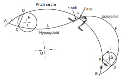
Fig. 2: Cycloidal tooth profile
Let a circle E rotates or rolls outside the pitch circle, then the locus of its point of contact form an epicycloids PFB. A small portion of the curve near the pitch circle is used for the face of the tooth.
Key Takeaways:
The gears connecting two parallel and coplanar shafts are known as a spur gear.
For such teeth profile, normal at any point of an involute is a tangent to the base circle.
- The following four systems of gear teeth are commonly used in practice:
- 14.50 composite system,
- 14.50 full depth involute system
- 200 full depth involute system, and
- 200 stub involute system
b. The 14.50 composite systems are used for general purpose gears. It is stronger but has no interchangeability. The tooth profile of this system has cycloidal curves at the top and bottom and involute curve at the middle portion.
c. The tooth profile of the 14.50 full depth involute system was developed for use with gear hobs for spur and helical gears.
d. The tooth profile of the 200 full depth involute systems may be cut by the hobs. The increase of the pressure angle from14.50 to 200 results in a stronger tooth because the tooth acting as a beam is wider at the base.
e. The 200 stub involute systems have a strong tooth to take heavy loads.
Key Takeaways:
- The tooth profile of this system has cycloidal curves at the top and bottom and involute curve at the middle portion.
- The 200 stub involute systems have a strong tooth to take heavy loads.
It is defined as the ratio of the length of the arc of contact to the circular pitch.
Contact ratio=Length of the arc of contact/p
Where p=circular pitch=πm
S.No. | Particulars | 14(1/2)0 composite or full depth involute system(m) | 200full depth involute system(m) | 200 stub involute system(m) |
1. | Addendum | 1 | 1 | 0.8 |
2. | Dedendum | 1.25 | 1.25 | 1 |
3. | Working Depth | 2 | 2 | 1.60 |
4. | Minimum tooth depth | 2.25 | 2.25 | 1.80 |
5. | Tooth Thickness | 1.5708 | 1.5708 | 1.5708 |
6. | Minimum Clearance | 0.25 | 0.25 | 0.2 |
7. | Fillet radius at root | 0.4 | 0.4 | 0.4 |
The phenomenon when the tip of a tooth undercuts the root on its mating gear is known as interference.
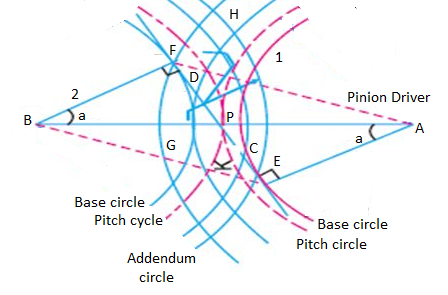
Fig. 3: Interference of gear
It is the difference between the tooth space and the tooth thickness as measured on the pitch circle. It is sometimes, a clearance or lost motion in a mechanism, which can be defined as the maximum angle or distance through which any part of the mechanical system moved in one direction without applying appreciable force to the next part of the mechanical system.
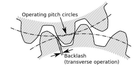
Fig. 4: Backlash
Key Takeaways:
It is the difference between the tooth space and the tooth thickness as measured on the pitch circle.
Factors on which selection of gear material depends are:
- Type of service
- Degree of the desired accuracy
- Required dimensions and weight of the drive
- Peripheral speed
- Method of manufacturing
- Allowable stress
- Wear resistance
- Shock resistance
The gear manufacturing method can be classified into major two categories:
- Forming:
It is having various other techniques like direct casting, molding, extrusion of tooth form in molten or drawing, and powered or heat softened material.
2. Machining:
It is a very common and conventional method for gear manufacturing in which the roughing and other finishing operations are involved for manufacturing.
Characteristics of forming and machining method:
The accuracy of the tooth is entirely dependent on the quality of the die or the mold and in general, it is less than can be obtained from finishing methods or we can say than of machining operations.
Following are the considerations met in the design of gear drive:
- The gear should have sufficient strength so that it will not fail under static load or dynamic loading during normal running conditions.
- The gear tooth should have to wear characteristics so that their life is satisfactory.
- The use of space and material should be economical.
- The alignments of the gear and the deflections of the shafts must be considered because they affect the performance of the gears.
- The lubrication of the gears must be satisfactory.
It is determined from an equation known as Lewis and the load-carrying ability of the toothed gear as determined by this equation gives satisfactory results.
Consider each tooth as a cantilever beam loaded by a normal load (WN)
It is resolved into two components that are tangential (WT) component and radial component (WR) acting perpendicular and parallel to the line of tooth respectively.
The tangential component (WT) induces bending stress which tends to break the tooth.
The radial component (WT) induces compressive stress of relatively small magnitude; therefore its effect on the tooth may be neglected. Hence, the bending stress is used as the basis for design calculations.
The critical or the section of maximum bending stress may be obtained by drawing a parabola through A and tangential to the tooth curves at B and C.
The tooth is larger than the parabola at every section except BC is the section of maximum stress or the critical section.
Let,
h=Length of the tooth
T= thickness of the tooth
b =width of the face
The maximum value of the bending stress at section BC is given by
σw =My/I, where, M= maximum bending moment
y=half of the thickness, I=moment of inertia about the center.
Substituting, the values for M, y, and I in the above equation, we get
σw=[(WT*h)t/2]/(bt3/12)
=(WT*h)6/bt2
Let,
t=xpc and h=kpcwhere x and k are constants
WT= σwb(x2pc2)/6kpc
The value of y in terms of the number of teeth may be expressed as follows:
y =0.124-(0.684/T), for 14.50 composite and full depth involute system.
= 0.154-(0.912/T), for 200 full depth involute system.
=0.175- (0.841/T), for 200 stub system.
Key Takeaways:
- It is having various other techniques like direct casting, molding, extrusion of tooth form in molten or drawing, and powered or heat softened material.
- The alignments of the gear and the deflections of the shafts must be considered because they affect the performance of the gears.
- The tangential component (WT) induces bending stress which tends to break the tooth.
The dynamic loads are due to the following reasons:
- Inaccuracies of tooth spacing.
- Irregularities in tooth profiles, and
- Deflections of the teeth under load.
Total dynamic load,
WD=WT+Wt
Where, WT= steady load due to transmitted torque, and
Wt= Increment load due to dynamic action
The increment load depends upon the pitch line velocity, the face width, material of the gear, and the accuracy of cut, and the tangential load.
For average conditions, the dynamic load is determined by using the following Buckingham equation,
WD=WT+21v(bc+WT)/(21v+ )
)
Where,
v= pitch line velocity
b= face width
C=A deformation or dynamic factor
Wear strength for satisfactory wear is obtained by using the following Buckingham equation, equation
Ww=DpbQK
Where W= maximum limiting load for wear in Newton
Dp= Pitch circle diameter
b= face circle, Q=Ratio factor
=2VR/(VR+1)
=2TG/(TG+TP) (For external gears)
=2VR/(VR-1)
=2TG/(TG-TP) (For internal gears)
VR=Velocity ratio, K= Load stress factor
The factors for failure of gear tooth are as follows:
- Pressure angle:
It is the angle at which the line of action makes with the common tangent to the pitch circle. It is also called the angle of obliquity. It is denoted by φ.
2. Breakage of the tooth due to static and dynamic load:
If the total repetitive load (sum of static and dynamic load) on the gear tooth is greater than the beam strength of the gear tooth, then the gear tooth will fail in bending.
3. Surface Destruction:
- Abrasive Wear:
The main cause of abrasive wear is dirt, rust, weld spatter, or metallic debris. This can be reduced by the provision of oil filters, increasing surface hardness, and the use of highly viscous oil.
b. Corrosion Wear:
The corrosion of the tooth surface is caused by corrosive elements, such as extreme pressure additives present in lubricating oil and foreign material due to external contamination. This can be reduced by the complete enclosure of the gear and selecting proper additives.
c. Pitting:
The cause of pitting is the errors in the tooth profile, surface irregularities, and misalignment of gears. It can be reduced by precise machining of gears.
d. Scoring:
The oil film between the gear teeth breaks down due to excessive surface pressure and high surface speed. This results in excessive frictional heat and overheating of the meshing teeth. This can be controlled by controlling the temperature within the permissible limit with the help of parameters like surface speed etc.
Key takeaways:
Pressure angle, Breakage of the tooth due to static and dynamic load, and Surface Destruction are the failures of the gear tooth.
Step 1: Calculation of Tangential load, which is obtained from the power transmitted and the pitch line velocity by using the following relation:
WT=(P/v)CS
Where, WT=Tangential tooth load, P= power transmitted in watts, v=πDN/60= pitch line velocity, CS= service factor, N= speed in rpm, D= Pitch circle diameter.
Step 2: Apply Lewis equation: WT=σwbpcy=σwbπmy=(σ0Cv) bπmy
Equating two values of WT= obtained from step 1 and step 2, we get the value of the module. Other values may be obtained by using the standard tooth proportions for spur gears.
Step 3: Check for wear
Calculate the tooth load, Ww=DpbQK, ifWT<Ww, the design is safe.
Key Takeaways:
For designing spur gear, the following formulae are quite important: WT=(P/v)CS,WT=(σ0Cv) bπmy and Ww=DpbQK,
The AGMA stands for American Gear Manufacturing Association. This association has developed the data for analysis and design of the gear. This is the responsible authority for the dissemination of knowledge about the design of gear.
The information given by this organization is worldwide accepted for the analysis of the gears.
The terminology and the notations for toothed gearings are also converted by the Indian Standard specifications. IS:2458 and IS: 2467 which broadly tally with the ISO recommendations.
Helical Gears
These are the spur gears in which teeth are inclined to the axis of the shaft. These are also known as spiral gears.
Helix angle: It is defined as the angle between the axis of the shaft and the centerline of the tooth taken on the pitch plane.
Transverse circular pitch (p)
The distance A1A2 in figure 2.2 is called the transverse circular pitch (p), which is measured in the plane of rotation.
Normal circular pitch (pn) The distance AC1 in figure 5 is called the normal circular pitch (pn), which is measured in a plane perpendicular to the tooth elements.
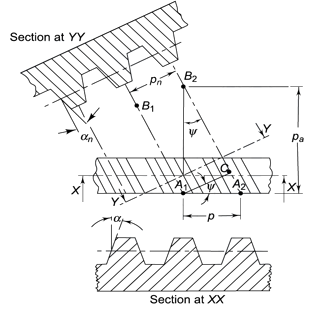
Figure 5. Tooth Relationships


From the above expression, We get

WherePn and P are normal and transverse diametral pitches respectively.
UsingP=1/m, we get
We get,
Where,
mn = normal module (mm)
m = transverse module (mm)
Axial pitch (pa) In figure 2.2in triangle A1A2B2 the distance A1B2 represents the axial pitch, which is given by the following formula.

Transverse pressure angle (α) Pressure angle in the transverse plane is known as the transverse pressure angle.
Normal-pressure angle (αn) Pressure angle in the normal plane is known as the normal pressure angle.
The relation between transverse and normal pressure angle is given by the following equation.

Pitch circle diameter (d) Pitch circle diameter of helical gear is calculated by the following relation,

Where z= number of teeth on the gear.
Central distance (a) the enter to centre distance a between the two helical gears having zl and z2 as the number of teeth is given by,

Key takeaways:
Transverse pressure angle (α) Pressure angle in the transverse plane is known as the transverse pressure angle.
Though the proportions for helical gears are not standardized, yet the following are recommended by the American Gear Manufacturing Association (AGMA).
- Pressure angle in the plane of rotation, φ=150 to 250
- Helix angle, α=200 to 450
- Addendum =0.8 m
- Dedendum=1 m
- Minimum total depth=1.8m
- Minimum clearance 0.2
- The thickness of tooth=1.5708m
- Tangential Component of forces (WT):
The direction of the tangential component for a driving gear is opposite to the direction of rotation, and that for a driven gear is the same as the direction of rotation.
2. Radial Component of force (WN):
The radial component on the pinion acts toward the center of the pinion and on the gear acts towards the center of the gear.
3. Axial Component of force (WA): The direction of the thrust component for the driven gear will be opposite to that driving gear.
WA=WTtanα
Key Takeaways:
The major components of forces of a helical gear are the Tangential Component of forces (WT), Radial Component of force (WN), and Axial Component of force (WA)
In the design of helical gears, an imaginary spur gear is considered in the plane A–A with center at O’ having a pitch circle radius of r’ and module mn. It is called a ‘formative’ or ‘virtual’ spur gear as shown in figure 2.3. The pitch circle diameter d¢ of the virtual gear is given by,

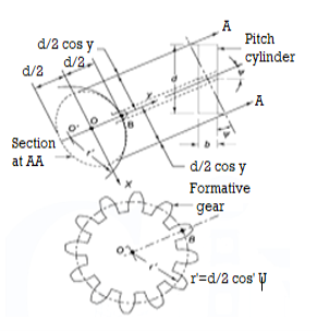
Figure 6. Formative Gear
The number of teeth z’ on this imaginary spur gear is called the virtual number of teeth. It is given by

Key Takeaways:
For finding the number of virtual teeth of a helical gear, this mentioned formula is quite important, 
Example 1 A pair of parallel helical gears consists of a 20 teeth pinion meshing with a 40 teeth gear. The helix angle is 25° and the normal pressure angle is 20°. The normal module is 3 mm.
Calculate
(i) the transverse module;
(ii) the transverse pressure angle;
(iii) the axial pitch;
(iv) the pitch circle diameters of the pinion and the gear;
(v) the center distance;
Solution: Givenzp= 20, zg = 40, mn= 3 mm, helix angle= 25°, normal pressure angle = 20°.
(i) Transverse module
Using the relation

(ii) Transverse pressure angle (α)
Using the relation

Or 
(iii) Axial pitch (pa)

(iv) Pitch circle diameters of the pinion and the gear


(v) Centre distance

Beam Strength of Helical Gear
To determine beam strength, the helical gear is considered to be equivalent to a formative spur gear, the beam strength of this formative spur gear is given by

Where,
( Sb)n=beam strength perpendicular to the tooth element,
mn = normal module
 = face width along with the tooth element
σb= bending stress on gear tooth
Y= Lewis Form factor based on virtual number of teeth
Using the relation, 
We get 
The above equation gives the beam strength of the helical gear. It is the maximum value of the tangential force that the tooth can transmit without bending failure.
Effective load on Gear Tooth
Tangential force on the helical gear tooth is given in table 2.1, which depends upon the rated power and rated speed. But during the operation, a dynamic load also acts on the gear tooth which can be considered on the following two basis-
(i) Based on the velocity factor this method of load estimation is used in the preliminary stages of gear design. The effective load in this stage is given by

Where,
Cs = service factor
Cv = velocity factor, for helical gear velocity factor, is given by the following relation

v= velocity in m/sec
(ii) Buckingham equation In the final stages of gear design, when gear dimensions are known, errors specified and the quality of gears determined, the dynamic load is calculated by an equation derived by Earle Buckingham and given by the following equation

Where Pd= incremental dynamic load, given by

v = pitch line velocity (m/s)
C = deformation factor (N/mm2)
e = sum of errors between two meshing teeth (mm)
b = face width of tooth (mm)
Pt = tangential force due to rated torque (N)
Deformation factor C is given by

Where,
k = constant depending upon the form of tooth
Ep = modulus of elasticity of pinion material (N/mm2 )
Eg = modulus of elasticity of gear material (N/mm2 )
Wear strength of helical gears
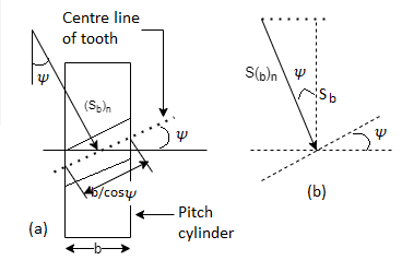
The wear strength equation of the spur gear is modified to suit helical gears. For this purpose, a pair of helical gears is considered to be equivalent to a formative pinion and a formative gear in a plane perpendicular to the tooth element. In the case of spur gears wear strength is given by

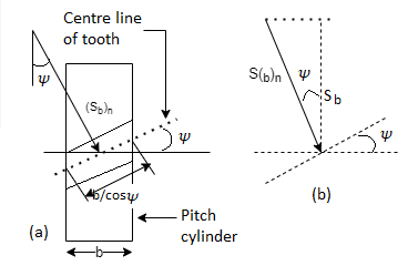
Referring to Fig.
Sw = (Sw)n = wear strength perpendicular to the tooth element
 = face width along with the tooth element
 = pitch circle diameter of the formative pinion.
Using above relations we get

The component of (Sw)n in the plane of rotation is denoted by Sw. Therefore,

Which gives,

Where
Q= ratio factor, given by

Zp= actual number of teeth on the pinion
Zg= actual number of teeth on the gear
K= Load stress factor, given by

σc = surface endurance strength (N/mm2)
Ep, Eg = moduli of elasticity of materials for pinion and gear (N/mm2)
To design the gear

Or 
Where, fs= factor of safety
Key takeaway:
The below-mentioned formula is important for calculating the beam strength of the helical gear.

Wear strength of helical gear is given by:

Example A pair of parallel helical gears consists of a 20 teeth pinion meshing with a 100 teeth gear. The pinion rotates at 720 rpm. The normal pressure angle is 20°, while the helix angle is 25°. The face width is 40 mm and the normal module is 4 mm. The pinion as well as the gear is made of steel 4OC8 (Sut = 600 N/mm2) and heat-treated to a surface hardness of 300 BHN. The service factor and the factor of safety are 1.5 and 2 respectively. Assume that the velocity factor accounts for the dynamic load and calculate the power transmitting capacity of gears.
Solution: Given np= 720 rpm, zp = 20, zg = 100, mn = 4 mm, b = 40 mm, ψ = 25°, αn = 20°
Sut = 600 N/mm2 , BHN = 300, Cs = 1.5, fs = 2, Y= 0.3475
(I) Beam strength


(II) Wear strength


Since wear strength is lower than beam strength, pitting is the criterion of failure.
(III) Tangential force due to rated torque


(IV) Power transmitting capacity of gears

Dynamic tooth load can be calculated as follows,
WD=WT+[21v(bC cos2α+ WT)cosα]/[21v+
The procedure for designing helical gear:
Step 1: Calculate tangential tooth load: Calculate the tangential tooth load from the power transmitted and pitch line velocity as given, WT=(P/v)Cs
Step 2: Find Virtual Number of Teeth: Find the virtual number of teeth on the wheel by using the equation, TE=T/ (cos3α).
Based on a virtual number of teeth, find the Lewis form factor and decide the weaker wheel.
Step 3: Apply for the Lewis equation,=(σ0*Cv)bπmy’
Step 4: Find the maximum wear strength:Ww=DpbQK/cos2α
Key Takeaways
These are the basic required formula for designing a helical gear, WT=(P/v)Cs, (σ0*Cv)bπmy’ andWw=DpbQK/cos2α
Bevel gears are gears wherein the axes of the 2 shafts intersect and the teeth-bearing faces of the gears themselves are conically shaped.
Bevel gears are most usually hooked up on shafts which might be ninety levels apart, however may be designed to paintings at different angles as well.
The pitch floor of bevel gears is a cone. Two crucial principles in gearing are pitch floor and pitch perspective.
The pitch floor of a tools is the imaginary toothless floor which you might have through averaging out the peaks and valleys of the character tooth.
The pitch floor of a regular tools is the form of a cylinder. The pitch perspective of a tools is the perspective among the face of the pitch floor and the axis. The maximum acquainted styles of bevel gears have pitch angles of much less than ninety levels and consequently are cone-shaped. This sort of bevel tools is known as outside due to the fact the tools tooth factor outward.
The pitch surfaces of meshed outside bevel gears are coaxial with the tools shafts; the apexes of the 2 surfaces are on the factor of intersection of the shaft axes. The use of a true bevel tools has even more significance for the reliability of the axle than another spare part.
Bevel gears which have pitch angles of more than 90 levels have tooth that factor inward and are known as inner bevel gears. Bevel gears which have pitch angles of precisely ninety levels have tooth that factor outward parallel with the axis and resemble the factors on a crown. That's why this sort of bevel tools is known as a crown tools.
Bevel gears are categorized in different sorts in keeping with geometry:
Straight bevel gears have conical pitch floor and tooth are instantly and tapering closer to apex. Spiral bevel gears have curved tooth at a perspective permitting teeth touch to be slow and smooth.
Zero bevel gears are very much like a bevel tools, however the tooth are curved: the ends of every teeth are coplanar with the axis, however the centre of every teeth is swept circumferentially across the tools.
Zero bevel gears may be concept of as spiral bevel gears, which additionally have curved tooth, however with a spiral perspective of zero, so the ends of the tooth align with the axis.
Hypoid bevel gears are much like spiral bevel, however the pitch surfaces are hyperbolic and now no longer conical. The pinion may be offset above or under the tools centre, consequently permitting large pinion diameter, longer life, and smoother mesh. If the bevelled floor is made parallel with the axis of rotation, this configuration resembles a malicious program drive. Hypoid gears had been extensively utilized in car rear axles.
Key Takeaways:
This sort of bevel tools is known as outside due to the fact the tools tooth factor outward.
That's why this sort of bevel tools is known as a crown tools.
Bevel Gears:
The bevel gears can be categorised relying upon the angles among the shafts and the pitch surfaces.
Classification:
The bevel gears can be categorised into the subsequent types, relying upon the angles among the shafts and the pitch surfaces.
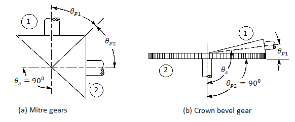
1. Mitre gears.
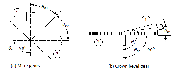
When same bevel gears (having same tooth and same pitch angles) join shafts whose axes intersect at proper perspective, as proven in Fig. (a), then they're called mitre gears.
2. Angular bevel gears.
When the bevel gears join shafts whose axes intersect at a perspective apart from a proper perspective, then they're called angular bevel gears.
3. Crown bevel gears.
When the bevel gears join shafts whose axes intersect at an perspective extra than a proper perspective and one of the bevel gears has a pitch perspective of 90º, then it's miles called a crown equipment. The crown equipment corresponds to a rack in spur gearing, as proven in Fig.b).
4. Internal bevel gears.
When the tooth at the bevel equipment are reduce at the internal of the pitch cone, then they're called inner bevel gears.
After the clean is installed, use a disk module cutter to mill the enamel groove to the overall depth; on the equal time, the cutter must in shape the module of the small radius of the equipment being milled. All equipment tooth are milled on this way. As for indexing, use the indexing head with inside the normal way
Applications:
- There are many mechanical transmission techniques used on diverse machines, the maximum essential ones are belt transmission, chain transmission, friction wheel transmission, equipment transmission and ribbon nut transmission.
- Among them, equipment transmission typically approach that one shaft can power every other shaft to rotate whilst it rotates; or it could extrude the rotary movement of 1 shaft to linear movement.
- Its fundamental traits are: the tooth are tightly meshed with every different, and the torque transmitted is tons large than that of belt and chain transmission; its transmission performance is likewise better than that of different mechanical transmissions; Keep the velocity ratio among the 2 shafts unchanged.
- There are many kinds of gears, typically divided into cylindrical gears, conical gears and computer virus gears in line with the form of the enamel surface.
- Commonly used spur gears and helical gears are cylindrical gears, that are used to power the rotation motion of together parallel shafts, and the bevel equipment (conical equipment) is used to power the rotation motion of the intersecting shafts. When the tooth of a couple of bevel gears mesh with the transmission, the scenario could be very just like the transmission of semi-conical friction wheels
- However, if the pushed pressure of the pushed shaft is more than the friction among the 2 wheels with inside the transmission of the friction wheel, the 2 wheels will slip, or maybe a pushed wheel can't be pushed.
Worm Gears:
Types:
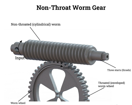
Non-Throat
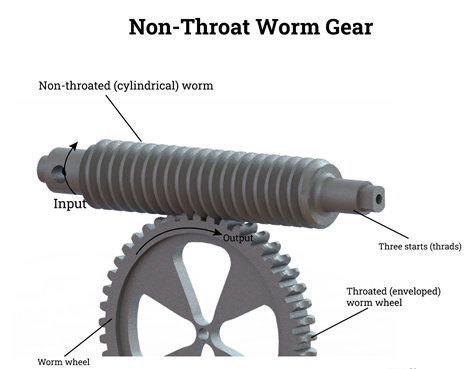
Non-throat computer virus gears do now no longer have a throat or groove machined across the computer virus or computer virus wheel and are helical gears with a directly computer virus. Tooth touch is at an unmarried factor at the transferring power and each gears are non-throated. Having an unmarried rotating factor method the tools has excessive put on and tear. Non-throated computer virus gears are designed to address small masses and are clean to make.
Single Throated
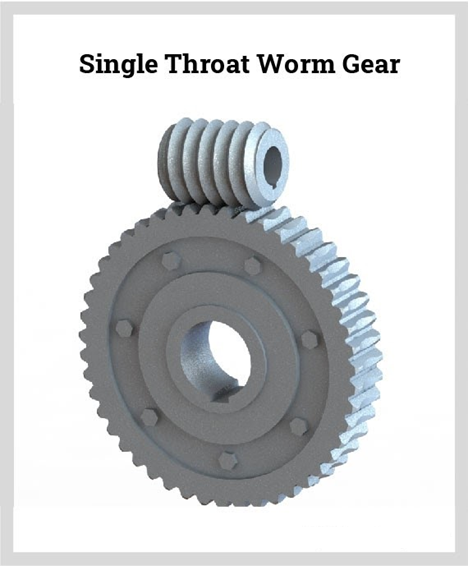
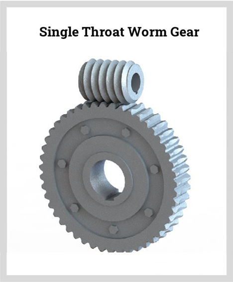
An unmarried throated computer virus tools has incarnate helical enamel designed across the computer virus for a touch line. This sort of computer virus tools can resist better strength without extra put on. In this sort of computer virus tools, handiest one set of threads at the computer virus make touch with the computer virus wheel. Due to the reality that there may be unmarried touch, which produces widespread friction, the computer virus needs to be an awful lot tougher and more potent than the wheel
Double Throat
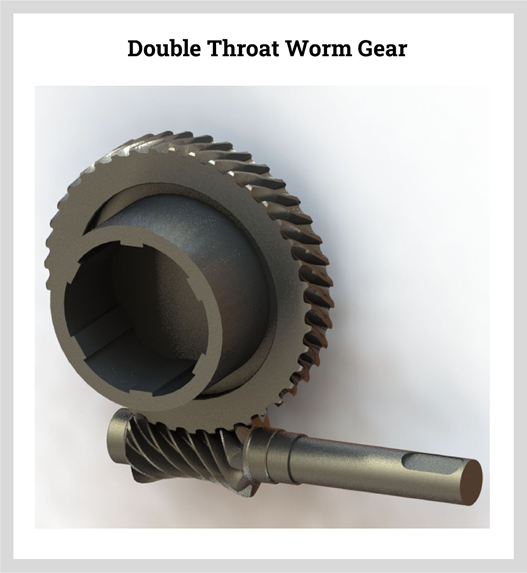
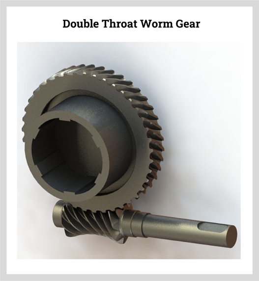
The distinction among unmarried throat computer virus gears and double throat sorts is their form. Double throat computer virus gears are concave at the tools and computer virus screw. The enamel of the tools and the form of the computer virus threads are designed to boom the touch among the wheel and computer virus. Double throat computer virus gears are capable of manage excessive masses. The layout of the double throat gives the tightest connection among the computer virus and the tools.
Applications:
Worm gears may be visible in numerous mechanisms and devices. They are used inside big system in addition to in matters with inside the home. In their purest form, computer virus gears are seen with inside the tuning mechanism of an acoustic guitar.
Lifts
Due to their compressed length and non-reversible characteristics, computer virus gears are typically determined with inside the tool used to paintings lifts. This type of tools works as a secondary braking device because the strain cannot transmit movement again thru the computer virus/hoist.
Conveyor Belts and Security Gates
As general computer virus drives can flip in a single path, they'll now no longer flow backwards whilst they may be fixed and now no longer being used. This suggests that computer virus drives are best for use on conveyor belts. They are moreover used on digital protection gates.
One computer virus power is used to open the gate, and one is used to shut it. This suggests that the gate may be secured in every path and cannot be driven open. While computer virus gears are extraordinarily beneficial, they want to be of excessive first-class to paintings effectively. At Premium Transmission, we offer top notch enterprise gearbox and computer virus gears for all varieties of uses.
Key Takeaways:
- The bevel gears can be categorised into the subsequent types, relying upon the angles among the shafts and the pitch surfaces.
- As for indexing, use the indexing head with inside the normal way
- The layout of the double throat gives the tightest connection among the computer virus and the tools.
- In their purest form, computer virus gears are seen with inside the tuning mechanism of an acoustic guitar.
References:
1. Mechanical Engineering Design, 9e – Joseph E. Shigely, McGraw Hill Education.
2. Machine Design‐Maleev and Hartman, CBS Publishers.
3. Design of Machine Design‐M.F. Spott, Pearson Education.
4. Elements of Machine Component Design, Juvinal&Marshek, John Wiley & Sons.
5. Machine design, Robert L. Norton, Pearson Education
Unit - 3
Spur Gears
Unit - 3
Spur Gears
Spur Gears:
The gears connecting two parallel and coplanar shafts are known as a spur gear.
There are two forms of tooth:
- Involute teeth profile:
An involute teeth profile is defined as the locus of a point on a straight line that rolls without slipping on the circumference of a circle. The circle on which the straight lines roll is known as the base circle.
Let A be the point on a base circle. First divide the circle into an equal number of parts, for example, Ap1=P1P2=P2P3, etc. Draw the tangents at points P1, P2, P3, etc. Cut the length equals to AP1, AP2, and AP3 on the tangents made from points P1, P2, and P3 and mark the points as A1, A2, and A3.
Join all the points, will form an involute teeth profile. For such teeth profile, normal at any point of an involute is a tangent to the base circle.
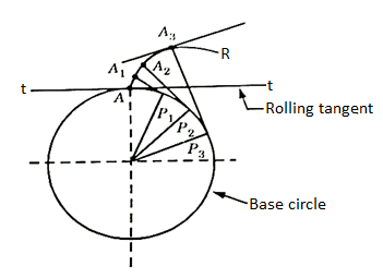
Fig. 1: Involute teeth
2. Cycloidal Teeth profile:
It is a locus of a point on the circumference of the circle that rolls without slipping on a fixed straight line. When a circle rolls without slipping on the circumference of another circle, the locus of a point on the circle is known as epicycloid. If a circle rolls without slipping inside the circumference of another circle, the locus of the point on the circle is known as hypocycloid.
Let APB is a circle inside which a circle H rolls. When rolling starts, A is the point of contact. As the circle rolls, the locus of point A gives a path ALP which is a hypocycloid. A small portion of the curve near the pitch circle is used for the flank of the tooth.
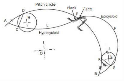
Fig. 2: Cycloidal tooth profile
Let a circle E rotates or rolls outside the pitch circle, then the locus of its point of contact form an epicycloids PFB. A small portion of the curve near the pitch circle is used for the face of the tooth.
Key Takeaways:
The gears connecting two parallel and coplanar shafts are known as a spur gear.
For such teeth profile, normal at any point of an involute is a tangent to the base circle.
- The following four systems of gear teeth are commonly used in practice:
- 14.50 composite system,
- 14.50 full depth involute system
- 200 full depth involute system, and
- 200 stub involute system
b. The 14.50 composite systems are used for general purpose gears. It is stronger but has no interchangeability. The tooth profile of this system has cycloidal curves at the top and bottom and involute curve at the middle portion.
c. The tooth profile of the 14.50 full depth involute system was developed for use with gear hobs for spur and helical gears.
d. The tooth profile of the 200 full depth involute systems may be cut by the hobs. The increase of the pressure angle from14.50 to 200 results in a stronger tooth because the tooth acting as a beam is wider at the base.
e. The 200 stub involute systems have a strong tooth to take heavy loads.
Key Takeaways:
- The tooth profile of this system has cycloidal curves at the top and bottom and involute curve at the middle portion.
- The 200 stub involute systems have a strong tooth to take heavy loads.
It is defined as the ratio of the length of the arc of contact to the circular pitch.
Contact ratio=Length of the arc of contact/p
Where p=circular pitch=πm
S.No. | Particulars | 14(1/2)0 composite or full depth involute system(m) | 200full depth involute system(m) | 200 stub involute system(m) |
1. | Addendum | 1 | 1 | 0.8 |
2. | Dedendum | 1.25 | 1.25 | 1 |
3. | Working Depth | 2 | 2 | 1.60 |
4. | Minimum tooth depth | 2.25 | 2.25 | 1.80 |
5. | Tooth Thickness | 1.5708 | 1.5708 | 1.5708 |
6. | Minimum Clearance | 0.25 | 0.25 | 0.2 |
7. | Fillet radius at root | 0.4 | 0.4 | 0.4 |
The phenomenon when the tip of a tooth undercuts the root on its mating gear is known as interference.
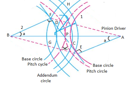
Fig. 3: Interference of gear
It is the difference between the tooth space and the tooth thickness as measured on the pitch circle. It is sometimes, a clearance or lost motion in a mechanism, which can be defined as the maximum angle or distance through which any part of the mechanical system moved in one direction without applying appreciable force to the next part of the mechanical system.
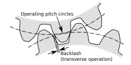
Fig. 4: Backlash
Key Takeaways:
It is the difference between the tooth space and the tooth thickness as measured on the pitch circle.
Factors on which selection of gear material depends are:
- Type of service
- Degree of the desired accuracy
- Required dimensions and weight of the drive
- Peripheral speed
- Method of manufacturing
- Allowable stress
- Wear resistance
- Shock resistance
The gear manufacturing method can be classified into major two categories:
- Forming:
It is having various other techniques like direct casting, molding, extrusion of tooth form in molten or drawing, and powered or heat softened material.
2. Machining:
It is a very common and conventional method for gear manufacturing in which the roughing and other finishing operations are involved for manufacturing.
Characteristics of forming and machining method:
The accuracy of the tooth is entirely dependent on the quality of the die or the mold and in general, it is less than can be obtained from finishing methods or we can say than of machining operations.
Following are the considerations met in the design of gear drive:
- The gear should have sufficient strength so that it will not fail under static load or dynamic loading during normal running conditions.
- The gear tooth should have to wear characteristics so that their life is satisfactory.
- The use of space and material should be economical.
- The alignments of the gear and the deflections of the shafts must be considered because they affect the performance of the gears.
- The lubrication of the gears must be satisfactory.
It is determined from an equation known as Lewis and the load-carrying ability of the toothed gear as determined by this equation gives satisfactory results.
Consider each tooth as a cantilever beam loaded by a normal load (WN)
It is resolved into two components that are tangential (WT) component and radial component (WR) acting perpendicular and parallel to the line of tooth respectively.
The tangential component (WT) induces bending stress which tends to break the tooth.
The radial component (WT) induces compressive stress of relatively small magnitude; therefore its effect on the tooth may be neglected. Hence, the bending stress is used as the basis for design calculations.
The critical or the section of maximum bending stress may be obtained by drawing a parabola through A and tangential to the tooth curves at B and C.
The tooth is larger than the parabola at every section except BC is the section of maximum stress or the critical section.
Let,
h=Length of the tooth
T= thickness of the tooth
b =width of the face
The maximum value of the bending stress at section BC is given by
σw =My/I, where, M= maximum bending moment
y=half of the thickness, I=moment of inertia about the center.
Substituting, the values for M, y, and I in the above equation, we get
σw=[(WT*h)t/2]/(bt3/12)
=(WT*h)6/bt2
Let,
t=xpc and h=kpcwhere x and k are constants
WT= σwb(x2pc2)/6kpc
The value of y in terms of the number of teeth may be expressed as follows:
y =0.124-(0.684/T), for 14.50 composite and full depth involute system.
= 0.154-(0.912/T), for 200 full depth involute system.
=0.175- (0.841/T), for 200 stub system.
Key Takeaways:
- It is having various other techniques like direct casting, molding, extrusion of tooth form in molten or drawing, and powered or heat softened material.
- The alignments of the gear and the deflections of the shafts must be considered because they affect the performance of the gears.
- The tangential component (WT) induces bending stress which tends to break the tooth.
The dynamic loads are due to the following reasons:
- Inaccuracies of tooth spacing.
- Irregularities in tooth profiles, and
- Deflections of the teeth under load.
Total dynamic load,
WD=WT+Wt
Where, WT= steady load due to transmitted torque, and
Wt= Increment load due to dynamic action
The increment load depends upon the pitch line velocity, the face width, material of the gear, and the accuracy of cut, and the tangential load.
For average conditions, the dynamic load is determined by using the following Buckingham equation,
WD=WT+21v(bc+WT)/(21v+ )
)
Where,
v= pitch line velocity
b= face width
C=A deformation or dynamic factor
Wear strength for satisfactory wear is obtained by using the following Buckingham equation, equation
Ww=DpbQK
Where W= maximum limiting load for wear in Newton
Dp= Pitch circle diameter
b= face circle, Q=Ratio factor
=2VR/(VR+1)
=2TG/(TG+TP) (For external gears)
=2VR/(VR-1)
=2TG/(TG-TP) (For internal gears)
VR=Velocity ratio, K= Load stress factor
The factors for failure of gear tooth are as follows:
- Pressure angle:
It is the angle at which the line of action makes with the common tangent to the pitch circle. It is also called the angle of obliquity. It is denoted by φ.
2. Breakage of the tooth due to static and dynamic load:
If the total repetitive load (sum of static and dynamic load) on the gear tooth is greater than the beam strength of the gear tooth, then the gear tooth will fail in bending.
3. Surface Destruction:
- Abrasive Wear:
The main cause of abrasive wear is dirt, rust, weld spatter, or metallic debris. This can be reduced by the provision of oil filters, increasing surface hardness, and the use of highly viscous oil.
b. Corrosion Wear:
The corrosion of the tooth surface is caused by corrosive elements, such as extreme pressure additives present in lubricating oil and foreign material due to external contamination. This can be reduced by the complete enclosure of the gear and selecting proper additives.
c. Pitting:
The cause of pitting is the errors in the tooth profile, surface irregularities, and misalignment of gears. It can be reduced by precise machining of gears.
d. Scoring:
The oil film between the gear teeth breaks down due to excessive surface pressure and high surface speed. This results in excessive frictional heat and overheating of the meshing teeth. This can be controlled by controlling the temperature within the permissible limit with the help of parameters like surface speed etc.
Key takeaways:
Pressure angle, Breakage of the tooth due to static and dynamic load, and Surface Destruction are the failures of the gear tooth.
Step 1: Calculation of Tangential load, which is obtained from the power transmitted and the pitch line velocity by using the following relation:
WT=(P/v)CS
Where, WT=Tangential tooth load, P= power transmitted in watts, v=πDN/60= pitch line velocity, CS= service factor, N= speed in rpm, D= Pitch circle diameter.
Step 2: Apply Lewis equation: WT=σwbpcy=σwbπmy=(σ0Cv) bπmy
Equating two values of WT= obtained from step 1 and step 2, we get the value of the module. Other values may be obtained by using the standard tooth proportions for spur gears.
Step 3: Check for wear
Calculate the tooth load, Ww=DpbQK, ifWT<Ww, the design is safe.
Key Takeaways:
For designing spur gear, the following formulae are quite important: WT=(P/v)CS,WT=(σ0Cv) bπmy and Ww=DpbQK,
The AGMA stands for American Gear Manufacturing Association. This association has developed the data for analysis and design of the gear. This is the responsible authority for the dissemination of knowledge about the design of gear.
The information given by this organization is worldwide accepted for the analysis of the gears.
The terminology and the notations for toothed gearings are also converted by the Indian Standard specifications. IS:2458 and IS: 2467 which broadly tally with the ISO recommendations.
Helical Gears
These are the spur gears in which teeth are inclined to the axis of the shaft. These are also known as spiral gears.
Helix angle: It is defined as the angle between the axis of the shaft and the centerline of the tooth taken on the pitch plane.
Transverse circular pitch (p)
The distance A1A2 in figure 2.2 is called the transverse circular pitch (p), which is measured in the plane of rotation.
Normal circular pitch (pn) The distance AC1 in figure 5 is called the normal circular pitch (pn), which is measured in a plane perpendicular to the tooth elements.
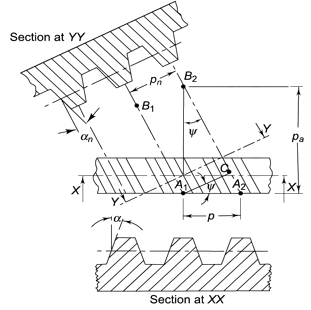
Figure 5. Tooth Relationships


From the above expression, We get

WherePn and P are normal and transverse diametral pitches respectively.
UsingP=1/m, we get
We get,
Where,
mn = normal module (mm)
m = transverse module (mm)
Axial pitch (pa) In figure 2.2in triangle A1A2B2 the distance A1B2 represents the axial pitch, which is given by the following formula.

Transverse pressure angle (α) Pressure angle in the transverse plane is known as the transverse pressure angle.
Normal-pressure angle (αn) Pressure angle in the normal plane is known as the normal pressure angle.
The relation between transverse and normal pressure angle is given by the following equation.

Pitch circle diameter (d) Pitch circle diameter of helical gear is calculated by the following relation,

Where z= number of teeth on the gear.
Central distance (a) the enter to centre distance a between the two helical gears having zl and z2 as the number of teeth is given by,

Key takeaways:
Transverse pressure angle (α) Pressure angle in the transverse plane is known as the transverse pressure angle.
Though the proportions for helical gears are not standardized, yet the following are recommended by the American Gear Manufacturing Association (AGMA).
- Pressure angle in the plane of rotation, φ=150 to 250
- Helix angle, α=200 to 450
- Addendum =0.8 m
- Dedendum=1 m
- Minimum total depth=1.8m
- Minimum clearance 0.2
- The thickness of tooth=1.5708m
- Tangential Component of forces (WT):
The direction of the tangential component for a driving gear is opposite to the direction of rotation, and that for a driven gear is the same as the direction of rotation.
2. Radial Component of force (WN):
The radial component on the pinion acts toward the center of the pinion and on the gear acts towards the center of the gear.
3. Axial Component of force (WA): The direction of the thrust component for the driven gear will be opposite to that driving gear.
WA=WTtanα
Key Takeaways:
The major components of forces of a helical gear are the Tangential Component of forces (WT), Radial Component of force (WN), and Axial Component of force (WA)
In the design of helical gears, an imaginary spur gear is considered in the plane A–A with center at O’ having a pitch circle radius of r’ and module mn. It is called a ‘formative’ or ‘virtual’ spur gear as shown in figure 2.3. The pitch circle diameter d¢ of the virtual gear is given by,

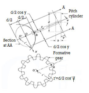
Figure 6. Formative Gear
The number of teeth z’ on this imaginary spur gear is called the virtual number of teeth. It is given by

Key Takeaways:
For finding the number of virtual teeth of a helical gear, this mentioned formula is quite important, 
Example 1 A pair of parallel helical gears consists of a 20 teeth pinion meshing with a 40 teeth gear. The helix angle is 25° and the normal pressure angle is 20°. The normal module is 3 mm.
Calculate
(i) the transverse module;
(ii) the transverse pressure angle;
(iii) the axial pitch;
(iv) the pitch circle diameters of the pinion and the gear;
(v) the center distance;
Solution: Givenzp= 20, zg = 40, mn= 3 mm, helix angle= 25°, normal pressure angle = 20°.
(i) Transverse module
Using the relation

(ii) Transverse pressure angle (α)
Using the relation

Or 
(iii) Axial pitch (pa)

(iv) Pitch circle diameters of the pinion and the gear


(v) Centre distance

Beam Strength of Helical Gear
To determine beam strength, the helical gear is considered to be equivalent to a formative spur gear, the beam strength of this formative spur gear is given by

Where,
( Sb)n=beam strength perpendicular to the tooth element,
mn = normal module
 = face width along with the tooth element
σb= bending stress on gear tooth
Y= Lewis Form factor based on virtual number of teeth
Using the relation, 
We get 
The above equation gives the beam strength of the helical gear. It is the maximum value of the tangential force that the tooth can transmit without bending failure.
Effective load on Gear Tooth
Tangential force on the helical gear tooth is given in table 2.1, which depends upon the rated power and rated speed. But during the operation, a dynamic load also acts on the gear tooth which can be considered on the following two basis-
(i) Based on the velocity factor this method of load estimation is used in the preliminary stages of gear design. The effective load in this stage is given by

Where,
Cs = service factor
Cv = velocity factor, for helical gear velocity factor, is given by the following relation

v= velocity in m/sec
(ii) Buckingham equation In the final stages of gear design, when gear dimensions are known, errors specified and the quality of gears determined, the dynamic load is calculated by an equation derived by Earle Buckingham and given by the following equation

Where Pd= incremental dynamic load, given by

v = pitch line velocity (m/s)
C = deformation factor (N/mm2)
e = sum of errors between two meshing teeth (mm)
b = face width of tooth (mm)
Pt = tangential force due to rated torque (N)
Deformation factor C is given by

Where,
k = constant depending upon the form of tooth
Ep = modulus of elasticity of pinion material (N/mm2 )
Eg = modulus of elasticity of gear material (N/mm2 )
Wear strength of helical gears
The wear strength equation of the spur gear is modified to suit helical gears. For this purpose, a pair of helical gears is considered to be equivalent to a formative pinion and a formative gear in a plane perpendicular to the tooth element. In the case of spur gears wear strength is given by

Referring to Fig.
Sw = (Sw)n = wear strength perpendicular to the tooth element
 = face width along with the tooth element
 = pitch circle diameter of the formative pinion.
Using above relations we get

The component of (Sw)n in the plane of rotation is denoted by Sw. Therefore,

Which gives,

Where
Q= ratio factor, given by

Zp= actual number of teeth on the pinion
Zg= actual number of teeth on the gear
K= Load stress factor, given by

σc = surface endurance strength (N/mm2)
Ep, Eg = moduli of elasticity of materials for pinion and gear (N/mm2)
To design the gear

Or 
Where, fs= factor of safety
Key takeaway:
The below-mentioned formula is important for calculating the beam strength of the helical gear.

Wear strength of helical gear is given by:

Example A pair of parallel helical gears consists of a 20 teeth pinion meshing with a 100 teeth gear. The pinion rotates at 720 rpm. The normal pressure angle is 20°, while the helix angle is 25°. The face width is 40 mm and the normal module is 4 mm. The pinion as well as the gear is made of steel 4OC8 (Sut = 600 N/mm2) and heat-treated to a surface hardness of 300 BHN. The service factor and the factor of safety are 1.5 and 2 respectively. Assume that the velocity factor accounts for the dynamic load and calculate the power transmitting capacity of gears.
Solution: Given np= 720 rpm, zp = 20, zg = 100, mn = 4 mm, b = 40 mm, ψ = 25°, αn = 20°
Sut = 600 N/mm2 , BHN = 300, Cs = 1.5, fs = 2, Y= 0.3475
(I) Beam strength


(II) Wear strength


Since wear strength is lower than beam strength, pitting is the criterion of failure.
(III) Tangential force due to rated torque


(IV) Power transmitting capacity of gears

Dynamic tooth load can be calculated as follows,
WD=WT+[21v(bC cos2α+ WT)cosα]/[21v+
The procedure for designing helical gear:
Step 1: Calculate tangential tooth load: Calculate the tangential tooth load from the power transmitted and pitch line velocity as given, WT=(P/v)Cs
Step 2: Find Virtual Number of Teeth: Find the virtual number of teeth on the wheel by using the equation, TE=T/ (cos3α).
Based on a virtual number of teeth, find the Lewis form factor and decide the weaker wheel.
Step 3: Apply for the Lewis equation,=(σ0*Cv)bπmy’
Step 4: Find the maximum wear strength:Ww=DpbQK/cos2α
Key Takeaways
These are the basic required formula for designing a helical gear, WT=(P/v)Cs, (σ0*Cv)bπmy’ andWw=DpbQK/cos2α
Bevel gears are gears wherein the axes of the 2 shafts intersect and the teeth-bearing faces of the gears themselves are conically shaped.
Bevel gears are most usually hooked up on shafts which might be ninety levels apart, however may be designed to paintings at different angles as well.
The pitch floor of bevel gears is a cone. Two crucial principles in gearing are pitch floor and pitch perspective.
The pitch floor of a tools is the imaginary toothless floor which you might have through averaging out the peaks and valleys of the character tooth.
The pitch floor of a regular tools is the form of a cylinder. The pitch perspective of a tools is the perspective among the face of the pitch floor and the axis. The maximum acquainted styles of bevel gears have pitch angles of much less than ninety levels and consequently are cone-shaped. This sort of bevel tools is known as outside due to the fact the tools tooth factor outward.
The pitch surfaces of meshed outside bevel gears are coaxial with the tools shafts; the apexes of the 2 surfaces are on the factor of intersection of the shaft axes. The use of a true bevel tools has even more significance for the reliability of the axle than another spare part.
Bevel gears which have pitch angles of more than 90 levels have tooth that factor inward and are known as inner bevel gears. Bevel gears which have pitch angles of precisely ninety levels have tooth that factor outward parallel with the axis and resemble the factors on a crown. That's why this sort of bevel tools is known as a crown tools.
Bevel gears are categorized in different sorts in keeping with geometry:
Straight bevel gears have conical pitch floor and tooth are instantly and tapering closer to apex. Spiral bevel gears have curved tooth at a perspective permitting teeth touch to be slow and smooth.
Zero bevel gears are very much like a bevel tools, however the tooth are curved: the ends of every teeth are coplanar with the axis, however the centre of every teeth is swept circumferentially across the tools.
Zero bevel gears may be concept of as spiral bevel gears, which additionally have curved tooth, however with a spiral perspective of zero, so the ends of the tooth align with the axis.
Hypoid bevel gears are much like spiral bevel, however the pitch surfaces are hyperbolic and now no longer conical. The pinion may be offset above or under the tools centre, consequently permitting large pinion diameter, longer life, and smoother mesh. If the bevelled floor is made parallel with the axis of rotation, this configuration resembles a malicious program drive. Hypoid gears had been extensively utilized in car rear axles.
Key Takeaways:
This sort of bevel tools is known as outside due to the fact the tools tooth factor outward.
That's why this sort of bevel tools is known as a crown tools.
Bevel Gears:
The bevel gears can be categorised relying upon the angles among the shafts and the pitch surfaces.
Classification:
The bevel gears can be categorised into the subsequent types, relying upon the angles among the shafts and the pitch surfaces.
1. Mitre gears.
When same bevel gears (having same tooth and same pitch angles) join shafts whose axes intersect at proper perspective, as proven in Fig. (a), then they're called mitre gears.
2. Angular bevel gears.
When the bevel gears join shafts whose axes intersect at a perspective apart from a proper perspective, then they're called angular bevel gears.
3. Crown bevel gears.
When the bevel gears join shafts whose axes intersect at an perspective extra than a proper perspective and one of the bevel gears has a pitch perspective of 90º, then it's miles called a crown equipment. The crown equipment corresponds to a rack in spur gearing, as proven in Fig.b).
4. Internal bevel gears.
When the tooth at the bevel equipment are reduce at the internal of the pitch cone, then they're called inner bevel gears.
After the clean is installed, use a disk module cutter to mill the enamel groove to the overall depth; on the equal time, the cutter must in shape the module of the small radius of the equipment being milled. All equipment tooth are milled on this way. As for indexing, use the indexing head with inside the normal way
Applications:
- There are many mechanical transmission techniques used on diverse machines, the maximum essential ones are belt transmission, chain transmission, friction wheel transmission, equipment transmission and ribbon nut transmission.
- Among them, equipment transmission typically approach that one shaft can power every other shaft to rotate whilst it rotates; or it could extrude the rotary movement of 1 shaft to linear movement.
- Its fundamental traits are: the tooth are tightly meshed with every different, and the torque transmitted is tons large than that of belt and chain transmission; its transmission performance is likewise better than that of different mechanical transmissions; Keep the velocity ratio among the 2 shafts unchanged.
- There are many kinds of gears, typically divided into cylindrical gears, conical gears and computer virus gears in line with the form of the enamel surface.
- Commonly used spur gears and helical gears are cylindrical gears, that are used to power the rotation motion of together parallel shafts, and the bevel equipment (conical equipment) is used to power the rotation motion of the intersecting shafts. When the tooth of a couple of bevel gears mesh with the transmission, the scenario could be very just like the transmission of semi-conical friction wheels
- However, if the pushed pressure of the pushed shaft is more than the friction among the 2 wheels with inside the transmission of the friction wheel, the 2 wheels will slip, or maybe a pushed wheel can't be pushed.
Worm Gears:
Types:
Non-Throat
Non-throat computer virus gears do now no longer have a throat or groove machined across the computer virus or computer virus wheel and are helical gears with a directly computer virus. Tooth touch is at an unmarried factor at the transferring power and each gears are non-throated. Having an unmarried rotating factor method the tools has excessive put on and tear. Non-throated computer virus gears are designed to address small masses and are clean to make.
Single Throated
An unmarried throated computer virus tools has incarnate helical enamel designed across the computer virus for a touch line. This sort of computer virus tools can resist better strength without extra put on. In this sort of computer virus tools, handiest one set of threads at the computer virus make touch with the computer virus wheel. Due to the reality that there may be unmarried touch, which produces widespread friction, the computer virus needs to be an awful lot tougher and more potent than the wheel
Double Throat
The distinction among unmarried throat computer virus gears and double throat sorts is their form. Double throat computer virus gears are concave at the tools and computer virus screw. The enamel of the tools and the form of the computer virus threads are designed to boom the touch among the wheel and computer virus. Double throat computer virus gears are capable of manage excessive masses. The layout of the double throat gives the tightest connection among the computer virus and the tools.
Applications:
Worm gears may be visible in numerous mechanisms and devices. They are used inside big system in addition to in matters with inside the home. In their purest form, computer virus gears are seen with inside the tuning mechanism of an acoustic guitar.
Lifts
Due to their compressed length and non-reversible characteristics, computer virus gears are typically determined with inside the tool used to paintings lifts. This type of tools works as a secondary braking device because the strain cannot transmit movement again thru the computer virus/hoist.
Conveyor Belts and Security Gates
As general computer virus drives can flip in a single path, they'll now no longer flow backwards whilst they may be fixed and now no longer being used. This suggests that computer virus drives are best for use on conveyor belts. They are moreover used on digital protection gates.
One computer virus power is used to open the gate, and one is used to shut it. This suggests that the gate may be secured in every path and cannot be driven open. While computer virus gears are extraordinarily beneficial, they want to be of excessive first-class to paintings effectively. At Premium Transmission, we offer top notch enterprise gearbox and computer virus gears for all varieties of uses.
Key Takeaways:
- The bevel gears can be categorised into the subsequent types, relying upon the angles among the shafts and the pitch surfaces.
- As for indexing, use the indexing head with inside the normal way
- The layout of the double throat gives the tightest connection among the computer virus and the tools.
- In their purest form, computer virus gears are seen with inside the tuning mechanism of an acoustic guitar.
References:
1. Mechanical Engineering Design, 9e – Joseph E. Shigely, McGraw Hill Education.
2. Machine Design‐Maleev and Hartman, CBS Publishers.
3. Design of Machine Design‐M.F. Spott, Pearson Education.
4. Elements of Machine Component Design, Juvinal&Marshek, John Wiley & Sons.
5. Machine design, Robert L. Norton, Pearson Education