Unit – 1
Refrigeration
Refrigeration
- Mechanical refrigeration is a process of lowering the temperature of a substance less than that of its surroundings.
- Capacity of refrigeration is expressed in tone.
- A tone of refrigeration is expressed in designed as the rate of heat removed from the surroundings equivalent to the heat required for melting one tone of ice in one day.
- It is defined as the science of providing and maintaining temperature below that of surrounding atmosphere.
- It means that continuously extraction of heat from a body whose temperature is already below the temperature of its surrounding.
The process of keeping an item below room temperature by storing the item in a system or substance designed to cool or freeze.
The most common form of refrigeration is provided by systems (i.e., Refrigerators) that use a refrigerant chemical to remove heat from items stored inside the system.
The main purpose of refrigeration was to produce ice, which was used for cooling beverages, food preservation and refrigerated transport etc.
The major applications of refrigeration can be grouped into following four major equally important areas:
1. Food processing, preservation and distribution
2. Chemical and process industries
3. Special Applications
4. Comfort air-conditioning
Air – Conditioning:
- Air conditioning refers to the treatment of air so as to simultaneously control its temperature, humid moisture content, quality and circulation.
- Air-conditioning is one of the major applications of refrigeration.
- Air-conditioning has made the living conditions more comfortable, hygienic and healthy in offices, work places and homes.
- Air-conditioning involves cooling and dehumidification in summer months; this is essentially done by refrigeration.
Key Takeaways:
- It means that continuously extraction of heat from a body whose temperature is already below the temperature of its surrounding.
- The main purpose of refrigeration was to produce ice, which was used for cooling beverages, food preservation and refrigerated transport etc.
- Air-conditioning is one of the major applications of refrigeration.
a) Natural Method: The natural method includes the utilization of ice or snow obtained naturally in cold climate. Ice melts at 00 C. So, when it is placed in space or system warmer than 00 C, heat is absorbed by the ice and the space is cooled. The ice then melts into water by absorbing its latent heat at the rate of 324 kJ/kg. But, now-a-days, refrigeration requirements have become so high that the natural methods are inadequate and therefore obsolete.
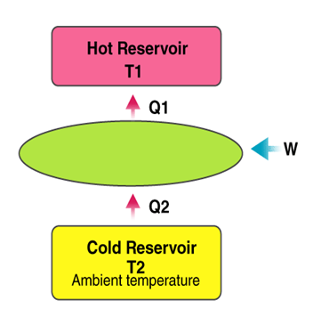
b) Mechanical or Artificial Refrigeration: Atmosphere (Thot) Refrigerated System (Tcold) δQ1 Refrigerating System (R) δW δQ2 as shown in fig. Reversed Carnot engine A mechanical refrigeration system works on the principle of reversed Carnot.
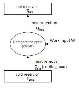
Work δw is delivered to the refrigerating system, heat δQ2 from the body or system (at lower temperature Tcold) and to deliver it along with work, δw, to another body at higher temperature, Thot, so that, Qcold+ δw = Qhot. There can be two methods by which the temperature T2 < T3 may be attained within the refrigerating system:
(i) By lowering the temperature of the working substance in the refrigerating system to the level of T2. In this case, the heat will be absorbed due to temperature difference and T3 will decrease as heat δQ2 flows out.
(ii) By evaporating some fluid at an appropriate pressure.
Key Takeaways:
- There can be two methods by which the temperature T2 < T3 may be attained within the refrigerating system:
- In this case, the heat will be absorbed due to temperature difference and T3 will decrease as heat δQ2 flows out.
Capacity of refrigeration unit is generally defined in ton of refrigeration. A ton of refrigeration is defined as the quantity of heat to be removed in order to form one ton (1000 kg) of ice at 0C in 24 hrs. From liquid water at 0C. This is equivalent to 3.5 kJ/s (3.5 kW) or 210 kJ/min.
Refrigeration effect: It is the amount of heat energy removed per unit time from the space to be cooled by the refrigeration process. It is expressed in kw or kJ/s. It is also called capacity of a refrigerator.
Coefficient of performance (COP):
It is defined as the rate of removal of heat from a substance which is to be cooled.
C.O.P is a measure of efficiency of a refrigeration system and is defined as
C.O. P = Refrigeration effect upon input energy
- The Carnot Cycle is a thermodynamic cycle that is known for the best possible efficiency.
- Carnot Cycle changes the energy available in the form of heat to produce useful work in reversible- adiabatic (isotropic).
- The Carnot cycle is known for setting the highest efficiency bench mark that any cycle or engine can achieve.
- Carnot cycle is reversible cycle.
- Refrigerators and Heat engines that work on Reversible Carnot cycles & considered as models for comparing the actual heat engines and refrigerators.
- In practical world reversible cycles cannot be achieved due to irreversibility associated with each process which cannot be eliminated.
Carnot Vapour Cycle:
- In Carnot vapor cycle working fluid is vapor.
- A Carnot cycle with two isothermal and two isentropic processes can be thought of as a vapor power cycle.
- However, in practice, it is almost impossible to design a vapor power plant, based on Carnot cycle.
- Below figure shows the schematic diagram of a simple steam power plant working on vapor power cycle and T-s diagram.
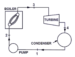
Fig. Schematic diagram of a simple steam power plant on vapor power cycle
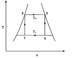
Fig. T-s diagram of vapor power cycle
- Saturated vapour leaves the boiler at state 3, enters the turbine leaves and expands to state 4.
- The fluid then enters the condenser, where it is cooled to state 1, and then it is compressed to state 2 in the pump.
- Practically, it is very difficult to, reject or heat to or from the working fluid at constant temperature.
- But it is comparatively easy to add or reject heat to or form fluid at constant pressure.
- Therefore, Carnot Vapour cycle is not used as idealized cycle in steam power plant.
Key Takeaways:
- Capacity of refrigeration unit is generally defined in ton of refrigeration. A
- It is expressed in kw or kJ/s. It is also called capacity of a refrigerator.
- The Carnot cycle is known for setting the highest efficiency bench mark that any cycle or engine can achieve.
- In practical world reversible cycles cannot be achieved due to irreversibility associated with each process which cannot be eliminated.
- Therefore, Carnot Vapour cycle is not used as idealized cycle in steam power plant.
Refrigerator:
Working
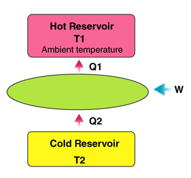
- In the refrigeration cycle, there are 5 simple additives: a fluid refrigerant; a compressor, a condenser coil, an evaporator coil, and an enlargement device.
- The compressor constricts the refrigerant vapor, elevating its pressure, and pushes it into the coils at the out of doors of the refrigerator.
- When the new fuelling with inside the coils meets the cooler air temperature of the kitchen, it will become a liquid.
- Now, with inside the liquid shape at excessive pressure, the refrigerant cools down because it flows into the coils in the freezer and the fridge.
- The refrigerant absorbs the warmth in the fridge, cooling down the air.
- Lastly, the refrigerant evaporates after which flows again to the compressor, wherein the cycle repeats itself.
Applications
- Separation of gases: Separation of air into its materials via way of means of fractional distillation as exclusive additives of air liquefies at exclusive temperatures.
- Condensation of gases: In industries, gases inclusive of ammonia are condensed earlier than garage and shipment.
- Dehumidification of air: Air is dehumidified via way of means of liquefying and isolating the moisture found in it.
- Cooling for preservation: Vegetables, organic-chemical, and explosives are saved in bloodless garage for preservation.
Heat Pump:
A warmness pump is a mechanical compression cycle that may be reversed to both warmness and cool a managed space.
Working
- A traditional warmness pump includes parts: an indoor unit referred to as an air handler and an outside unit much like an air output unit.
- A compressor circulates a refrigerant that absorbs and releases warmness because it travels among those units.
- Here, the operating fluid or the refrigerant (in its gaseous state) is pressurized via way of means of a compressor and circulated thru the system.
- The technique of compression makes the fluid hotter.
- The warm and pressurized vapor, on the release aspect of the compressor, is cooled in a warmness exchanger referred to as a condenser, till it condenses right into an excessive stress, mild temperature liquid.
- The stress of the condensed fluid is decreased the usage of a stress-decreasing tool including a capillary tube or an enlargement valve.
- The temperature of the low-stress liquid is expanded in a warmness exchanger and then the refrigerant is made to go back to the compressor and the cycle is repeated.
Applications Space heating:
- Heat pump is used to warmness an enclosed place including a workspace, greenhouses, and houses.
- Water heating: Water in industries and families is heated the usage of warmness recovered from different reactions the usage of the warmth pump.
- Process heating: In industries, the warmth pump is used to warmness the technique fluid earlier than the reactions.
- Heat recovery: Heat pump is used to get better technique warmness from different reactions.
Key Takeaways:
- When the new fuelling with inside the coils meets the cooler air temperature of the kitchen, it will become a liquid.
- Condensation of gases: In industries, gases inclusive of ammonia are condensed earlier than garage and shipment.
- A compressor circulates a refrigerant that absorbs and releases warmness because it travels among those units.
- Process heating: In industries, the warmth pump is used to warmness the technique fluid earlier than the reactions.
Air Refrigeration cycle:
1. Air is used as working fluid.
2. No change of phase throughout.
3. Heat carrying capacity/kg of air is very small compared with other refrigerant systems. High pressure air readily available in the Aircraft.
4. Low equipment weight.
Basic elements:
1. Compressor
2. Heat exchanger
3. Expander
4. Refrigerator
Open system: The air used in the refrigerator is thrown into the atmosphere.
Closed system: Air used is recirculated:
- To increase C.O.P., T2 should kept low. But cannot be reduced below 25ºC –Atmospheric Temp.
- T1 should be kept high. But cannot be increased above 0ºC. It is the required temperature.
Advantages of Air –Refrigeration Systems:
1. As the air is easily available compared with the other refrigerant, it is cheap.
2. The air used is non-flammable, so there is no danger of fire as in NH3 machine.
3. The weight of the air refrigeration system / T.R is quite low compared with the other refrigeration systems which is one of the major causes selecting this system in air craft.
Key Takeaways:
- Air is used as working fluid.
- Heat exchanger
- To increase C.O.P., T2 should kept low. But cannot be reduced below 25ºC –Atmospheric Temp.
- The air used is non-flammable, so there is no danger of fire as in NH3 machine.
Reversed Carnot cycle employing a gas Reversed Carnot cycle is an ideal refrigeration cycle for constant temperature external heat source and heat sinks.
Figure 1 (a) shows the schematic of a reversed Carnot refrigeration system using a gas as the working fluid along with the cycle diagram on T-s and P-V coordinates. As shown, the cycle consists of the following four processes:
- Process 1-2: Reversible, adiabatic compression in a compressor
- Process 2-3: Reversible, isothermal heat rejection in a compressor
- Process 3-4: Reversible, adiabatic expansion in a turbine
- Process 4-1: Reversible, isothermal heat absorption in a turbine
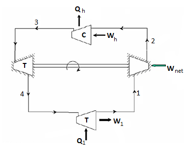
Fig.(a). Schematic of a reverse Carnot refrigeration system
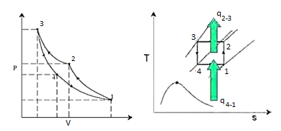
Fig.(b). Reverse Carnot refrigeration system in P-v and T-s coordinates
The heat transferred during isothermal processes 2-3 and 4-1 are given by:


Applying first law of thermodynamics to the closed cycle,

The work of isentropic expansion,  exactly matches the work of isentropic compression
The COP of Carnot system is given by:

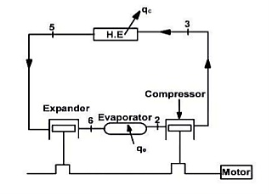
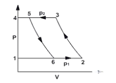
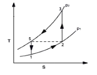
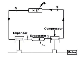
- The components of the air refrigeration system are shown in Fig. In this system, air is taken into the compressor from atmosphere and compressed. The hot compressed air is cooled in heat exchanger up to the atmospheric temperature (in ideal conditions). The cooled air is then expanded in an expander.
- The temperature of the air coming out from the expander is below the atmospheric temperature due to isentropic expansion. The low temperature air coming out from the expander enters into the evaporator and absorbs the heat. The cycle is repeated again.
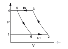
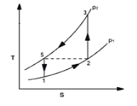
- The working of air refrigeration cycle is represented on p-v and T-s diagrams in Fig.
4. Assumptions:
(1) The compression and expansion processes are reversible adiabatic processes.
(2) There is a perfect inter-cooling in the heat exchanger.
(3) There are no pressure losses in the system.
Key Takeaways:
- The components of the air refrigeration system are shown in Fig. In this system, air is taken into the compressor from atmosphere and compressed
- The cooled air is then expanded in an expander.
- The compression and expansion processes are reversible adiabatic processes.
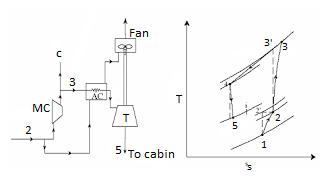
Figure shows the schematic of a simple aircraft refrigeration system and the operating cycle on T-s diagram.
This is an open system. As shown in the T-s diagram, the outside low pressure and low temperature air (state 1) is compressed due to ram effect to ram pressure (state 2).
During this process its temperature increases from 1 to 2. This air is compressed in the main compressor to state 3, and is cooled to state 4 in the air cooler. Its pressure is reduced to cabin pressure in the turbine (state 5), as a result its temperature drops from 4 to 5. The cold air at state 5 is supplied to the cabin. It picks up heat as it flows through the cabin providing useful cooling effect. The power output of the turbine is used to drive the fan, which maintains the required air flow over the air cooler. This simple system is good for ground cooling (when the aircraft is not moving) as fan can continue to maintain airflow over the air cooler.
By applying steady flow energy equation to the ramming process, the temperature rise at the end of the ram effect can be shown to be:

Where ‘M’ is the Mach number, which is the velocity of the aircraft ‘C’ to the sonic velocity ‘a’.

Due to irreversibility, the actual pressure at the end of the ramming will be less than the pressure resulting from isentropic compression. The ratio of actual pressure rise to the isentropic pressure rise is called ram efficiency.

The refrigeration capacity of the simple aircraft cycle is ‘Q’ is given by:

Where m is the mass flow rate of air through turbine.
Key Takeaways:
- Its pressure is reduced to cabin pressure in the turbine (state 5), as a result its temperature drops from 4 to 5. The cold air at state 5 is supplied to the cabin.
- The ratio of actual pressure rise to the isentropic pressure rise is called ram efficiency.
The various types of aircraft air refrigeration systems used these days are:
- Simple air-cooling system
- Simple air evaporative cooling system
- Boot strap air cooling system
- Boot strap air evaporative cooling system
- Reduced ambient air-cooling system
- Regenerative air-cooling system.
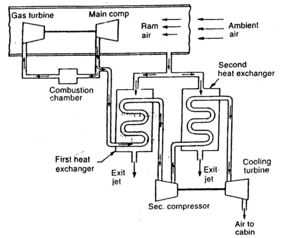
Fig. Bootstrap air refrigeration system
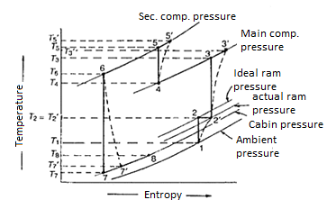
Fig. T-s Diagram of Bootstrap System
- The Bootstrap system shown in figure has two heat exchangers instead of one and the expansion turbine drives a compressor rather than a fan.
- Thus, it cannot be used for ground cooling.
- The primary purpose of Bootstrap system is to provide an additional cooling capacity when the primary source of air does not have a sufficiently high pressure to provide the amount of cooling required.
- The turbine drives the secondary compressor to rise the pressure of primary air before it enters the turbine.
- It is used for high-speed aircraft where in the velocity of the aircraft provides the necessary airflow for the heat exchangers, as a result a separate fan is not required.
Regenerative Air Refrigeration System:
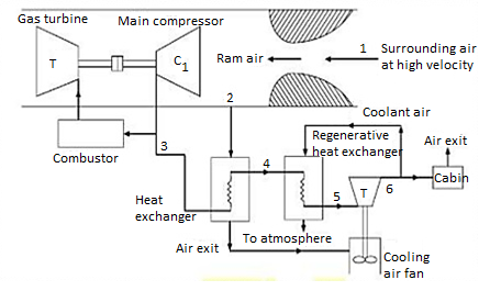
Fig. Regenerative system
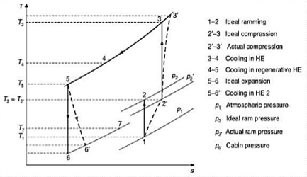
Fig. T-S diagram of Regenerative system
The regenerative system shown in figure also has two heat exchangers but does not required ram air for cooling the air in the second heat exchanger. It is a modification of the simple system with the addition of a secondary heat exchanger in which the air from the primary heat exchanger is further cooled with a portion of the refrigerated air bled after expansion in the turbine as shown in figure. It provides lower turbine discharge temperatures but at the expense of some weight and complications.
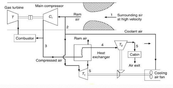
Fig. Reduced Ambient Air Refrigeration System
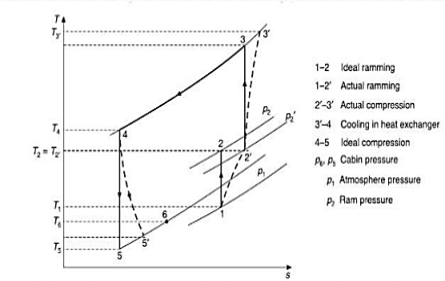
Fig. T-S Diagram of Reduced Ambient System
- In the reduced ambient system, there are two expansion turbines-one in the cabin air stream and the other in the cooling air streams.
- Both turbines are connected to the shaft driving the fan which absorbs all the power.
- The turbine for the ram air operates from the pressure ratio made available by the ram air pressure.
- The cooling turbine reduces the temperature of cooling air to level of static temperature of ambient air.
- Thus, primary compressed air can be cooled to, say T4 below the stagnation temperature T2 and a little above the static temperature T1.
- DART is the index used to compare different aircraft cooling system.
- It is defined as the temperature of air at the exit of the cooling turbine in the absence of any moisture condensation.
- Thus, the capacity of the machine giving m. Kg/sec of air at a DART of
 to maintain a cabin at temperature (
 ) is
) is
 = m
= m  (
(  –
–  )
)
Key Takeaways:
- The turbine drives the secondary compressor to rise the pressure of primary air before it enters the turbine.
- It provides lower turbine discharge temperatures but at the expense of some weight and complications.
- Both turbines are connected to the shaft driving the fan which absorbs all the power.
- It is defined as the temperature of air at the exit of the cooling turbine in the absence of any moisture condensation.
References:
1. Refrigeration and Air conditioning by C.P Arora, McGraw‐Hill
2. Refrigeration and Air conditioning, by Manohar Prasad, New Age International (P) Ltd. Pub.
3. Refrigeration and Air conditioning by R.C. Arora, PHI
4. Principles of Refrigeration by Roy J. Dossat. Pearson Education
5. Refrigeration and Air conditioning by Stoecker& Jones. McGraw‐Hill
Unit – 1
Refrigeration
Refrigeration
- Mechanical refrigeration is a process of lowering the temperature of a substance less than that of its surroundings.
- Capacity of refrigeration is expressed in tone.
- A tone of refrigeration is expressed in designed as the rate of heat removed from the surroundings equivalent to the heat required for melting one tone of ice in one day.
- It is defined as the science of providing and maintaining temperature below that of surrounding atmosphere.
- It means that continuously extraction of heat from a body whose temperature is already below the temperature of its surrounding.
The process of keeping an item below room temperature by storing the item in a system or substance designed to cool or freeze.
The most common form of refrigeration is provided by systems (i.e., Refrigerators) that use a refrigerant chemical to remove heat from items stored inside the system.
The main purpose of refrigeration was to produce ice, which was used for cooling beverages, food preservation and refrigerated transport etc.
The major applications of refrigeration can be grouped into following four major equally important areas:
1. Food processing, preservation and distribution
2. Chemical and process industries
3. Special Applications
4. Comfort air-conditioning
Air – Conditioning:
- Air conditioning refers to the treatment of air so as to simultaneously control its temperature, humid moisture content, quality and circulation.
- Air-conditioning is one of the major applications of refrigeration.
- Air-conditioning has made the living conditions more comfortable, hygienic and healthy in offices, work places and homes.
- Air-conditioning involves cooling and dehumidification in summer months; this is essentially done by refrigeration.
Key Takeaways:
- It means that continuously extraction of heat from a body whose temperature is already below the temperature of its surrounding.
- The main purpose of refrigeration was to produce ice, which was used for cooling beverages, food preservation and refrigerated transport etc.
- Air-conditioning is one of the major applications of refrigeration.
a) Natural Method: The natural method includes the utilization of ice or snow obtained naturally in cold climate. Ice melts at 00 C. So, when it is placed in space or system warmer than 00 C, heat is absorbed by the ice and the space is cooled. The ice then melts into water by absorbing its latent heat at the rate of 324 kJ/kg. But, now-a-days, refrigeration requirements have become so high that the natural methods are inadequate and therefore obsolete.
b) Mechanical or Artificial Refrigeration: Atmosphere (Thot) Refrigerated System (Tcold) δQ1 Refrigerating System (R) δW δQ2 as shown in fig. Reversed Carnot engine A mechanical refrigeration system works on the principle of reversed Carnot.
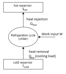
Work δw is delivered to the refrigerating system, heat δQ2 from the body or system (at lower temperature Tcold) and to deliver it along with work, δw, to another body at higher temperature, Thot, so that, Qcold+ δw = Qhot. There can be two methods by which the temperature T2 < T3 may be attained within the refrigerating system:
(i) By lowering the temperature of the working substance in the refrigerating system to the level of T2. In this case, the heat will be absorbed due to temperature difference and T3 will decrease as heat δQ2 flows out.
(ii) By evaporating some fluid at an appropriate pressure.
Key Takeaways:
- There can be two methods by which the temperature T2 < T3 may be attained within the refrigerating system:
- In this case, the heat will be absorbed due to temperature difference and T3 will decrease as heat δQ2 flows out.
Capacity of refrigeration unit is generally defined in ton of refrigeration. A ton of refrigeration is defined as the quantity of heat to be removed in order to form one ton (1000 kg) of ice at 0C in 24 hrs. From liquid water at 0C. This is equivalent to 3.5 kJ/s (3.5 kW) or 210 kJ/min.
Refrigeration effect: It is the amount of heat energy removed per unit time from the space to be cooled by the refrigeration process. It is expressed in kw or kJ/s. It is also called capacity of a refrigerator.
Coefficient of performance (COP):
It is defined as the rate of removal of heat from a substance which is to be cooled.
C.O.P is a measure of efficiency of a refrigeration system and is defined as
C.O. P = Refrigeration effect upon input energy
- The Carnot Cycle is a thermodynamic cycle that is known for the best possible efficiency.
- Carnot Cycle changes the energy available in the form of heat to produce useful work in reversible- adiabatic (isotropic).
- The Carnot cycle is known for setting the highest efficiency bench mark that any cycle or engine can achieve.
- Carnot cycle is reversible cycle.
- Refrigerators and Heat engines that work on Reversible Carnot cycles & considered as models for comparing the actual heat engines and refrigerators.
- In practical world reversible cycles cannot be achieved due to irreversibility associated with each process which cannot be eliminated.
Carnot Vapour Cycle:
- In Carnot vapor cycle working fluid is vapor.
- A Carnot cycle with two isothermal and two isentropic processes can be thought of as a vapor power cycle.
- However, in practice, it is almost impossible to design a vapor power plant, based on Carnot cycle.
- Below figure shows the schematic diagram of a simple steam power plant working on vapor power cycle and T-s diagram.
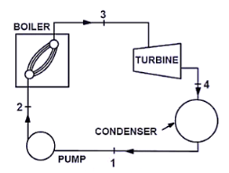
Fig. Schematic diagram of a simple steam power plant on vapor power cycle
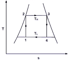
Fig. T-s diagram of vapor power cycle
- Saturated vapour leaves the boiler at state 3, enters the turbine leaves and expands to state 4.
- The fluid then enters the condenser, where it is cooled to state 1, and then it is compressed to state 2 in the pump.
- Practically, it is very difficult to, reject or heat to or from the working fluid at constant temperature.
- But it is comparatively easy to add or reject heat to or form fluid at constant pressure.
- Therefore, Carnot Vapour cycle is not used as idealized cycle in steam power plant.
Key Takeaways:
- Capacity of refrigeration unit is generally defined in ton of refrigeration. A
- It is expressed in kw or kJ/s. It is also called capacity of a refrigerator.
- The Carnot cycle is known for setting the highest efficiency bench mark that any cycle or engine can achieve.
- In practical world reversible cycles cannot be achieved due to irreversibility associated with each process which cannot be eliminated.
- Therefore, Carnot Vapour cycle is not used as idealized cycle in steam power plant.
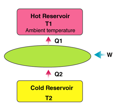
Refrigerator:
Working
- In the refrigeration cycle, there are 5 simple additives: a fluid refrigerant; a compressor, a condenser coil, an evaporator coil, and an enlargement device.
- The compressor constricts the refrigerant vapor, elevating its pressure, and pushes it into the coils at the out of doors of the refrigerator.
- When the new fuelling with inside the coils meets the cooler air temperature of the kitchen, it will become a liquid.
- Now, with inside the liquid shape at excessive pressure, the refrigerant cools down because it flows into the coils in the freezer and the fridge.
- The refrigerant absorbs the warmth in the fridge, cooling down the air.
- Lastly, the refrigerant evaporates after which flows again to the compressor, wherein the cycle repeats itself.
Applications
- Separation of gases: Separation of air into its materials via way of means of fractional distillation as exclusive additives of air liquefies at exclusive temperatures.
- Condensation of gases: In industries, gases inclusive of ammonia are condensed earlier than garage and shipment.
- Dehumidification of air: Air is dehumidified via way of means of liquefying and isolating the moisture found in it.
- Cooling for preservation: Vegetables, organic-chemical, and explosives are saved in bloodless garage for preservation.
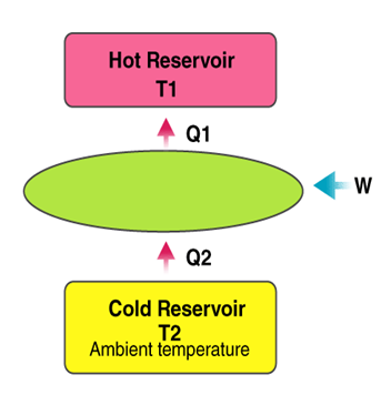
Heat Pump:
A warmness pump is a mechanical compression cycle that may be reversed to both warmness and cool a managed space.
Working
- A traditional warmness pump includes parts: an indoor unit referred to as an air handler and an outside unit much like an air output unit.
- A compressor circulates a refrigerant that absorbs and releases warmness because it travels among those units.
- Here, the operating fluid or the refrigerant (in its gaseous state) is pressurized via way of means of a compressor and circulated thru the system.
- The technique of compression makes the fluid hotter.
- The warm and pressurized vapor, on the release aspect of the compressor, is cooled in a warmness exchanger referred to as a condenser, till it condenses right into an excessive stress, mild temperature liquid.
- The stress of the condensed fluid is decreased the usage of a stress-decreasing tool including a capillary tube or an enlargement valve.
- The temperature of the low-stress liquid is expanded in a warmness exchanger and then the refrigerant is made to go back to the compressor and the cycle is repeated.
Applications Space heating:
- Heat pump is used to warmness an enclosed place including a workspace, greenhouses, and houses.
- Water heating: Water in industries and families is heated the usage of warmness recovered from different reactions the usage of the warmth pump.
- Process heating: In industries, the warmth pump is used to warmness the technique fluid earlier than the reactions.
- Heat recovery: Heat pump is used to get better technique warmness from different reactions.
Key Takeaways:
- When the new fuelling with inside the coils meets the cooler air temperature of the kitchen, it will become a liquid.
- Condensation of gases: In industries, gases inclusive of ammonia are condensed earlier than garage and shipment.
- A compressor circulates a refrigerant that absorbs and releases warmness because it travels among those units.
- Process heating: In industries, the warmth pump is used to warmness the technique fluid earlier than the reactions.
Air Refrigeration cycle:
1. Air is used as working fluid.
2. No change of phase throughout.
3. Heat carrying capacity/kg of air is very small compared with other refrigerant systems. High pressure air readily available in the Aircraft.
4. Low equipment weight.
Basic elements:
1. Compressor
2. Heat exchanger
3. Expander
4. Refrigerator
Open system: The air used in the refrigerator is thrown into the atmosphere.
Closed system: Air used is recirculated:
- To increase C.O.P., T2 should kept low. But cannot be reduced below 25ºC –Atmospheric Temp.
- T1 should be kept high. But cannot be increased above 0ºC. It is the required temperature.
Advantages of Air –Refrigeration Systems:
1. As the air is easily available compared with the other refrigerant, it is cheap.
2. The air used is non-flammable, so there is no danger of fire as in NH3 machine.
3. The weight of the air refrigeration system / T.R is quite low compared with the other refrigeration systems which is one of the major causes selecting this system in air craft.
Key Takeaways:
- Air is used as working fluid.
- Heat exchanger
- To increase C.O.P., T2 should kept low. But cannot be reduced below 25ºC –Atmospheric Temp.
- The air used is non-flammable, so there is no danger of fire as in NH3 machine.
Reversed Carnot cycle employing a gas Reversed Carnot cycle is an ideal refrigeration cycle for constant temperature external heat source and heat sinks.
Figure 1 (a) shows the schematic of a reversed Carnot refrigeration system using a gas as the working fluid along with the cycle diagram on T-s and P-V coordinates. As shown, the cycle consists of the following four processes:
- Process 1-2: Reversible, adiabatic compression in a compressor
- Process 2-3: Reversible, isothermal heat rejection in a compressor
- Process 3-4: Reversible, adiabatic expansion in a turbine
- Process 4-1: Reversible, isothermal heat absorption in a turbine
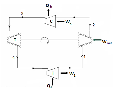
Fig.(a). Schematic of a reverse Carnot refrigeration system
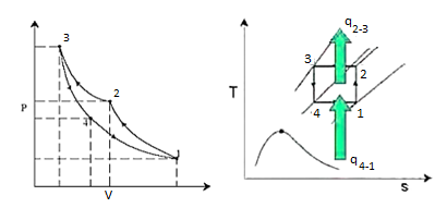
Fig.(b). Reverse Carnot refrigeration system in P-v and T-s coordinates
The heat transferred during isothermal processes 2-3 and 4-1 are given by:


Applying first law of thermodynamics to the closed cycle,

The work of isentropic expansion,  exactly matches the work of isentropic compression
The COP of Carnot system is given by:

- The components of the air refrigeration system are shown in Fig. In this system, air is taken into the compressor from atmosphere and compressed. The hot compressed air is cooled in heat exchanger up to the atmospheric temperature (in ideal conditions). The cooled air is then expanded in an expander.
- The temperature of the air coming out from the expander is below the atmospheric temperature due to isentropic expansion. The low temperature air coming out from the expander enters into the evaporator and absorbs the heat. The cycle is repeated again.
- The working of air refrigeration cycle is represented on p-v and T-s diagrams in Fig.
4. Assumptions:
(1) The compression and expansion processes are reversible adiabatic processes.
(2) There is a perfect inter-cooling in the heat exchanger.
(3) There are no pressure losses in the system.
Key Takeaways:
- The components of the air refrigeration system are shown in Fig. In this system, air is taken into the compressor from atmosphere and compressed
- The cooled air is then expanded in an expander.
- The compression and expansion processes are reversible adiabatic processes.
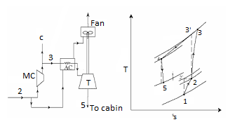
Figure shows the schematic of a simple aircraft refrigeration system and the operating cycle on T-s diagram.
This is an open system. As shown in the T-s diagram, the outside low pressure and low temperature air (state 1) is compressed due to ram effect to ram pressure (state 2).
During this process its temperature increases from 1 to 2. This air is compressed in the main compressor to state 3, and is cooled to state 4 in the air cooler. Its pressure is reduced to cabin pressure in the turbine (state 5), as a result its temperature drops from 4 to 5. The cold air at state 5 is supplied to the cabin. It picks up heat as it flows through the cabin providing useful cooling effect. The power output of the turbine is used to drive the fan, which maintains the required air flow over the air cooler. This simple system is good for ground cooling (when the aircraft is not moving) as fan can continue to maintain airflow over the air cooler.
By applying steady flow energy equation to the ramming process, the temperature rise at the end of the ram effect can be shown to be:

Where ‘M’ is the Mach number, which is the velocity of the aircraft ‘C’ to the sonic velocity ‘a’.

Due to irreversibility, the actual pressure at the end of the ramming will be less than the pressure resulting from isentropic compression. The ratio of actual pressure rise to the isentropic pressure rise is called ram efficiency.

The refrigeration capacity of the simple aircraft cycle is ‘Q’ is given by:

Where m is the mass flow rate of air through turbine.
Key Takeaways:
- Its pressure is reduced to cabin pressure in the turbine (state 5), as a result its temperature drops from 4 to 5. The cold air at state 5 is supplied to the cabin.
- The ratio of actual pressure rise to the isentropic pressure rise is called ram efficiency.
The various types of aircraft air refrigeration systems used these days are:
- Simple air-cooling system
- Simple air evaporative cooling system
- Boot strap air cooling system
- Boot strap air evaporative cooling system
- Reduced ambient air-cooling system
- Regenerative air-cooling system.
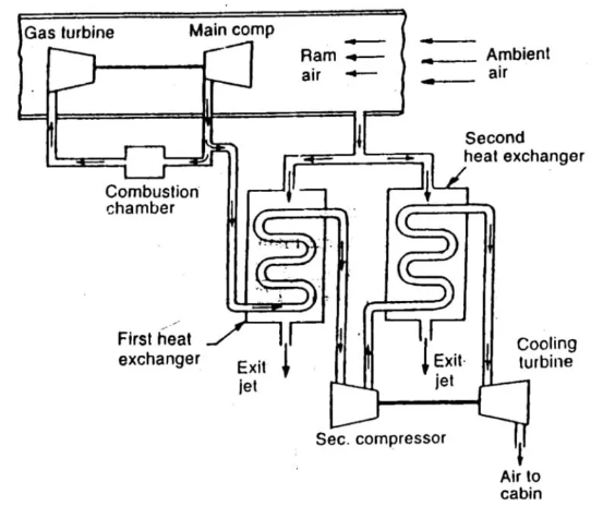
Fig. Bootstrap air refrigeration system
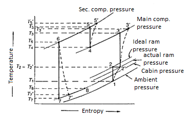
Fig. T-s Diagram of Bootstrap System
- The Bootstrap system shown in figure has two heat exchangers instead of one and the expansion turbine drives a compressor rather than a fan.
- Thus, it cannot be used for ground cooling.
- The primary purpose of Bootstrap system is to provide an additional cooling capacity when the primary source of air does not have a sufficiently high pressure to provide the amount of cooling required.
- The turbine drives the secondary compressor to rise the pressure of primary air before it enters the turbine.
- It is used for high-speed aircraft where in the velocity of the aircraft provides the necessary airflow for the heat exchangers, as a result a separate fan is not required.
Regenerative Air Refrigeration System:
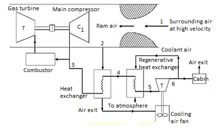
Fig. Regenerative system
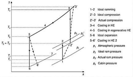
Fig. T-S diagram of Regenerative system
The regenerative system shown in figure also has two heat exchangers but does not required ram air for cooling the air in the second heat exchanger. It is a modification of the simple system with the addition of a secondary heat exchanger in which the air from the primary heat exchanger is further cooled with a portion of the refrigerated air bled after expansion in the turbine as shown in figure. It provides lower turbine discharge temperatures but at the expense of some weight and complications.
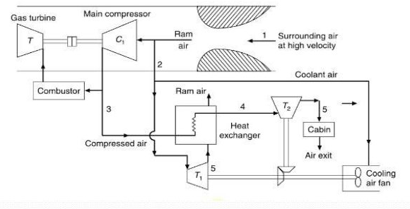
Fig. Reduced Ambient Air Refrigeration System
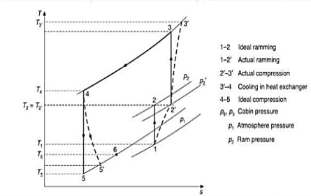
Fig. T-S Diagram of Reduced Ambient System
- In the reduced ambient system, there are two expansion turbines-one in the cabin air stream and the other in the cooling air streams.
- Both turbines are connected to the shaft driving the fan which absorbs all the power.
- The turbine for the ram air operates from the pressure ratio made available by the ram air pressure.
- The cooling turbine reduces the temperature of cooling air to level of static temperature of ambient air.
- Thus, primary compressed air can be cooled to, say T4 below the stagnation temperature T2 and a little above the static temperature T1.
- DART is the index used to compare different aircraft cooling system.
- It is defined as the temperature of air at the exit of the cooling turbine in the absence of any moisture condensation.
- Thus, the capacity of the machine giving m. Kg/sec of air at a DART of
 to maintain a cabin at temperature (
 ) is
) is
 = m
= m  (
(  –
–  )
)
Key Takeaways:
- The turbine drives the secondary compressor to rise the pressure of primary air before it enters the turbine.
- It provides lower turbine discharge temperatures but at the expense of some weight and complications.
- Both turbines are connected to the shaft driving the fan which absorbs all the power.
- It is defined as the temperature of air at the exit of the cooling turbine in the absence of any moisture condensation.
References:
1. Refrigeration and Air conditioning by C.P Arora, McGraw‐Hill
2. Refrigeration and Air conditioning, by Manohar Prasad, New Age International (P) Ltd. Pub.
3. Refrigeration and Air conditioning by R.C. Arora, PHI
4. Principles of Refrigeration by Roy J. Dossat. Pearson Education
5. Refrigeration and Air conditioning by Stoecker& Jones. McGraw‐Hill