Unit-1
Introduction, Velocity analysis and Acceleration analysis
Sr. No. | Machine | Mechanism |
1. | Machine may have many mechanisms for transmitting mechanical work or power | When one of the link of a kinematic chain is fixed, then the chain is called a mechanism. |
2. | The basic function of m/c is to obtain mechanical advantage | Mechanism transmits and modifies the motion only. |
3. | Lathe, Millins, Shaper, Heat engine etc. | Geneva, Quick return, slider crank, Four bar mechanism etc. |
Kinematics: It is the branch of theory of machine which deals with the study of relative motion of the parts of the machine, neglecting consideration of forces producing it.
Kinetics: It is the study of the reason how a body respond when a force or a torque is applied on it. It deals with the reason of motion by considering the statical frictional force.
Each part of a machine, which moves relative to some other part is known as a kinematic link.
A link or element need not be a rigid body, but it must be resistance body.
A body is said to be a resistant body if it is capable of transmitting the required forces with negligible deformation.
Link has the following two characteristics:
It should have relative motion.
It must be a resistant body.
A rigid link is one which does not undergo any deformation while transmitting motion.
Perfectly rigid links do not exist.
E.g. in reciprocating engine, deformation of crank, connection rod is negligible, they can be considered as rigid links.
Flexible link:
A flexible link is one which is partly deformed in a manner not to affect the transmission of motion.
E.g. Belts, ropes, chains and wires are flexible links and transmit tensile forces only.
Fluid link:
A link which transmit the motion by fluid pressure
E.g. hydraulic press, jacks and breaks.
Key takeaway: The basic types of link are rigid, flexible and fluid.
Classification of kinematic pairs is based on the following considerations
According to the type of nature of relative motion between the links:
When the two elements of a pair are connected in such a way that one can only side relative to the other, the pair is known as a sliding pair.
Sliding pair has a completely constrained motion.
Example.- The piston and cylinder cross head and guides of a reciprocating steam engine, ram and its guides in shaper tail stock on the lathe bed square bar in a square hole, it is also known as perismatic sliding pair
2. Turning pair (Revolute pair or pin Joint):
When the two links of a pair are connected in such a way that one can only turn or revolve about a fixed axis of another links, the pair is known as turning pair.
A turning pair also has a completely constrained motion
For example: A shaft with collars at both ends fitted into a circular hole, The crankshaft in a journal bearing in an engine,Lathe spindle supported in head stock, Cycle wheels turning over their axles.
3. Rolling pair
When the two links of a pair are connected in such a way that one rolls over another fixed link, the pair is known as rolling pair.
Examples: Ball and roller bearings, Wheel rolling on a flat surface, Toothed gears, Belt drive – pulley can be considered to be rolling on the belt.
4. Screw Pair (Helical pair)
Screw pair is formed when contact surfaces of two links are screw threads, in which one link turns as well as slides into the link.
Example: Motion of the bolt in the fixed nut, Machine vice, C – clamp.
5. Spherical Pair (Globular Pair)
Spherical pair is formed when the two links are connected in such a way that, one link (of spherical shape) turns or swivels about the another fixed link
Example: The ball and socket joint, Attachment of a car mirror, Pen stand, Joy stick.
According to the type of contact between the link:
When the two elements of a pair have surface contact when relative motion takes place and the surface of one element slides over the surface of the other.
Example: All types of sliding pairs, turning pairs and screw pairs from lower joints.
2. Higher Pair
When the two elements of a pair have a line or point contact when relative motion takes place and the motion between the two links is partly turning and partly sliding.
Example: A pair of friction disc, toothed gearing, belt and rope drives, ball and roller bearings, cam and follower,
According to the nature of Mechanical constraints:
1. Self closed pair
When the two elements of a pair are connected together mechanically in such a way that only required kind of relative motion occurs, it is known as self closed pair.
E.g. The lower pairs are self closed pair.
2. Force closed pair (unclosed pair)
When the two links of a pair are not connected mechanically but are kept in contact by the action of external forces, the pairs is said to be a force – closed pair.
E.g. The cam and follower is an example of force closed pair, as it kept in contact by the forces exerted by spring and gravity.
Key Takeaway: The kinematic pair is classified into various categories depending upon the certain conditions, according to the nature of Mechanical constraints, according to the type of contact between the link, according to the type of nature of relative motion between the links.
When the motion between a pair is in a definite direction irrespective of the direction of force applied, then the motion is said to be completely constrained motion.
E.g. motion of the piston in a cylinder (only reciprocating motion), square bar in a square hole, shaft with collars in a circular hole
Incompletely constrained motion
When the motion between a pair or two links can take place in more than one direction, then the motion is called as incompletely constrained motion. The change in the direction of impressed force may change the direction of relative motion between the pair.
E.g. a circular shaft or bar in a circular hole.
Successfully constrained motion
When the motion between two elements of a pair is possible in more than one direction but is made to have motion only in one direction by using some external means, it is called as a successfully constrained motion.
E.g. a shaft in a foot – step bearing in which shaft may rotate in a bearing or it may move upwards. This the case of incompletely constrained motion, but if the load is placed on the shaft to prevent axial upward movement of the shaft then the motion is said to be successfully constrained motion.
Key takeaways: Basically there are three classifications of constraints of motion in pairs, that is complete, incomplete and successfully constraint motion.
It is defined as the number of independent variables that must be specified to define completely the condition of the system.
Consider an unconstrained rigid body in a space which can describe the following motions.
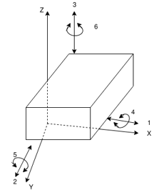
Figure. Degree of freedom of a rigid body
Translational Motions along any three perpendicular axe
Rotational motions about the same axes
 Thus, an unconstrained rigid body in a space have six degrees of freedom.
E.g.
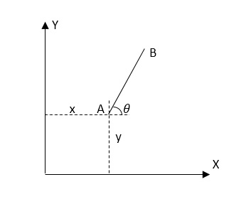
An unconstrained rigid link in the plane has three degrees of freedom (x, y, Q)
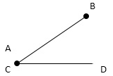
(DOF = 3)If link AB is connected to the link CD by a turning pair at A.
i.e. each pin joint or revolute pair will remove two degrees of freedom.
Only Q is required to specify the motion (DOF = 1)
Note:
Each link of a mechanism has three degrees of freedom before it is connected ot any other link.
Each turning pair or revolute pair or pin joint will remove two degrees of freedom.

Key Takeaway: Mobility is defined as the number of independent variables that must be specified to define completely the condition of the system.
i.e. n = 1, h = 0


The above equation is called as Grubler’s criterion of plane mechanism with single degree of freedom and kinematic pairs cannot have odd number of links.
Key Takeaway:  This is the basic formula of Grubler’s equation.
Numerical:
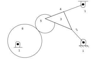
No. of links = 6
No. of joints or lower pairs = 6
No. of higher pairs = 1
As the number of degrees of freedom is 2, it means two separate input motions are required to produce constrained motion for the mechanism.
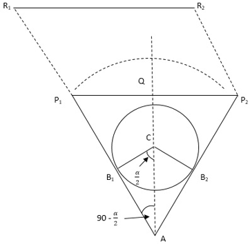
2. In a whit worth quick return mechanism, if length of driving link is 400 mm, what should be the distance between the fixed pivots if required time ratio of forward stroke: return stroke is 2:1.
Answer: Given data:
Length of driving link B1C = 400 mm = 0.4 m
Time ratio of forward stroke to return stroke = 2
To find – Distance between the fixed pivots (AC)
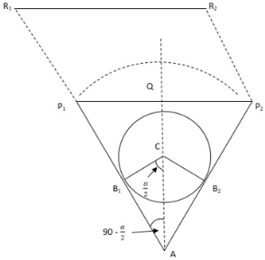
Step 1
Calculate inclination of the bar i.e. angle 


Step 2
Calculate the distance between the fixed pivots
Consider  ,
, 


When one of the element or link of a kinematic chain is fixed, the arrangement may be used for transmitting or transforming motion, this arrangement is known as mechanism.
Examples: Clocks, watches, spring toys etc.
When one of links is fixed in a kinematic chain, it is called a mechanism.
So, we can obtain as many mechanisms by fixing the different links in a kinematic chain.
This method of obtaining different mechanisms by fixing different links in a kinematic chain, is known as inversion of mechanism.
The classification of various possible mechanism of kinematic chains with four lower pairs (sliding pair or turning pair is as follows.
Four bar chair or quadric cyclic chain (Four turning pairs)
Single slider crank chain (Three turning and one sliding pairs)
Double slider crank chain (Two turning and two sliding pairs)
1.10.1 Inversion of Four bar chain
The simplest and basic kinematic chain is a four bar chain or quadric cyclic chain.
It consist of four links, each of them form a turning pair at A, B, C and D
The four links may be of different lengths.
Grashoff’s Law
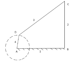
Statement
For a four bar mechanism, the sum of the shortest and longest link lengths should not be greater than the sum of the remaining two links length if there is to be continuous relative motion between the two links.
The mechanism in which no link makes a complete revolution will not be useful.
In a four bar chain, one of the links, in particular the shortest link, will make a complete revolution, if it satisfied the Grashof’s law, such a link is known as crank or driver. In Fig. link 4 ‘AD’ is a crank.
The link 2 ‘BC’ which makes a partial motion or oscillates is known as Lever or rocker or follower.
The link 3 ‘CD’ which connects the crank and lever is called connecting rod or coupler.
The fixed link 4 ‘AB’ is known as frame.
When the crank (link 4) is the driver, the mechanism is transforming rotary motion into oscillating motion.
According to Grashoff’s law.

If the above condition is not satisfied, then no link will make a complete revolution relative to any other link and the linkage is called as non – Grashoffian for bar chain.
Inversions of four Bar chain:
Beam Engine (Crank – rocker or crank – lever or rotary – oscillating converter) Mechanism
If any of the adjacent links of link ‘d’ i.e. a or c is fixed, d can have a full revolution (crank) and the link opposite to it oscillates (rocks).
In below Fig. 1. a is fixed, d is the crank and b oscillates where as in Fig. 2 C is fixed, d is the crank and b oscillates. The mechanism is known as crank – rocker, OR crank – lever mechanism or rotary – oscillating converter.
A part of the mechanism of beam engine which consist of four links, is shown in fig.
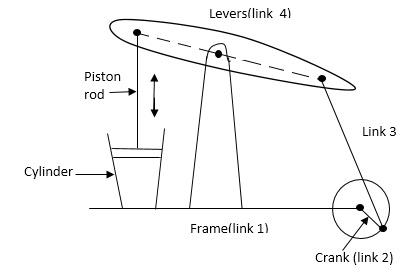
Inversion of four bar chain or mechanism:
(a) Crank Lever Mechanism:
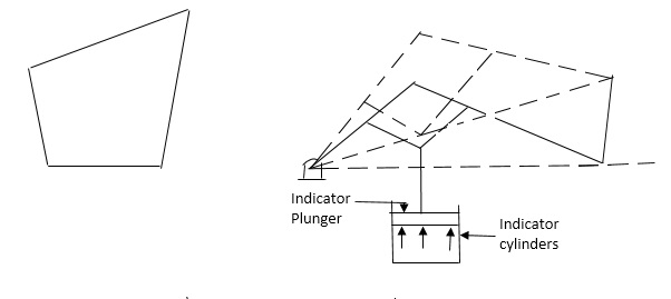
Figure: beam engine
In this mechanism, when the crank rotates about the fixed centre A, the lever oscillates about a fixed centre D. the end E of the lever CDE is connected to a piston rod which reciprocates due to the rotation of the crank:
The purpose of this mechanism is to convert rotary motion into reciprocating motion.
Watt’s Indicator (Double rocker OR double – lever mechanism or oscillating – oscillating converter)
If the link opposite to the shortest link, i.e. link b is fixed and the shortest link d is made a coupler, the other two links a and c could oscillate (below fig. 1). The mechanism is known as a rocker – rocker or double – rocker or double – lever mechanism.
The four links are – fixed link at A, link AC, link CE and link BFD. It may be noted that BF and FD from one link because these two parts have no relative motion between them.
The links CE and BFD act as levers. The displacement of the link BFD is directly proportional to the pressure of gas or steam which acts on the indicator plunger.
(b) Double Lever Mechanism (Watt’s Indicator Mechanism):
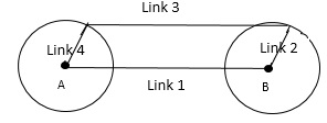
Figure: Watt’s Indicator mechanism
On any small displacement of the mechanism, the tracing point E at the end of the link CE. Traces out approximately a straight line.
The initial position of the mechanism is shown in above figure. By full lines whereas the dotted lines show the position of the mechanism when the gas or steam pressure acts on the indicator plunger.
(c) Coupling rod of a locomotive (Double crank mechanism)
In this mechanism the links AD and BC (having equ length) act as cranks and are connected to the respective wheels. The link CD acts as a coupling rod and th link AB is fixed in order to maintain a constant centre to centre distance between them.
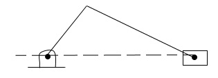
Figure: coupling rod of a locomotive
This mechanism is meant for transmitting rotary motion form one wheel to the other wheel.
1.10.2 Inversion of Slider crank chain
A single slider crank chain is a modification of the basic four bar chain. It consist of one sliding pair and three turning pairs. It is usually found in reciprocating steam engine mechanism. This type of mechanism converts rotary motion into reciprocating motion and vice versa.
Inversions of single slider crank chain:
(a) First Inversion:
Reciprocating engine
Reciprocating compressor
This inversion is obtained when link 1 is fixed and links 2 and 4 are made the crank and the slider respectively. (Fig.1)
As shown in Fig. 2 if it is a reciprocating engine, 4 (piston) is the driver and if it is a compressor 2 (crank) is the driven.
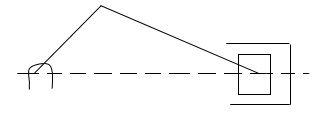
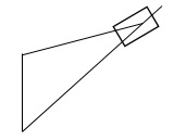
Figure: Reciprocating compressor
(b) Second Inversion:
Whitworth quick – return mechanism
Rotary engine
Fixing of the link 2 of a slider – crank chain results in the second inversion.
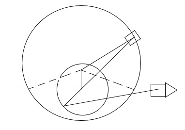
Figure: Whitworth quick – return mechanism
From Figure, when link 2 is fixed instead of link 1 the link 3 along with the slider at its end B become a crank. This makes the link 1 to rotate about 0 along with the slider which also reciprocates on it.
Whitworth quick – return mechanism (Shaper machine)
It is a mechanism used in workshops to cut metals. The forward stroke takes a little longer and cuts the metal whereas the return stroke is idle and takes a shorter period.
Slider 4 rotates in a circle about A and slides on the link 1. C is a point on the link 1 extended backwards where the link 5 is pivoted. The other end of the link 5 is pivoted to the tool, the forward stroke of which cuts the metal.
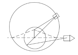
Figure: Whitworth quick – return mechanism.
The axis of motion of the slider 6 (tool) passes through o and is perpendicular to OA, the fixed link. The crank 3 rotates in the counter – clockwise direction. Initially, let the slider 4 be at B’ so that C be at C’.
Cutting tool 6 will be in the extreme left position. With the movement of the crank, the slider traverses the path B’BB’’ whereas the point C moves through C’CC’’.
Cutting tool 6 will have the forward stroke.
Finally, the slider B assumes the position B’’ and the cutting tool 6 is in the extreme right position. The time taken for the forward stroke of the slider 6 is proportional to the obtuse angle B”AB’ at A.
Similarly, the slider 4 completes the rest of the circle through the path B”B”’B’ and C passes through C”C”’C’. There is backward stroke of the tool 6. The time taken in this is proportional to the acute angle B”AB’ at A.
Let
 = obtuse angle B’AB” at A
 = acute angle B’AB” at A
Then
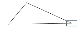
Rotary Engine
In a rotary engine, the slider is replaced by a piston and the link 1 by a cylinder pivoted at ‘O’.
Moreover, instead of one cylinder, seven or nine cylinders symmetrically placed at regular intervals in the same place or in parallel planes, are used.
All the cylinders rotate about the same fixed centre and form a balanced system. The fixed link 2 is also common to all cylinders.
Thus, in a rotary engine, the crank 2 is fixed and the body 1 rotates whereas in a reciprocating engine (1st inversion), the body 1 is fixed and the crank 2 rotates
(c)Third Inversion:
Oscillating cylinder engine
Crank and slotted – lever mechanism
By fixing the link 3 of the slider – crank mechanism the third inversion is obtained (Fig. 1). Now the link 2 again acts as a crank and the link 4 oscillates.
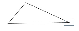
Figure: 3rd inversion of single slider – crank chain
Oscillating cylinder engine
As shown in below fig., the link 4 is made in the form of a cylinder and ‘a’ piston is fixed to the end of the link ‘1’. The piston reciprocates inside the cylinder pivoted to the fixed link 3.
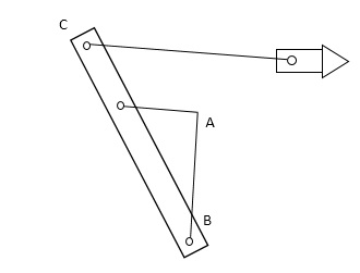
Figure: Oscillating cylinder engine
The arrangement is known as oscillating cylinder engine, in which as the piston reciprocates in the oscillating cylinder, the crank rotates.
Crank and slotted – lever Mechanism
If the cylinder of an oscillating cylinder engine is made in the form of a guide and the piston in the form of a slider, the arrangement as shown in Fig is obtained.
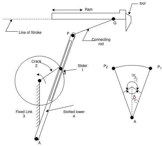
As the crank rotates about ‘A’, the guide 4 oscillates about B. At a point ‘C’ on the guide, link 5 is pivoted, the other end of which is connected to the cutting tool through a pivoted joint.
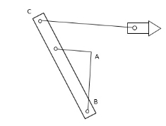
Figure: crank and slotted – lever mechanism
The extreme positions of the oscillating guide 4. The time of the forward stroke is proportional to the angle  whereas for the return stroke, it is proportional to angle
 , provide the crank rotates clockwise.
Comparing a crank and slotted – lever quick – return mechanism with a Whitworth quick – return mechanism, the following observations are made:-
Crank 3 of the Whitworth mechanism is longer than its fixed link 2 whereas the crank 2 of the slotted lever mechanism is shorter than its fixed link 3.
Coupler link 1 of the Whitworth mechanism maker compete rotations about its pivoted joint ‘O’ with the fixed link. However, the coupler link 4 of the slotted lever mechanism oscillates about its pivot B.
The coupler link holding the tool can be pivoted to the main coupler link at any convenient point ‘C’. In both cases. However, for the same displacement of the tool, it is more convenient if the point ‘C ’ is taken or the extension of the main coupler link (towards the pivot with the fixed link) in case of the Whitworth mechanism and beyond the extreme position of the slide in the slotted – lever mechanism.
(d) Fourth Inversion:
Hand Pump
If the link ‘4’ of the slider – crank mechanism is fixe, the fourth inversion is obtained.
Link 3 can oscillate about the fixed pivot ‘B’ on the link 4. This makes the end A of the link 2 to oscillate about ‘B’ and the end ‘O’ to reciprocate along the axis of the fixed link 4.
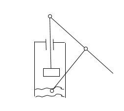
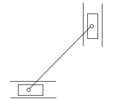
Figure : Hand pump
Above figure shows a hand – pump. Link 4 is made in the form of a cylinder and a plunger fixed to the link 1 reciprocates in it.
Key takeaway: There are basically four inversions of slider crank chain as first, second, third and fourth inversion with examples.
1.10.3 Inversion of Double slider crank chain
A four – bar chain having two turning and two sliding pairs such that two pairs of the same kind are adjacent is known as a double slider – crank chain (Fig. 18)
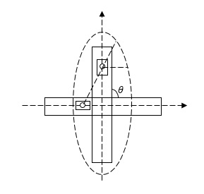
Figure : Double slider crank chain
(a) First Inversion:
Elliptical trammel
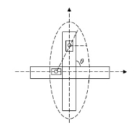
Figure : Elliptical trammel
This inversion is obtained when the link 1 is fixed and the two adjacent pairs 2 – 3 and 3 – 4 are turning pairs and the other two pairs 1 – 2 and 4 – 1 sliding pairs.

If P is mid-point of link AB, then AP = BP.

Above Fig. shows an elliptical trammel in which the fixed link 1 is in the form of guides for slider 2 and 4.
With the movement of the sliders, any point C on the link 3, except the midpoint of AB will trace an ellipse on a fixed plate. The midpoint of AB will trace a circle.
Let at any instant, the link 3 make angle  with the x – axis. Considering the displacements of the sliders from the centre of the trammel,

 &
&

Squaring and adding
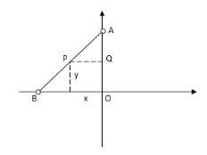

This is the equation of an ellipse. Therefore, the path traced by c is an ellipse with the semi. Major and semi – minor axes being equal to AC and BC respectively.
When C is the midpoint of AB: AC = BC, and

Which is the equation of a circle with AC (=BC) as the radius of the circle.
(b) Second Inversion
Scotch Yoke
A scotch yoke mechanism is used to change the rotary motion into a sliding motion. As the crank 3 rotates, the horizontal portion of the link 1 slides or reciprocates in the fixed link 4.
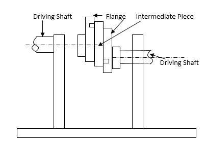
Figure: scotch yoke mechanism
(c)Third Inversion:
This inversion is obtained when the link 3 of the first inversion is fixed and the link 1 is free to move.
The rotation of the link 1 has been shown in fig. in which the full lines show the initial position. With rotation of the link 4 through 45o in the clockwise direction, the link 1 and 2, rotate through the same angle whereas the midpoint of the link 1 rotates through 90o in a circle with the length of link 3 as diameter. Thus, the angular velocity of the midpoint of the link 1 is twice that of links 2 and 4.
The sliding velocity of the link 1 relative to the link 4 will be maximum when the midpoint of the link 1 is at the axis of the 4. In this position, the sliding velocity is equal to the tangential velocity of the midpoint of the link 1.
Max. Sliding velocity = tangential velocity of midpoint of the link 1
= angular velocity of midpoint of the link 1 x radius
The sliding velocity of the link 1 relative to the link 4 is zero when the midpoint of 1 is on the axis of the link 2.
Application
Oldham’s coupling
If the rotating links 2 and 4 of the mechanism are replaced by two shafts, one can act as the driver and the other as the driven shaft with their axes at the pivots of links 2 and 4.
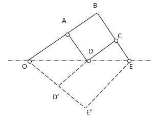
Figure: Oldham’s coupling
Above Figure shows an actual Oldham’s coupling which is used to connect two parallel shaft when the distance between their axes is small. The two shafts have flanges at the ends and are supported in the fixed bearings representing the link 3. In the flange 2, a slot is cut in which the tongue x of the link 1 is fitted and has a sliding motion. Link 1 is made circular and has another tongue r at right angles to the first and which fits in the recess of the flange of the shaft 4. Thus, the intermediate link 1 slides in the two slots n the two flanges while having the rotary motion.
Maximum sliding velocity = Peripheral velocity along the circular path
= angular velocity of shaft distance between shafts.
Mechanisms with lower pairs
When two elements of a pair have a surface contact and a relative motion takes place, the surface of one element slides over the surface of the other, the pair formed is known as lower pair.
Pantograph
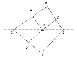
Figure: Pantograph
A pantograph is an instrument used to reproduce to an enlarged or a reduced scale and as exactly as possible the path described by a given point.
It consist of a jointed parallelogram ABCD as shown in fig. It is made up of bars connected by turning pairs. The bars BA and BC are extended to O and E respectively such that –

Thus for all relative positions of the bars, the triangles OAD and OBE are similar and the points O, D and E trances out the same path as described by point D.
From similar triangles OAD and OBE, we find that

Let point O be fixed and the points D and E move to some new positions D’ and E’. Then
A pantograph is most common device used for the reproduction of plane areas and figures such as maps, plans, etc. on enlarged or reduced scales. It is sometimes, used as an indicator rig. In order to reproduce to a small scale the displacement of the crosshead and therefore of the piston of a reciprocating steam engine. It is also used to guide cutting tools. A modified form of pantograph is used to collect power at the top of an electric locomotive.
The identification of velocity of one or more point on a link is very important in mechanism design. Ften times it occurs that synchronous motion is needed between two mechanisms such in the box packing system where boxes are filled at a certain rate and as a conaequence of that packing mechanism must adopt the rate. In the other case, like reciprocating motion of of a slider inertial forces upon changes in direction must be minimized otherwise it could be in the long or short range.
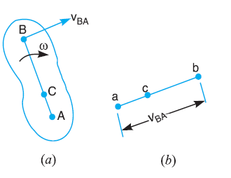
Consider two points A and B on a rigid link AB, as shown in Figure. One of the extremities (B) of the link move relative to A, in a clockwise direction. Since the distance from A to B remains the same. It is thus obvious, that the relative motion of B with respect to A must be perpendicular to AB. According to velocity method:
Velocity of any point on a rigid link with respect to another point on the same link is always perpendicular (⟘) to the line joining these points on the configuration (or space diagram).
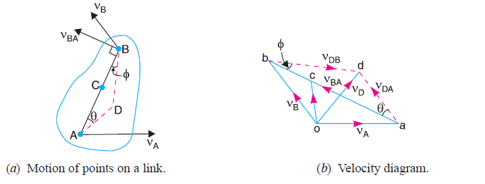
The relative velocity of B with respect to A (i.e. vBA) is represented by the vector ab and is perpendicular to the line AB as shown in Figure (b).
Consider two points A and B on a link as shown in Figure (a)
1- Let the absolute velocity of the point A i.e. vA is known in magnitude and direction
2-The absolute velocity of the point B i.e. vB is known in direction only
3- Then the velocity of B may be determined by drawing the velocity diagram as shown in Figure (b)
The velocity diagram is drawn as follows:
5. Measure ob, which gives the required velocity of point B ( vB), to the scale
The absolute velocity of any point C on AB may be determined by dividing vector ab at c in the same ratio as C divides AB in Figure (a).In other words:
Vel. of C rel. to A = Vel. of C rel. to B + vel. of B rel. to A = Vel. of C rel to D
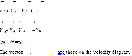
Fig.:Four link mechanism
VcaVcbVbaVcd
dc bc ab
ac bcbc
Vbaor ab = ω.AB;to AB
Vcb or bc is unknown in magnitude;to BC.
Vcd or dc is unknown in magnitude; to DC.
Intermediate point:
be BE
For point E on the link BC ,bc , ae represents the absolute velocity of E.

 Offset point:
Write the vector equation for point F,
V fb is=BF; draw a line perpendicular BF through b.
V fc is=CF; draw a line perpendicular to CF through c.
The intersection of the two lines locates the point f. af indicates the velocity of F relative to A or absolute velocity of F.
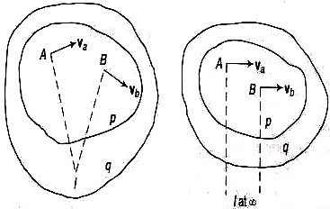
The intersection point of two different lines is called instantaneous center of rotation (I – center). An I – center is a center of rotation of a moving body relative to another body. It is named as Ipq and it will be in ascending order of the alphabets or digits.
Number of I–centers in a mechanism=N=n( n-1 )/2
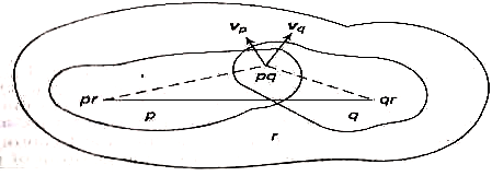
Kennedy’s theorem:
If three plane bodies have relative motion among themselves, their I‒center must lie on a straight line.

Fig.: Kennedy Theorem
Locating I‒centers:
A four‒link mechanism ABCD has 4 links named 1,2,3,4. The number of I‒centers is
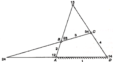
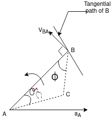
Fig: I center
I‒center 12 and 14 are fixed I‒centers.
I‒center 23 and 34 are permanent but not fixed I‒centers.
I‒center 13 and 24 which are neither fixed nor permanent can be located easily by applying Kennedy’s theorem as explained below.
I‒center 13:
As the three links 1, 2, 3 have relative motions among themselves, their I‒centers lie on a straight line. Thus I‒center 13 lies on the line joining 12 and 23.
Similarly I‒center 13 lies on the line joining 14 and 34. The intersection of the two lines locates the I‒center 13.
I‒center 24: Considering two sets of links 2, 1, 4 and 2, 3, 4, the I‒center would lie on the lines 12‒14 and 23‒34. The interaction locates the I‒center 24.
Rules to Locate I‒centers by inspections:
Key takeaway: Kennedy’s thorem is quite important which relates the relative motion and location of instantaneous centre.
The rate of change of velocity with respect to time is known as acceleration and acts in the direction of the change in velocity. A change in the velocity requires any of the following conditions to be fulfilled.
Consider two points A and B on the rigid link. Let the acceleration of the point A that is aA is known in magnitude and direction of path of B is given.
The acceleration of the point B is determined in magnitude and direction by drawing the acceleration diagram.

2. We know that the acceleration of B with respect to A that aBA has the following two components:
1. Radial component of acceleration of B with respect to A that is arBA
2. Tangential component of the acceleration B with respect to A that is atBA
3. Draw vector a’x parallel to the link AB, such that
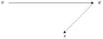
4. By joining the points a’ and b’ we may determine the total acceleration of B with respect to A that is aBA. The vector a’b’ is known as acceleration image of the link AB
Acceleration:
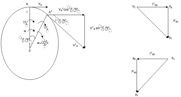
Let a link OA, of length r, rotate in a circular path in the clockwise direction as shown in figure. It has instantaneous angular velocity ω and an angular acceleration α in the same direction, i.e., the angular velocity increases in the clock wise direction. Tangential velocity of A ,va= ωr . In short interval of time δt,let OA assume the new position OAʹ by rotating through a small angle δθ .
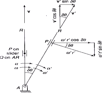
Fig.: Acceleration Diagram
Angular velocity of OA′ ,ωa′ =ω+α·δt .
Tangential velocity of A′, Va′ =(ω+α·δt)r .
The tangential velocity of A′ may be considered to have two components;
Oneperpendicular to OA and the other parallel to OA .
Change of velocity perpendicular to OA:

Velocity of Ato OA = Va
Velocity of Aʹ to OA =Vaʹ cos δθ
Change of velocity = Vaʹ cos δθ – Va
Acceleration of Ato OA=tr cosrt
In the limit, as δt→0, cos δθ→1

This represents the rate of change of velocity in the tangential direction of the motion of A relative to O and thus is known as the tangential acceleration.
Coriolis component of acceleration comes into existence only if there persists two coincident points that have linear relative velocity of angular motion and sliding about fixed finite centres of rotation.
Suppose the link AR is rotating about a fixed-point A on it. P is a point on a slider on the link. At any given instant, Let
ω = Angular velocity of the link
α = Angular acceleration of the link
v = Linear velocity of the slider on the link
f = Linear acceleration of the slider on the link
r = Radial distance of point P on the slider
In a very short interval of time δt let δθ be the angular displacement of the link and δr the displacement of the slider in the outer direction. After the shorter interval of time δt , let
ω′ = ω + α ∙ δt= angular velocity of the link.
v′ = v + f∙ δt= Linear velocity of the slider on the link.
r′ =r + δr= Radial distance of the slider.
Acceleration of P Parallel to AR:
Initial velocity of p along AR = v = vpq
Final velocity of p alongAR = v′cosδθ ‒ ω′r′sinδθ Change ofvelocity along AR = (v′ cos δθ ‒ ω′r′sinδθ) ‒ v
Acceleration of P along AR=vftcostrrsinv
t
In the limit, as δt →0, cos δθ → 1 and sin δθ → δθ
 Acceleration of P along AR= frddt
f r
f ‒ ω2r
Acc. of slider – cent.acc.
This is the acceleration of P along AR in the radially outward direction.
Acceleration of P perpendicular to AR:
Initial velocity of P to AR = ωr
Final velocity of P to AR = v′sinδθ + ω′r′ cos δθChange of velocityto AR = (v′sinδθ + ω′r′cosδθ) ‒ωr
vω + ωv +αr
2ωv+ αr
The component 2ωv is known as the Coriolis acceleration component. It is positive if
rotating the radial velocity vector v through 900 in the direction of rotation of the link.
Coriolis component exist only if there are two coincident points which have,(i) linear relative velocity of sliding and, (ii) angular motion about fixed finite centers of rotation.
Let Q be a point on the link AR immediately beneath the point P at the instant, then,
Acc. Of P = Acce. Of P || to AR + Acceleration of Pto AR.
f pa( f 2 r)(2v r)
= f r2 r 2v
=Acc. of P rel. to Q + Acc. of Q rel to A + coriolis acceleration component
= f pq' f qa f cr
Sometimes for sake of simplicity, it is convenient to associate the Coriolis acceleration component fcr with fpq' and writing the equation in the form,
= fpq'fcrfqa
The crank and slotted lever mechanism is a quick return mechanism that converts rotary motion into linear motion. It is extensively used in shaping and cutting machines and particularly used in cutting flat surfaces out of metal stock. The return stroke of the ram is faster than the advancing stroke. This mechanism consists of an arm attached to a rotating disc that moves at a controlled uniform speed. Unlike the crank, the arm of the mechanism runs at different rate than the disc. By having the disc run at different than the attached arm, productivity increases because the amount of time needed for a cut is reduced.
This mechanism was invented by Whitworth in 1800s. It played an active role in increasing productivity by reducing cutting times in shaping machine.
Fig.: Crank and slotted lever mechanism
References:
1. Ghosh Malik, Theory of Mechanism and Machines, East-West Pvt. Ltd.
2. Hannah and Stephans, Mechanics of Machines, Edward Arnolde Publication.
3. R L Norton, Kinematics and Dynamics of Machinery, First Edition, McGraw Hill Education(India) P Ltd. New Delhi
4. Sadhu Singh, Theory of Machines, Pearson
5. D.K. Pal, S.K. Basu, Design of Machine Tools, Oxford &Ibh Publishing Co Pvt. Ltd.
6. Dr. V. P. Singh, Theory of Machine, Dhanpatrai and sons.
7. C. S. Sharma & Kamlesh Purohit, “Theory of Machine and Mechanism”, PHI.
8. D. Tripathy, Machine Dynamics.
