Unit -4
Balancing and Governors
It is the process of designing or modifying machinery, so that unbalance is reduced to an acceptable level and if possible is eliminated entirely.
4.2.1 Static Balance
Static Balancing: A system of rotating masses is said to be in static balance if the combined mass centre of the system lies on the axis of rotation. Net dynamic force acting on the system must be zero.
4.2.2 Dynamic Balance
Dynamic Balancing: A system of rotating masses is in dynamic balance when there does not exist any resultant centrifugal force as well as resultant couple. Net moments about any point in the plane must be zero.
Consider four masses of magnitude m1, m2, m3 and m4at distances of r1, r2, r3 and r4from the axis of rotating shaft. Let θ1, θ2, θ3, and θ4be the angles of these masses with the horizontal line OX as shown in fig. 1.Consider a disturbing mass  attached to a shaft rotating at
  rad/s as shown in Fig. Let
  be the radius of rotation of the mass
  (i.e. distance between the axis of rotation of the shaft and the centre of gravity of the mass
  ).
).
We know the centrifugal force exerted by the mass  on the shaft.

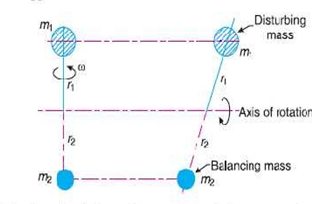
Fig. 1: Centrifugal force exerted by mass.
This centrifugal force acts radially outwards and thus produces bending moment on the shaft. In order to counteract the effect of this force, a balancing mass  may be attached in the same plane of rotation as that of disturbing mass
  such that centrifugal forces due to the two masses are equal and opposite.
Let  -- Radius of rotation of the balancing mass
  (i.e. distance between the axis rotation of the shaft and the centre of gravity of mass
  ).
).
Centrifugal force due to mass 

Equating 1 and 2

Key takeaway:
1. The product  may be split up in any convenient way. But the radius of rotation of the balancing mass (
 ) is generally made large in order to reduce the balancing mass
2. The centrifugal forces are proportional to the product of the mass and radius of rotation of the respective masses, because  is same for each mass.
We have discussed in the previous article that by introducing a single balancing mass in the same plane of rotation as that of disturbing mass, the centrifugal forces are balanced. in other words the two forces are equal in magnitude and opposite in direction. But this type of arrangement for balancing gives rise to a couple which tends to rock the shaft in its bearings. Therefore in order to put the system in complete balance, two balancing masses are placed into different planes, parallel to the plane of rotation of the distributing mass, in such a way that they satisfy the following two conditions of equilibrium.
The condition 1 and 2 together give dynamic balancing. The following two possibilities may arise while attaching the two balancing masses:
We shall now discuss both the above cases one by one.
The plane of the disturbing mass may be in between the planes of the two balancing masses:
Let
 = Distance between the planes A and L,
 =Distance between the planes A and M and
L=Distance between the planes L and M
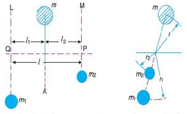
Fig. 2.Two plane balancing
We know that the centrifugal force exerted by the mass m in the plane A,

Similarly, the centrifugal force exerted by the mass  in the plane L,

And, the centrifugal force exerted by the mass  in the plane M,

Since the net force acting on the shaft must be equal to zero, therefore the centrifugal force on the disturbing mass must be equal to the sum of the centrifugal forces on the balancing masses, therefore


Similarly, m order to find the balancing force in plane M (or the dynamic force at the bearing P of the shaft) take moments about Q which is the point of intersection of the plane L and the axis of rotation. Therefore


Key takeaway: It may be noted that equation (i) represents the condition for static balance, but in order to achieve dynamic balance, equations (ii) or (iii) must also be satisfied
2. When the plane of the disturbing mass lies on one end of the planes of the balancing masses

Fig.3: Disturbing mass lying in one end of the plane
In this case, the mass m lies in the plane A and balancing masses lie in the planes L and M, as shown in Fig 21.3 As discussed above, the following conditions must be satisfied in order to balance the system i.e.


Now to find the balancing forces in the plane L (or the dynamic force at the bearing Q of a shaft) take moments about P which is the point of intersection of the plane M and the axis of rotation.
The magnitude and position of the balancing mass may be found out analytically or graphically as discussed below:
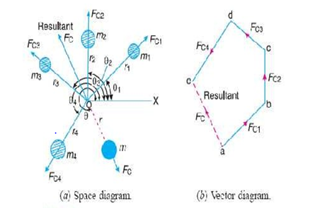
Fig. 4: Magnitude and direction of balancing mass
Analytical Method
The magnitude and direction of the balancing mass may be obtained, analytically as discussed below:
1. First of all, find out the centrifugal force (or the product of the mass and its radius of rotation ) exerted by each mass on the rotating shaft.
Consider any number of masses (say four) of magnitude  at distances of
  from the axis of the rotating shaft. Let
  be the angles of these masses with the horizontal line OX, as shown in Fig. Let these masses rotate about an axis through O and perpendicular to the plane of paper, with a constant angular velocity of
  .
.
2. Resolve the centrifugal forces horizontally and vertically and find their sums i.e.  . We know that
Sum of horizontal components of the centrifugal forces

And sum of vertical components of the centrifugal forces.

3. Magnitude of the resultant centrifugal force,

4. If  is the angle, which the resultant force makes with the horizontal then

5. The balancing force is then equal to the resultant force, but in opposite direction.
6. Now find out the magnitude of the balancing mass, such that

Where m=Balancing mass, and
R= Its radius of rotation
Graphical method
The magnitude and position of the balancing mass may also be obtained graphically as discussed below as:


 Resultant centrifugal force
m.r=Resultant of 
Key takeaway:
For analytical method  and
and  formulas are main formulas while solving of a problem.
For graphical method,  Resultant centrifugal force
Mass balancing encompasses a wide array of measures employed to obtain partial or complete compensation for the inertial forces and moments of inertia emanating from the crankshaft assembly. All masses are externally balanced when no free inertial forces or moments of inertia are transmitted through the block to the outside. However, the remaining internal forces and moments subject the engine mounts and block to various loads as well as deformities and vibratory stresses. The basic loads imposed by gas-based and inertial forces.
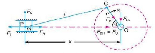
Primary and secondary unbalanced forces of reciprocating parts:.
Fig. 5: Unbalanced force of a reciprocating parts
Let m- Mass of the reciprocating parts,
L=Length of the connecting rod PC,
R= Radius of the crank OC,
 Angleof inclination of the crank with the line of stroke PO,
 =Angular speed of the crank.
 Ratio of length of the connecting rod to the crank radius =1/r
We have already discussed in Art 15.8 that the acceleration of the reciprocating of the reciprocating parts is approximately given by the expression

Inertia force due to reciprocating parts or force required to accelerate the reciprocate
Parts

We have discussed in the previous article that the horizontal component of the force exerted on the crank shaft bearing is equal and opposite to inertia force. This force is an unbalanced one and is denoted by  .
.
Unbalanced force,

The expression ( ) is known as primary unbalanced force and (
 ) is called secondary unbalanced force.
4.6.1 Variation in Tractive force: The resultant unbalanced force due to the two cylinders along the line of stroke is known as tractive force.
Consider the crank of first cylinder be inclined at an angle θ with the line of stroke. The second cylinder has the crank at right angle to the first crank so the angle of inclination for the second crank becomes (90+θ).
4.6.2: Swaying Couple: The unbalanced forces along the line of stroke for the two cylinders constitute a couple about the centre line between the cylinders.
The couple trends to sway the engine alternatively in clockwise and anticlockwise directions. Hence, the couple is known as swaying couple.
The unbalanced forces along the line of stroke for the two cylinders constitute a couple about the centre line YY between the cylinders as shown in Fig. 22.5
This couple has swaying effect about the vertical axis and tends to sway the engine alternately in clockwise and anticlockwise directions. Hence the couple is known as swaying couple.
Let
A=Distance between the centre lines of the two cylinders
Swaying couple


The swaying couple is maximum or minimum when  is maximum or minimum For
  to be maximum or minimum,


Thus the swaying couple is maximum or minimum when 
Maximum and minimum value of the swaying couple,

4.6.3 Hammer Blow:
The maximum magnitude of the unbalanced force along the perpendicular to the line of stroke is known as hammer blow.
The unbalanced force along the perpendicular to the lie of stroke is due to the balancing mass B, at the radius b, in order to balance reciprocating parts only a force is  is required.The quantity
 will be maximum for sin θ =1, θ=990 or 2700
Net pressure between the wheel and the rail

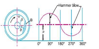
Fig. 6: Net Pressure graph between wheel and rail
If  is negative then the wheel will be lifted from the rails. Therefore, the limiting condition in order that the wheel does not lift from the rails is given by

And the permissible value of the angular speed,

There are basically two types of governors -
(1) Centrifugal Governors and
(2) Inertia Governors
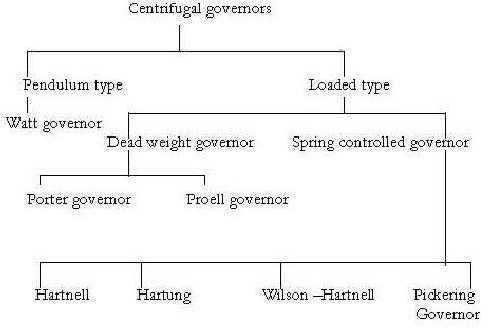
Key Takeaway: The major classification of governor is the centrifugal and inertia governor which is having further other classifications as gravity controlled and spring controlled governor.
It is known as centrifugal governor because it is based on the balancing of centrifugal force on the rotating balls by equal and opposite force that is controlling force.
It works on centrifugal effects produced by rotating balls. As a speed of balls increases, the balls tend to rotate at a greater radius from the spindle axis.
This results into movement of sleeve to upward direction and this movement is attached to the throttle through a bell crank lever and it closes the throttle valve to required extent.
When speed of ball decreases, the balls tend to rotate at a smaller radius and valve is opened according to requirement.
Characteristics of centrifugal Governor
It is the vertical distance between the centre of the governor halls and the point of intersection between the upper arms on the axis of spindle is known as governor height. It is generally denoted byh.
2. Sleeve lift
The vertical distance the sleeve travels due to change in the equilibrium Speed is called the sleeve lift. The vertical downward travel may be termed as Negative lift
3. Isochronism
This is an extreme case of sensitiveness. When the equilibrium speed is constant for all radii of rotation of the balls within the working range, the governor is said to be in isochronisms. This means that the difference between the maximum and minimum equilibrium speeds is zero and the sensitiveness shall be in infinite.
4. Stability
Stability is the ability to maintain a desired engine speed without Fluctuating. Instability results in hunting or oscillating due to over correction. Excessive stability results in a dead-beat governor or one that does not correct sufficiently for load changes. A governor is said to be unstable, if the radius of rotation decreases as the speed increase.
Sensitiveness
A governor is called sensitive when it readily responds to a small change of speed.
It is defined as the difference between maximum and minimum speeds to mean equilibrium speed.
If, N= (N1+N2)/2, Mean speed
N1= Minimum speed corresponding to full load conditions, and
N2= Maximum speed corresponding to no load conditions.
Sensitiveness= (N2-N1)/N
Gravity controlled centrifugal governors are the governors are the governors which regulate the speed of an engine when there is variation in the load by using gravity of the earth as a major component. In this type of governor, central load is attached through the sleeve, which slides on the spindle. There is force of friction between the loaded sleeve and the spindle.
4.10.1 WATT GOVERNOR:
The simplest form of a centrifugal governor is a Watt governor, as shown in fig. It is basically a conical pendulum with links attached to a sleeve of negligible mass. The arms of the governor may be connected to the spindle in the following three ways:
The pivot P, may be on the spindle axis as shown in fig. (a)
The pivot P, may be offset from the spindle axis and the arms when produced intersect at O, as shown in Fig (b)
The pivot P, may be offset but the arms cross the axis at O, as shown in Fig. (c)
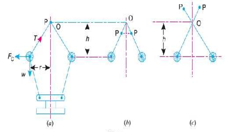
Fig. 7: Watt governor
Let m=Mass of the ball in kg.
W=Weight of the ball in Newton=m.g
T=Tension in the arm in Newton
 =Angular velocity of the arm and ball about the spindle axis in rad/s.
r=Radius of the path of rotation of the ball i.e. horizontal distance from the centre of the ball to the spindle axis in Metre,
 --- Centrifugal forces acting on the ball in Newton -m,
 , r and
 Height of the governor in metre
It is assumed that the weights of the arms, links and the sleeve are negligible as compared to the weight of the balls. Now, the ball is in equilibrium under the action of
Centrifugal force acting on the ball
The tension in the arm
The weight of the ball
Taking moments about point O, we have


When g is expressed in m/s^2 and  in rad/s then h is in meters. If N is the speed in r.p.m. then


Key takeaway:
We see from the above expression that the height of a governor h is inversely proportional to N^2. Therefore at high speeds, the value of h is small.
At such speeds, the change in the value of each corresponding to a small change in speed is insufficient to enable a governor of this type to operate the mechanism to give the necessary change in the fuel supply.
The governor may only work satisfactorily at relatively low speeds i.e. from 60 to 80 r.p.m.
Limitations of watt governor:
(1) It is limited to vertical positions applications.
(2) It is used in very slow speed engine. At higher speed, the sensitivity will decrease.
4.10.2 Porter Governor
The porter governor is a modification of a Watts governor with Central load attached to the sleeve as shown in figure (a) . The load moves up and down the central spindle. the additional downward force increases the speed of revolution required to enable the balls to rise to any predetermined level.
Consider the forces acting on one half of the governor as shown in figure (b)
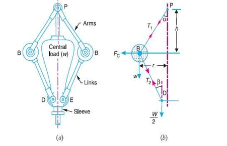
Fig. 8: Porter Governor
Let m= mass of each ball in kg
w=weight of each ball in Newton’s=m.g
M=mass of the central load in kg.
W=weight of the central load in Newton’s=M.g
r=radius of rotation in metres
h=height of governor in metres
N=speed of the balls in r.p.m.
 =angular speed of the ball is in rad/s
=2ΠN/60 rad/s
 =centrifugal force acting on the ball in Newton’s=
 =force in the arm in Newtons
 =force in the link in Newtons
 =Angle of inclination of the arm to the vertical
 =Angle of inclination of the link to the vertical.
4.10.3 Proell Governor
The Proell governor has the balls fixed at B and C to the extension of the links DF and EG as shown in Fig. The arms FP and GQ are pivoted at P and Q respectively.
Consider the equilibrium of the forces on one half of the governor as shown in Fig (b).
The instantaneous centre lies on the intersection of the line PF produced and the line from D drawn perpendicular to the spindle axis. The perpendicular BM is drawn on ID.
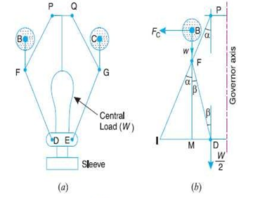
Fig.9: Proell Governor
Spring Controlled Governor:
In this type of centrifugal governor, a helical spring or several other springs are utilized to control the movement of the sleeve or balls. These governors are comparatively smaller in size.
4.10.4 Hartnell Governor:
A Hartnell governor is a spring loaded governor as shown in figure. It consists of two Bell crank lever pivoted at the points O,O to the frame. The frame is attached to the governor’s spindle and therefore rotates with it. Each liver carries a ball at the end of the vertical arm OB and ruler at the end of the horizontal arm OR. A helical spring in compression provides equal downward forces on the two rollers through a caller on the sleeve. The spring force may be adjusted by screwing a nut up or down on the sleeve.
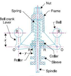
Fig. 10: Hartnell Governor
Let m=mass of each ball in kg.
M=mass of sleeve in kg
 =minimum radius of rotation in metres
 =maximum radius of rotation in metres
 = Angular speed of the governor at minimum radius in rad/s
 =Angular speed of the governor at maximum radius in rad/s
 =spring force exerted on the sleeve at
 in Newtons,
 =spring force exerted on the sleeve at
 in Newtons
 centrifugal force at
 in newtons =
 =centrifugal force at
 in newtons =
s= stiffness of the spring or the force required to compress the spring by one mm,
x=length of the vertical or ball arm of the lever in metres.
y=length of the horizontal or sleeve arm of the lever in metres,
r=distance of fulcrum O from the governor Axis are the radius of rotation when the governor is in mid position in metres.
The phenomenon of continuous fluctuation of the engine speed above and below the mean speed is termed as hunting. This occurs in over-sensitive or isochronous governors. Suppose an isochronous governor is fitted to an engine running at a steady load. With a slight increase of load, the speed will fall and the sleeve will immediately fall to its lowest position. This shall open the control valve wide and excess supply of energy will be given, with the result that the speed will rapidly increase and the sleeve will rise to its higher position. As a result of this movement of the sleeve, the control valve will be cut off; the supply to the engine and the speed will again fall, the cycle being repeated indefinitely. Such a governor would admit either more or less amount of fuel and so effect would be that the engine would hunt.
It is known as inertia governor because balls change their position due to centrifugal forces and forces are set up by an angular acceleration or deceleration of the given spindle
Expression for moment of inertia of inertia governor-
Let, r=radial distance, ῳ= Angular velocity of disc, and v=Tangential velocity=rῳ
Centrifugal force on on rotating mass, Fc=mrῳ2
Therefore, Fi=mf=m(dv/dt), where Fi= inertia force.
The effort of governor is the mean force acting on the sleeve to raise or lower it for a given change of speed. At constant speed, the governor is in equilibrium and the resultant force acting on the sleeve is zero.
However, when the speed of the governor increases or decreases, a force is exerted on the sleeve which tends to move it. When the sleeve occupies a new steady position, the resultant force acting on it again becomes zero.
If the force acting at the sleeve changes gradually from zero to value E for an increased speed of the governor, the mean force or the effort is E/2
E=cg/1+k [2m+M(1+k)]
Power of a governor is the work done at the sleeve for a given percentage change of speed that is it is the product for the effort and the displacement of the sleeve.
Power=E/2(2*Height of Governor)
Key takeaway: Effort of the governor is given by formula E=cg/1+k [2m+M(1+k)] and power is mentioned by formula Power=E/2(2*Height of Governor)
References
1. Ghosh Malik, Theory of Mechanism and Machines, East-West Pvt. Ltd.
2. Hannah and Stephans, Mechanics of Machines, Edward Arnolde Publication.
3. R L Norton, Kinematics and Dynamics of Machinery, First Edition, McGraw Hill Education(India) P Ltd. New Delhi
4. Sadhu Singh, Theory of Machines, Pearson
5. D.K. Pal, S.K. Basu, Design of Machine Tools, Oxford &Ibh Publishing Co Pvt. Ltd.
6. Dr. V. P. Singh, Theory of Machine, Dhanpatrai, and sons.
7. C. S. Sharma & Kamlesh Purohit, “Theory of Machine and Mechanism”, PHI.
8. Mr. C. Ravindran, Department of Mechanical Engineering S.C.E, Vijayamangalam.
