Unit -5
Brake and Dynamometers and Gyroscope
Friction
When two bodies have relative motion between each other, a force acts in the opposite direction of their relative motion, which opposes their motion. This force is called friction force.
Friction force arises due to the relative motion between two bodies and hence some energy is wasted in overcoming the friction.
Classification of friction
(a) Static friction: When body is at rest, the friction acts on the on the body is called static friction.
(b) Dynamic Friction: When body is in motion, the friction acts on the body is called dynamic friction. It is also known as kinetic friction and it is always less than the static friction.
(c) Dry friction: When two dry and unlubricated surfaces are in contact, the friction acts between them is called dry friction. Sliding friction and rolling friction are examples of dry friction.
(d) Boundary or greasy friction: When the two rubbing surfaces are separated by a very thin layer of lubricant, the friction is known as boundary friction.
(e) Film friction: When the two surfaces is in contact are completely separated by a lubricant, friction will occur due to shearing of different layers of the lubricant. This is known as film friction or viscous friction.
Components of friction
1. Limiting friction: It is the maximum value of friction between two surfaces after which motion of body occur.
2. Co-efficient of friction: It is defined as the ratio of limiting friction force to the normal reaction. Mathematically, µ=F/N.
3. Angle of friction: This is the angle between the resultant reaction and normal to the plane on which motion of the other.
4. Angle of repose: Limiting angle up to which the body remains at the rest or just about to move in absence of external force is called angle of repose. The body will begin to move down the plane when the angle of inclination of the plane is equal to the angle of friction.
5.2.1 Laws of Friction
F/N= constant
2. Laws of Kinetic friction: The friction force always acts in the direction opposite to that in which the body is moving. The magnitude of the kinetic friction bears a constant ratio to the normal reaction between the two surfaces. But the ratio is slightly less than that in case of limiting friction. For moderate speeds, the force of friction remains constant but it decreases with increase in speed.
3. Laws of solid friction: The force of friction is directly proportional to the normal load between the surfaces. The friction force does not depend upon the area of contact surface. Friction depends upon the material of which the contact surfaces are made. Friction does not depend upon the sliding velocity of one body relative to the other.
4. Laws of fluid friction: The friction force is almost independent of the load. With increase of the temperature of the lubricant, the friction force reduces. Friction does not depend upon the substance of the materials. Friction differs from one lubricant to other.
Key takeaway: There are basically four laws of friction and they are, law of static friction, law of kinetic friction, law of solid friction and law of fluid friction.
5.2.2 Types of Lubrication
Lubrication is the admittance of lubricating oil between two surfaces having relative motion in order to reduce friction between them and to ensure smooth running.
There are basically four types of Lubrication, mentioned below:
(a) Hydrodynamic Lubrication: It is type of lubrication where wedge shaped oil film is built up between the moving block and the surface. In other words, moving block acts as a pump to force oil into clearance that narrows down progressively as the block moves.
(b) Elastohydrodynamic Lubrication: When the load acting on the bearing is very high, the material itself deform elastically against the pressure built up of the oil film. This kind of lubrication is called as elastohydrodynamic lubrication. It happens usually between cam and followers, gear and teeth.
(c) Boundary Lubrication: If the film thickness between the two surfaces in relative motion becomes so thin that the formation of hydrodynamic oil film is not possible and the surface high spot penetrates this thin to make metal to metal contact then such lubrication is known as boundary lubrication. Such situation can occur due to high load, too thin oil and insufficient supply of oil due to low speed of movement.
(d) Hydrostatic Lubrication: In this lubrication, a thin oil film resists its instantaneous squeezing out under reversal of loads with relative slow motions.
Key takeaway: There are basically four categories of lubrication and they are mentioned as Hydrodynamic lubrication, Elastohydrodynamic lubrication, Boundary lubrication, and Hydrostatic lubrication.
A Brake is device by means of which artificial frictional resistance is applied to a moving machine member, in order retard or stop the motion of a machine. In the process of performing this function, the brake absorbs either kinetic energy of the moving member or potential energy given up by objects being lowered by hoists, elevators etc. The energy absorbed by brakes is dissipated in the form of heat. This heat is dissipated in the surrounding air (or water which is circulated through the passages in the brake drum) so that excessive heating of the brake lining does not take place. The Capacity of brake depends upon the following factors:
CLASSIFICATION
Air brakes are used in trucks, buses, trailers, and semi-trailers. George Westing house first developed air brakes for use in railway service. He patented a safer air brake on March 5, 1872.
Hydraulic brakes: The hydraulic brake is an arrangement of braking mechanism which uses brake fluid, typically containing ethylene glycol, to transfer pressure from the controlling unit. In 1918 Malcolm Lougheed developed a hydraulic brake system.
Electrical brakes: Electric brakes are used in electrically driven utilities and machines in industries and mainly in electric automotive such as electric locos.This was designed as an alternative to the conventional braking system of applying friction over the wheels to slow them.
Mechanical brakes: In mechanical brake friction force is applied by giving pressure on the surface of drum or disk. It may further divide axial brake and radial brake as per the direction of force acting on drum. Radial break may internal or external.

 Disc brakes: A brake disc is usually made of cast iron, reinforced carbon-carbon or ceramic matrix composites. This is connected to the wheel and/or the axle.To stop the wheel, friction material in the form of brake pads (mounted on a device called a brake caliper) is forced mechanically, hydraulically, pneumatically or electromagnetically against both sides of the disc.

Fig. 1: Short and long shoe brake
Key takeaway: Various geometric configuration of drum brakes are illustrated above Drum Brakes are classified based on the shoe geometry. Shoes are classified as being either short or long. A short shoe is one whose lining dimension in the direction of motion is so small that contact pressure variation is negligible.
Brake Material:
In a four wheeled moving vehicle, the brakes may be applied to
In all the above mentioned three types of braking, it is required to determine the retardation one of the vehicles when brakes are applied.
 Since the vehicle retards, therefore it is a problem of dynamics. But it may be reduced to an equivalent problem of statics by including the inertia force in the system of forces actually applied to the vehicle.The inertia force is equal and opposite of the braking force causing retardation.

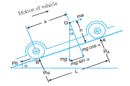
Fig.2: Motion of vehicle in up inclined plane and brakes are applied on the rear wheel only.
Let
 =Total braking force (in newtons) acting at the rear wheels due to the application of the brakes. Its maximum value is
  .
.
Resolving the forces parallel to the plane,

Resolving the forces perpendicular to the plan,

Taking moments about G, the centre of gravity of the vehicle,

Substituting the value of  and
and  [from equation (ii)]


Let
 Angle of inclination of the plane to the horizontal
m=Mass of the vehicle in kg
h=Height of the C.G. of the vehicle above the road surface in meters
x=Perpendicular distance of C.G. from the rear axle in meters.
L=Distance between the centres of the rear and front wheels (also called wheel base) of the vehicle in meters.
 =Total normal reaction between the ground and the front wheels in Newton.
 =Total normal reactions between the ground and the rear wheels in newtons
 =Coefficient of friction between the tyres and road surface, and
a=Retardation of the vehicle in m/s.
2. When the brakes are applied to front wheels only
Fig.3: Motion of vehicle in up inclined plane and brakes are applied on the front wheel only.

Fig.3: Motion of vehicle in up inclined plane and brakes are applied on the front wheel only.
It is very rare way of braking the vehicle, in which the braking force acts at the front wheels only.
Let  Total braking force (in newtons) acting at the front wheels due to the application of brakes. Its maximum value is
Resolving the forces parallel to the plane,

Resolving the forces perpendicular to the plane,

Taking moments about G, the centre of gravity of the vehicle,

Substituting the value of  [from equation (ii)]


And


We know from equation (i),


Note:
1 When the vehicle moves on a level track, then 

2. When the vehicle moves down the plane, the equation (i) become


It is a brake incorporating device to measure the frictional resistance applied. This is used to determine the power developed by the machine, while maintaining its speed at the rated value.
Rope Break Dynamometer:
It is form of absorption type Dynamometer which is most commonly used for measuring the brake power of the engine. It consists of one, two or more ropes wound around the fly wheel or rim of a pulley fixed rigidly to the shaft of an engine. The upper end of the ropes is attached to a spring balance while the lower end of the ropes is kept in position by applying a dead weight as shown in Fig. In order to prevent the slipping of the rope over the flywheel, wooden blocks are placed at intervals around the circumference of the flywheel.

Fig. 4: Rope brake Dynamometer
In the operation of the brake, the engine is made to run at a constant speed. The frictional torque, due to the rope, must be equal to the torque being transmitted by the engine.
Let,
W = Dead load in Newton.
S = spring balance reading in Newton.
D = Diameter of the wheel in Metre,
d = diameter of rope in metres, and
N = Speed of the engine shaft in r.p.m.
Net Load on the brake = (W-S) Newton
Distance move in one Revolution =П (D + d) Metres
Work done per revolution = (W –S) *(D+d) Metres
Work done per minute by N revolution = (W– S) x П (D + d) x N ….Nm /min
 Prony Brake Dynamometer:
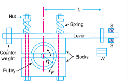
A simplest form of an absorption type dynamometer is a prony brake dynamometer. It consists of two wooden blocks placed around a pulley fixed to the shaft of an engine whose power is required to be measured.
The blocks are clamped by means of two bolts and nuts, as shown in Figure. A helical spring is provided between the nut and the upper block to adjust the pressure on the pulley to control its speed.
The upper block has a long lever attached to it and canies a weight W at its outer end.
A counter weight is placed at the other end of the lever which balances the brake when loaded.
Two stops S-S is provided to limit the motion of lever.
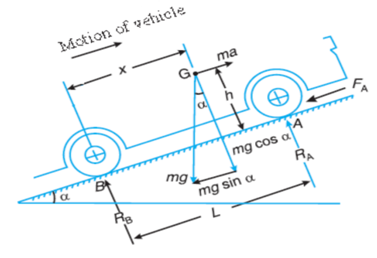
Fig.5: Prony Brake Dynamometer
Let W = weight of the outer end of the lever in newtons
L= horizontal distance of the weight W. from the centre of the pulley in meters.
F= frictional resistance between the blocks and the pulley in newtons.
R= radius of the pulley in meters, and
N = speed of the shaft in r.p.m
The moment of the frictional resistance or torque on the shaft.

Work done in one revolution
Torque * angle turned in radians

Work done per minute

Brake power of the engine


 Watts
Watts
Epicyclic-train Dynamometer:
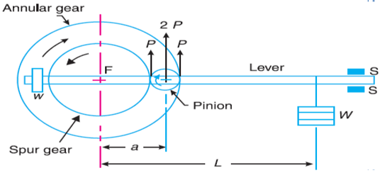
An epicyclic-train dynamometer consists of a simple epicyclic train of gears, i.e. a spur gear, an annular gear (a gear having internal teeth) and a pinion. The spur gear is keyed to the engine shaft and rotates in anticlockwise direction. The annular gear is also keyed to the driving shaft and rotates in clockwise direction. The pinion or the intermediate gear meshes with both the spur and annular gears. The pinion revolves freely on a lever which is pivoted to the common axis of the driving and driven shafts.
A weight w is placed at the smaller end of the lever in order to keep it in position. If the friction of the pinion which the pinion rotates is neglected, then the tangential effort P exerted by the spur gear on the pinion and the tangential reaction of the annular gear on the pinion are equal.
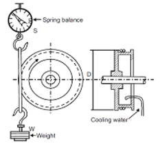
Fig. 6: Epicyclic train dynamometer
Since these efforts act in the upward direction as shown, therefore total upward force on the lever acting through the axis of the pinion is 2P.
This force tends to rotate the lever about its fulcrum and it is balanced by a dead weight W at the end of the lever. The stops S, S are provided to control the movement of the lever.
For equilibrium of the lever, taking moments about the fulcrum F.

Or 
Let
R = pitch circle radius of the spur gear in meters , and
N = speed of the engine shaft in r.p,m
Torque transmitted ,T=P.R
Power transmitted
 =
= Watts
Watts
The dynamometer in which the work is not absorbed in the process but it is utilised after the measurements is known as transmission type dynamometer and if the transmission is taking place by using belt, then it is considered as belt transmission Dynamometer.
One of the Belt transmission dynamometer is Froude or Thorneycroft transmission Dynamometer:
Froude or Throney croft Transmission Dynamometer:
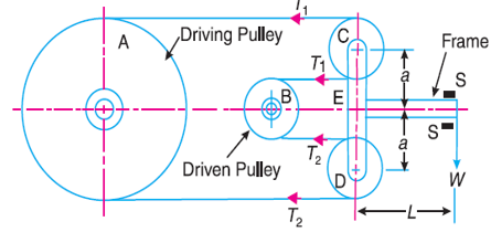
When the belt is transmitting power from one pulley to another, the tangential effort on the driven pulley is equal to the difference between the tensions in the tight and slack sides of the belt.

 A belt dynamometer is introduced to measure directly the difference between the tensions of the belt, while it is running. A Froude or Throneycroft transmission dynamometer consists of a pulley, a(driving pulley) which is rigidly fixed to the shaft of an engine whose power is required to be measured. There is another pulley B (driven pulley) mounted on another shaft to which the power from pulley A is transmitted.

Fig. 7: Froude or Throney croft dynamometer.
The pulleys A and B are connected by means of a continuous belt passing round the two loose pulleys C and D which are mounted on a T-shaped frame.
A torsion dynamometer is used for measuring large powers particularly the power transmitted along the propeller shaft of a turbine or motor vessel.
A little consideration will show that when the power is being transmitted, then the driving end of the shaft twists through a small angle relative to the driven end of the shaft. The amount of twist depends upon many factors such as torque acting on the shaft (J), length of the shaft (l), diameter of theshaft (D) and modulus of rigidity (C) of the material of the shaft.
The torsion equation is,

J = Polar moment of inertia of shaft, θ= twist angle in radians
For a solid shaft of diameter D, the polar moment of inertia = 
And for a hollow shaft of external diameter D and internal diameter d,

From the above torsion equation

Where k = C.J / l is a constant for a particular shaft.
Thus, the torque acting on the shaft is proportional to the angle of twist. This means that if the angle of twist is measured by some means, then the torque and hence the power transmitted may be determined.

The power transmitted,
Since the angle of twist is measured for a small length of the shaft, therefore some magnifying device must be introduced in the dynamometer for accurate measurement.
Question: In a laboratory experiment, the following data was recorded with rope brake.
Diameter of the fly wheel 1.2 m, diameter of the rope 12. 5 mm, speed of the engine 200 r.p.m , dead load on the brake 600N : spring balance reading 150N Calculate the brake power of the engine.
Solution:- given D= 1.2 m ; d=12.5 mm =0.0125 m; N= 200 r.p.m ; W= 600N ; S=150N
B.P =

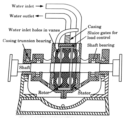
Hydraulic accumulator works on the principle of dissipating the power in fluid friction rather than in dry friction. In principle, its construction is similar to that of a fluid flywheel. It consists of inner rotating member or impeller coupled to the shaft of the engine. The impeller rotates in a casing filled with some hydraulic fluid.
The outer casing due to the centrifugal force developed tends to revolve with the impeller but is resisted by a torque arm supporting the balanced weight. The frictional forces between the impeller and the fluid are measured by the spring balanced fitted on the casing.
The heat developed due to dissipation of power is carried away by a continuous supply of the working fluid, usually water.

Fig. 8: Hydraulic Dynamometer
A macroscopic body is made up of a very large number of atoms. Describing the motion of such a system without some simplifications is clearly impossible. Many objects of interest, however, are very well approximated by the assumption that the distances between the atoms in the body are fixed1,

This constitutes a set of holonomic constraints, but not independent ones, as we have here (½)n(n−1) constraints on 3n coordinates. Rather than trying to solve the constraints, we can understand what are the generalized coordinates by recognizing that the possible motions which leave the interparticle lengths fixed are combinations of
• translations of the body as a whole, ~rα → ~rα + C~ ,
• rotations of the body about some fixed, or “marked”, point.
We will need to discuss how to represent the latter part of the configuration, (including what a rotation is), and how to repress the kinetic and potential energies in terms of this configuration space and its velocities. The first part of the configuration, describing the translation, can be specified by giving the coordinates of the marked point fixed in the body, Re(t). Often, but not always, we will choose this marked point to be the center of mass R~ (t) of the body. In order to discuss other points which are part of the body, we will use an orthonormal coordinate system fixed in the body, known as the body coordinates, with the origin at the fixed point Re. The constraints mean that the position of each particle of the body has fixed coordinates in terms of this coordinate system. Thus the dynamical configuration of the body is completely specified by giving the orientation of these coordinate axes in addition to Re. This orientation needs to be described relative to a fixed inertial coordinate system, or inertial coordinates, with orthonormal basis ˆei
Let the three orthogonal unit vectors defining the body coordinates be eˆ0 i, for i = 1, 2, 3. Then the position of any particle α in the body which has coordinates b0 αi in the body coordinate system is at the position ~rα = Re + P i b0 αieˆ0 i. In order to know its components in the inertial frame r we need to know the coordinates of the three vectors ˆe0 i in terms of the inertial coordinatees,

The nine quantities Aij , together with the three components of  , specify the position of every particle

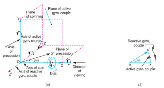
We have already discussed that the angular acceleration is the rate of change of angular velocity with respect to time. It is a vector quantity and may be represented by drawing a vector diagram with the help of right hand screw rule (see chapter 2, Art. 2.13)
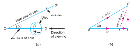
Consider a disc, as shown in Fig. 14.1 (a), revolving or spinning about the axis OX (known as axis of spin) in anticlockwise when seen from the front, with an angular velocity ω in a plane at right angles to the paper. After a short interval of time δt, let the disc be spinning about the new axis of spin OX ′ (at an angle δθ) with an angular velocity (ω + δω). Using the right hand screw rule, initial angular velocity of the disc (ω) is represented by vector ox; and the final angular velocity of the disc (ω + δω) is represented by vector ox′ as shown in Fig. 14.1 (b). The vector xx′ represents the change of angular velocity in time δti.e. the angular acceleration of the disc. This may be resolved into two components, one parallel to ox and the other perpendicular to ox. Component of angular acceleration in the direction of ox


Since δθ is very small, therefore substituting cos δθ=1, we have

In the limit, when 
Component of angular acceleration in the direction perpendicular to 

Since δθ in very small, therefore substituting sin δθ=δθ, we have
 (Neglecting
  being very small)
In the limit, when 

 Total angular acceleration of the disc


the plane in which the axis of spin is going to rotate. This angular velocity of the axis of spin (i.e. dθ/dt) is known as angular velocity of precession and is denoted by ωP . The axis, about which the axis of spin is to turn, is known as axis of precession. The angular motion of the axis of spin about the axis of precession is known as precessional angular motion
Gyroscopic Couple Consider a disc spinning with an angular velocity ω rad/s about the axis of spin OX, in anticlockwise direction when seen from the front, as shown in Fig. 14.2 (a). Since the plane in which the disc is rotating is parallel to the plane YOZ, therefore it is called plane of spinning. The plane XOZ is a horizontal plane and the axis of spin rotates in a plane parallel to the horizontal plane about an axis O Y. In other words, the axis of spin is said to be rotating or processing about an axis O Y. In other words, the axis of spin is said to be rotating or processing about an axis OY (which is perpendicular to both the axes OX and OZ) at an angular velocity ωP rap/s. This horizontal plane XOZ is called plane of precession and O Y is the axis of precession.
Let I = Mass moment of inertia of the disc about OX, and
ω = Angular velocity of the disc.
∴ Angular momentum of the disc = I.ω
Since the angular momentum is a vector quantity, therefore it may be represented by the vector ox → , as shown in Fig. 14.2 (b). The axis of spin OX is also rotating anticlockwise when seen from the top about the axis O Y. Let the axis OX is turned in the plane XOZ through a small angle δθ radians to the position OX ′, in time δt seconds. Assuming the angular velocity ω to be constant, the angular momentum will now be represented by vector ox′.
∴ Change in angular momentum


and rate of change of angular momentum

Since the rate of change of angular momentum will result by the application of a couple to the disc, therefore the couple applied to the disc causing precession,

where ωP = Angular velocity of precession of the axis of spin or the speed of rotation of the axis of spin about the axis of precession O Y. In S.I. units, the units of C is N-m when I is in kg-m2.
A Gyroscopic stabilizer is a control system that reduces tilting movement of a ship or aircraft. It senses orientation using a small gyroscope, and counteracts rotation by adjusting control surfaces or by applying force to a large gyroscope. It can be:
- Anti-rolling gyro, or ship stabilizing gyroscope, applies force to a large gyroscope.
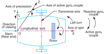
Steering is the turning of a complete ship in a curve towards left or right, while it moves forward. Consider the ship taking a left turn, and rotor rotates in the clockwise direction when viewed from the stern, as shown in Fig. 14.8. The effect of gyroscopic couple on a naval ship during steering taking left or right turn may be obtained
When the rotor of the ship rotates in the clockwise direction when viewed from the stern, it will have its angular momentum vector in the direction ox as shown in Fig. 14.9 (a). As the ship steers to the left, the active gyroscopic couple will change the angular momentum vector from ox to ox′. The vector xx′ now represents the active gyroscopic couple and is perpendicular to ox. Thus the plane of active gyroscopic couple is perpendicular to xx′ and its direction in the axis OZ for left hand turn is clockwise as shown in Fig. 14.8. The reactive gyroscopic couple of the same magnitude will act in the
opposite direction (i.e. in anticlockwise direction). The effect of this reactive gyroscopic couple is to raise the bow and lower the stern. Notes: 1. When the ship steers to the right under similar conditions as discussed above, the effect of the reactive gyroscopic couple, as shown in Fig. 14.9 (b), will be to raise the stern and lower the bow. 2. When the rotor rates in the anticlockwise direction, when viewed from the stern and the ship is steering to the left, then the effect of reactive gyroscopic couple will be to lower the bow and raise the stern. 3. When the ship is steering to the right under similar conditions as discussed in note 2 above, then the effect of reactive gyroscopic couple will be to raise the bow and lower the stern. 4. When the rotor rotates in the clockwise direction when viewed from the bow or fore end and the ship is steering to the left, then the effect of reactive gyroscopic couple will be to raise the stern and lower the bow. 5. When the ship is steering to the right under similar conditions as discussed in note 4 above, then the effect of reactive gyroscopic couple will be to raise the bow and lower the stern. 6. The effect of the reactive gyroscopic couple on a boat propelled by a turbine taking left or right turn is similar as discussed above.
Let m=mass of the vehicle in kg.
W= weight of the vehicle in Newton =m.g
 = radius of the wheels in metres.
R= radius of curvature in metres
h= distance of centre of gravity, vertically above the road surface in metres,
x= width of track in metres,
 = mass moment of inertia of one of the wheels in kg-m^3
 = Angular velocity of the wheels for velocity of spin in rad/s.
 = mass moment of inertia of the rotating parts of the engine
 = Angular velocity of the rotating parts of the the engine in rad/s.
G= gear ratio=
v= linear velocity of the vehicle in m/s =
Therefore
Road reaction over each wheel =W/4=m.g/4 Newton’s
Let us now consider the effect of the gyroscopic couple and centrifugal couple on the vehicle.
Since the vehicle takes a turn towards left due to the precession and other rotating parts, therefore a gyroscopic couple will act.
We know that velocity of precision,

Gyroscopic couple due to four wheels

And gyroscopic couple due to rotating parts of the engine,

Net gyroscopic couple,


P × x = C. Or. P=C/x
Vertical reaction at each of the outer or inner wheels,
P/2 =C/2x
This gyroscopic couple is balanced by vertical reactions, which are vertically upwards on the outer wheels & vertically downwards on the inner wheels.
2. Effect of the centrifugal couple

The couple tending to overturn the vehicle or overturning couple,

This overturning couple is balanced by vertical reactions, which are vertically upwards on the outer wheels & vertically downwards on the inner wheels.
Vertical reaction at each of the outer or inner wheels,

Vertical reaction at each of the outer or inner wheels,

Total vertical reaction at each of the outer wheel,

And total vertical reaction at each of the inner wheel,

Stability of a two wheeler vehicle taking a turn
Consider a two wheeler taking a right turn as shown in figure
Let m=mass of the vehicle and its rider in kg.
W=weight of the vehicle and its rider in Newton’s =m.g
h= height of the centre of gravity of the vehicle and rider.
 =radius of the wheels,
R= radius of track or curvature.
 =mass moment of inertia of each wheel,
 =mass moment of inertia of the rotating parts of the engine,
 = Angular velocity of the wheels,
 = Angular velocity of the engine,
G= gear ratio = 
v= linear velocity of the vehicle= 
 = Angle of heel. It is inclination of the vehicle to the vertical for equilibrium.
Let us now consider the effect of the gyroscopic couple and centrifugal couple on the vehicle, as discussed below.
We know that 


and velocity of precession 


Gyroscopic couple,


2. Effect of centrifugal couple
We know that centrifugal force,

This force acts horizontally through the centre of gravity along the outward direction,
Centrifugal couple,

Since the centrifugal couple has a tendency to overturn the vehicle, therefore total overturning couple,
 = Gyroscopic couple +centrifugal couple


We know that balancing couple =m.g.h.sin
The balancing couple acts in clockwise direction when seen from the front of the vehicle.
Therefore for stability, the overturning couple must be equal to the balancing couple, i.e.

From this expression, the value of the angle of heel may be determined, so that the vehicle does not skid.
Numericals
1. Find the angle of inclination with respect to the vertical of a two wheeler negotiating a turn. Given combined mass of the vehicle with its rider 250kg: moment of inertia of the engine flywheel 0.3kg . Moment of inertia of each road wheel
  speed of engine flywheel 5 times that of road wheels and in the same direction; height of centre of gravity of rider with vehicle 0.6m. two wheeler speed 90 km/h; wheel radius 300 mm; radius of turn 50m.
Solution Given m=250Kg , h=0.6m . v=90km/h = 25m/s, R=50m

Let  =Angle of inclination with respect to the vertical of a two wheeler
We know that gyroscopic couple,


And centrifugal couple 
Total overturning couple,

We know that balancing couple,

Since the overturning couple must be equal to the balancing couple for equilibrium condition therefore


2. A ship propelled by a turbine rotor which has a mass of 5 tonnes and a speed of 2100 rpm. The rotor has a radius of gyration of 0.5 metre and rotates in clockwise direction when viewed from the stern. Find the gyroscopic effects in the following conditions:
Determine also the maximum angular acceleration during pitching. Explain how the direction of motion due to gyroscopic effect is determined in each case.
Solution Given m=5 t=5000kg N=2100r.p.m or  k=0.5m
1. When the ship steers to the left
Given: v=30km/h =8.33m/s : R=60m
We know that angular velocity of precession

And mass moment of inertia of the rotor

Gyroscopic couple,

When the rotor in a clockwise direction when viewed from the stern and the ship steers to the left, the effect of reactive gyroscopic couple is to raise the bow and lower the stern.
2. When the ship pitches with the bow descending
Given:
We know that angular velocity of simple harmonic motion

And maximum angular velocity of precession

Maximum gyroscopic couple

Since the ship is pitching with the bow descending therefore the effect of this maximum gyroscopic couple is to turn the ship towards port side.
3.When the ship rolls
Since the ship rolls at an angular velocity of 0.03rad/s therefore angular velocity of precession when the ship rolls,

Gyroscopic couple

In case of rolling of a ship the axis of precession is always parallel to the axis of spin for all positions, therefore there is no effect of gyroscopic couple.
Maximum angular acceleration during pitching
We know that maximum angular acceleration during pitching.

3. A four wheeled motor car of mass 2000 kg has a wheelbase 2.5 m, track with 1.5 m and height of centre of gravity 500 mm above the ground level and lies at 1 metre from the front Excel. Each wheel has an effective diameter of 0.8m and a moment of inertia of 0.8 kg- the drive shaft, engine flywheel and transmission are rotating at four times the speed of road wheel, in a clockwise direction when viewed from the front, and is equivalent to a mass of 75kg having a radius of gyration of 100mm. If the car is taking a right turn of 60m radius at 60km/h. Find the load on each wheel.
Solution Given m=2000kg: b=2.5m: x=1.5m: h=500mm = 0.5m: L=1m: R=60m: v=60km/h =16.67m/s

Since the centre of gravity of car lies at 1 m from the front axle and the weight of the car lies at the centre of gravity, therefore weight on the front wheels and rear wheels will be different.
Let  Weight of the front wheels,and
 =Weight on the rear wheels,
Taking moment about the front wheels,


We know that weight of the car or on the four wheels,


Weight on each of the front wheels

And weight on each of the rear wheels

Since the weight of the car over the four wheels will act downwards, therefore the reaction between each wheel and the road surface of the same magnitude will act upwards as shown in Fig.
Let us now consider the effect of gyroscopic couple due to four wheels and rotating parts of the engine.
We know angular velocity of wheels

And angular velocity of precession

Gyroscopic couple due to four wheels


This gyroscopic couple tends to lift the inner wheels and to press the outer wheels. In other words, the reaction will be vertically downward on the inner wheels and vertically upward on the outer wheels as shown in fig.
Let P/2 newtons be the magnitude of this reaction at each of the inner or outer wheel.

We know that mass moment of inertia of rotating parts of the engine,

Gyroscopic couple due to rotating parts of engine


This gyroscopic couple tends to lift the front wheels and to press the outer wheels. In other words, the reaction will be vertically downwards on the front wheels and vertically upwards on the rear wheels as shown in Fig.
Let F/2 newtons be the magnitude of this reaction on each of the front and rear wheels

Now let us consider the effect of centrifugal couple acting on the car. We know that centrifugal force,

Centrifugal couple tending to overturn the car or over turning couple,

This overturning couple tends to reduce the pressure on the inner wheels and to increase on the outer wheels. In other words, the reactions are vertically downward on the inner wheels and vertically upwards on the outer wheels.Let Q/2 be the magnitude of this reaction on each of the inner and outer wheels.

From figure we see that
Load on the front wheel 1

Load on the front wheel 2

Load on the front wheel 3

Load on the rear wheel 4

4. A rear engine automobile is travelling along a track of 100 meters mean radius. Each of the four road wheels has a moment of inertia of 2.5 and an effective diameter of 0.6m. The rotating parts of the engine have a moment of inertia of
  . The engine axis is parallel to the rear axle and the crankshaft rotates in the same sense as the road wheels. The ratio of engine speed to back axle speed is 3:1 .The automobile has a mass of 1600kg and has its centre of gravity 0.5m above road level. The width of the track of the vehicle is 1.5m
Determine the limiting speed of the vehicle around the curve for all four wheels to maintain contact with the road surface. Assume that the road surface is not cambered and centre of gravity of automobile lies centrally with respect to the four wheels.
Solution Given R=100m: m=1600kg: h=0.5m:x=1.5m

The weight of the vehicle will be equally distributed over the four wheels which will act downwards. The reaction between the wheel and the road surface of the same magnitude will act upwards.
Road reaction over each wheel
=W/4=m.g/4=1600*9.81/4=3924N
Let v=Limiting speed of the vehicle in m/s
We know that angular velocity of the wheels

And angular velocity of precession

Gyroscopic couple due to 4 wheels

And gyroscopic couple due to rotating parts of engine


Total gyroscopic couple

Due to this gyroscopic couple the vertical reaction on the rails will be produced. The reaction will be vertically upwards on the outer wheels and vertically downwards on the inner wheels. Let the magnitude of this reaction at each of the outer or inner wheel be P/2newtons.

We know that centrifugal force

Overturning couple acting in the outward direction

This overturning couple is balanced by vertical reactions which are vertically upwards on the outer wheels and vertically downwards on the inner wheels Let the magnitude of this reaction at each of the outer or inner wheels be Q/2 newtons.

We know that total vertical reaction at each of the outer wheels

And total vertical reaction at each of the inner wheels

From equation (i) we see that there will always be contact between the outer wheels and the road surface because W/4 P/2 and Q/2 are vertically upwards, In order to have contact between the inner wheels and road surface the reactions should also be vertically upwards which is only possible if


References:
1. Ghosh Malik, Theory of Mechanism and Machines, East-West Pvt. Ltd.
2. Hannah and Stephans, Mechanics of Machines, Edward Arnolde Publication.
3. R L Norton, Kinematics and Dynamics of Machinery, First Edition, McGraw Hill Education(India) P Ltd. New Delhi
4. Sadhu Singh, Theory of Machines, Pearson
5. D.K. Pal, S.K. Basu, Design of Machine Tools, Oxford &Ibh Publishing Co Pvt. Ltd.
6. Dr. V. P. Singh, Theory of Machine, Dhanpatrai, and sons.
7. C. S. Sharma & Kamlesh Purohit, “Theory of Machine and Mechanism”, PHI.
8. Mr. C. Ravindran, Department of Mechanical Engineering S.C.E, Vijayamangalam.