Unit 1
Fundamentals of Electrical Circuits
It is equal to the terminal potential difference when no current flows. Its unit is volts. EMF is the amount of energy (E) provided by the battery to each coulomb of charge (Q) passing through. One terminal of the device becomes positively charged, the other becomes negatively charged. The work done on a unit of electric charge, or the energy thereby gained per unit electric charge, is the electromotive force. Electromotive force is the characteristic of any energy source capable of driving electric charge around a circuit.
Ideal and practical Voltage and Current source:
A voltage source is a device which provides a constant voltage to load at any instance of time and is independent of the current drawn from it. This type of source is known as an ideal voltage source. Practically, the ideal voltage source cannot be made. It has zero internal resistance. It is denoted by this symbol.
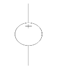
Fig: Voltage source symbol
Ideal Voltage Source
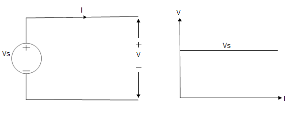
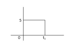
Fig: Ideal Voltage Source
The graph represents the change in voltage of the voltage source with respect to time. It is constant at any instance of time.
Voltage sources that have some amount of internal resistance are known as a practical voltage source. Due to this internal resistance, voltage drop takes place. If the internal resistance is high, less voltage will be provided to load and if the internal resistance is less, the voltage source will be closer to an ideal voltage source. A practical voltage source is thus denoted by a resistance in series which represents the internal resistance of source.
Practical Voltage source
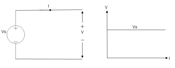
Fig: Practical Voltage source
The graph represents the voltage of the voltage source with respect to time. It is not constant but it keeps on decreasing as the time passes.
Current source
A current source is a device which provides the constant current to load at any time and is independent of the voltage supplied to the circuit. This type of current is known as an ideal current source; practically ideal current source is also not available. It has infinite resistance. It is denoted by this symbol.
Ideal Current source
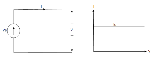
Fig: Ideal Current source
The graph represents the change in current of the current source with respect to time. It is constant at any instance of time.
Why ideal Current source has infinite resistance?
A current source is used to power a load, so that load will turn on. We try to supply 100% of the power to load. For that, we connect some resistance to transfer 100% of power to load because the current always takes the path of least resistance. So, in order for current to go to the path of least resistance, we must connect resistance higher than load. This is why we have the ideal current source to have infinite internal resistance. This infinite resistance will not affect voltage sources in the circuit.
Practical Current source
Practically current sources do not have infinite resistance across there but they have a finite internal resistance. So the current delivered by the practical current source is not constant and it is also dependent somewhat on the voltage across it.
A practical current source is represented as an ideal current source connected with resistance in parallel.
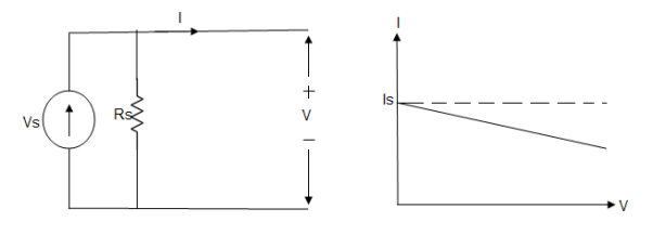
Fig; Practical Current source
The graph represents the current of the current source with respect to time. It is not constant but it also keeps on decreasing as the time passes.
Examples of current and voltage sources
The examples of current source are solar cells, transistors and examples of some voltage sources are batteries and alternators.
This was all about ideal and practical sources of power. The ideal sources are very useful for calculations in theory but as ideal sources are not practically possible, only practical sources are used in practical circuits. The batteries we use are a practical source of power and the voltage and current decreases as we use it. Thus both are useful to us in their own ways.
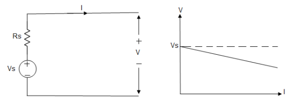
- From VI:
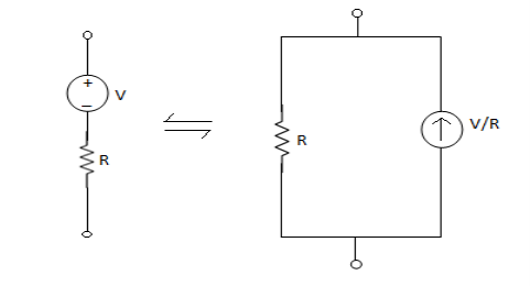
2. From IV:
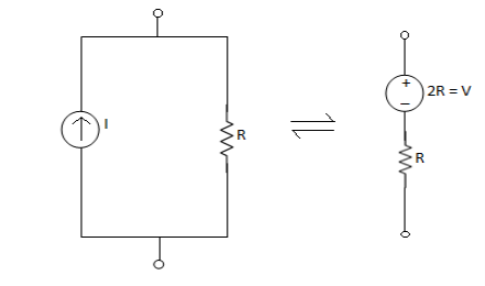
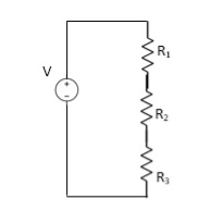
VDF - Voltage Division Formula


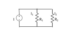
CDF - Current Division Formula


- Resistor: -


Resistance is affected by temperature
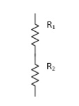

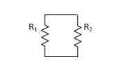


Behavior of Resistance:-


R R R R
Capacitor: charge storing device (voltage)


When the potential is applied to the capacitor one plate of positive potential and other is negative. It stores energy in the form of potential drop. This is called charging of capacitor. When the capacitor gives its stored energy in the circuit is called as discharging.

Electrostatic Energy

Capacitor does not respond any change as far as voltage is concerned.
Definition of Open circuit and short circuit
 s
s


Short Circuit:
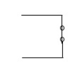


 may or may not be zero
Time Constant
The series RC circuit is shown below.
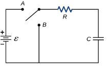
Fig: Series RC circuit
 =V
=V
For t>0 applying KVL
Ri(t)+ +V=0
+V=0

Hence general solution of above equation is calculated same as for RL circuit
i=k
i(0)=- 
Hence, particular solution for network is given as
i=-  for tfor t≥0
= for t<0
The time constant is given as 
 =RC
=RC
It converts chemical energy into electric energy. A combination of two or more voltaic cells is called as battery. Due to chemical reaction inside the cell voltage is produced. Electrodes are immersed in an electrolyte, which forces the electric charge to separate in the form of ions and free electrons.
i) Primary Batteries:
These are basically disposable batteries. They can be used only once. They are not rechargeable. EX. AA, AAA.
Types of Primary Batteries:
(a) Carbon- zinc dry cell: These are AA, AAA. They have zinc electrode as negative electrode and carbon as positive electrode. The output voltage of a single cell is about 1.5 V.
(b) Alkaline cell: It is AA type. It lasts long than carbon-zinc cell. It consists of a zinc anode and manganese dioxide cathode in an alkaline electrolyte
(c) Zinc chloride cell: These are heavy duty cells. It is modified zinc-carbon cell.
(d) Mercury cell: It is not used these days. It consists of zinc anode, mercury compound cathode and potassium or sodium hydroxide electrolyte.
(e) Silver oxide cell: This cell consists of a zinc anode, silver oxide cathode, and potassium of sodium hydroxide electrolyte. Normally used in cameras and watches.
(f) Lithium cell: It is light weight. It offers high output voltage. Two forms of 3V output in widespread use: (a) Lithium-sulfur dioxide(LiSO2 ). (b) Lithium- thionyl chloride.
Ii) Secondary Batteries:
These are rechargeable batteries. These are also called as storage batteries. They are rechargeable because the electric current reverses the chemical reaction inside the batteries that occurred during use. EX used in mobile phones, MP3 players.
Types of Secondary Cells:
(a) Lead-acid cell: It is most commonly used cell. It has porous lead anode and lead-oxide cathode. Used in automobile inverters. The output is of 2.1V.
(b) Nickel cadmium (NiCd) cell: It has Nickel hydroxide anode and cadmium hydroxide cathode. It delivers high current. It is used in cadmium hydroxide electrolyte. Used in alarm systems, TV equipment.
(c) Lithium-ion battery: It has graphite anode and lithium manganese dioxide cathode. The electrolyte used is mixture of lithium salts.
(d) Nickel-metal- hydride (NiMH) cell: They are used in power tools. They only have negative electrode, rest all similar to NiCd cells.
(e) Nickel-iron (Edison) cell: They have Nickel hydroxide anode and iron cathode with potassium hydroxide electrolyte. They are not in use now.
(f) Fuel cell: It converts chemical energy into water and produces electricity. They are used as source of DC power in space program. They are very efficient.
(g) Solar cell: They convert sunlight to electric energy. They are arranged in modules to form an array called solar array. An applied voltage higher than the voltage of one cell can be obtained by connecting cells in series. The total voltage available across the battery of cells is equal to the sum of the individual values for each cell. Parallel cells have the same voltage as one current capacity
Reference’s
1.Theory and Problems of Basic electrical Engineering : Nagrath Kothri
2.Electrical technology by B.L.Theraja, A.K.Theraja: S chand publication
3.Basic Electrical Engineering : V K Mehta
4.Basic Electrical Engineering : S K Sahdev: Pearson publication
5.Electrical Safety, Fire Safety engineering S.Rao, Khanna Publication