Unit 2
DC Circuits
The characteristics of the circuit elements the electrical network can be classified as
i) Linear Network: The ohm’s law is applicable in these types of networks. They consist of elements such as R, L and C which are always constant with respect to change in time voltage temperature etc. They follow law of superposition.
Ii) Non-Linear Network: These networks do not follow superposition theorem and the circuit parameters changes with time voltage temperature etc.
Iii) Bilateral Network: The circuit whose characteristics are same irrespective to the direction of current flow in the circuit.
Iv) Unilateral Network: The circuits whose operation depends on the direction of current flow through various elements in the circuit. Ex diode.
v) Active Network: The elements which deliver power or energy are called as Active elements. For example: Transistor, Voltage and Current source.
Vi) Passive Network: The elements which absorb power are called as passive elements. For example: Resistor, Inductor and capacitor.
Vii) Lumped Network: A network in which all the network elements are physically separable is known as lumped network.
Viii) Distributed Network: The network in which elements like resistance, inductance cannot be separated physically for analysing the circuit.
Statement: the algebraic summation of all Voltage in any closed circuit or mesh of loop zero.
Ie ∑ Voltage in closed loop = 0 the summation of the Voltage rise (voltage sources) is equal to summation of the voltage drops around a closed loop in 0 circuit for explanation from here
Determination of sigh and direction of currents (Don’t write in exams just for understanding)

Current entering a resistor is +ve and leaving should be –ve
Now
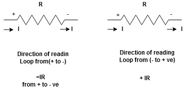


Potential Rise Potential Drop
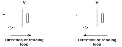
We are reading from +V to –V we are reading from –V to +V
 potential drops
  potential rise
 -V
-V  +V
+V
Given Circuit
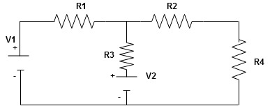
First identify no of loops and assign direction of current flowing in loop
Note : no of loops in circuit = No, of unknown currents = no, of equations in the circuit
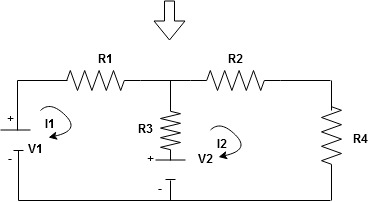
Note : keep loop direction and current direction same ie either clockwise or anticlockwise for all loops I1 I2
Now according to direction of direction assign signs (+ve to –ve) to the resistors
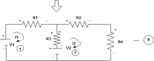
Note : voltage sources (V) polarities does not change is constant.
Note: for common resistor between 2 loops appearing in the circuit like R3 give signs according to separate loops as shown
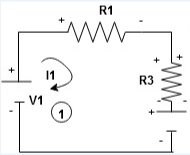
When considering only loop no 1 (+ R3 - )
- B
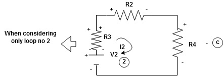
Now consider diagram A and write equations
Two loops  two unknown currents
  two equation
Apply KVL for loop ① [B. Diagram ]
(+ to drop -) = - sign and (- to rise +) = + sign
 for drop = -sign
 for rise = + sign
-
-( ) R2 is considered because in R3,2 currents are flowing
  and
and  and we have taken (
 ) because we are considering loop no 1 and current flowing is
  in loop no 1
 )
)
Similarly for loop no. 2 currents flowing is  resistor R3 it should be
  )R3
)R3
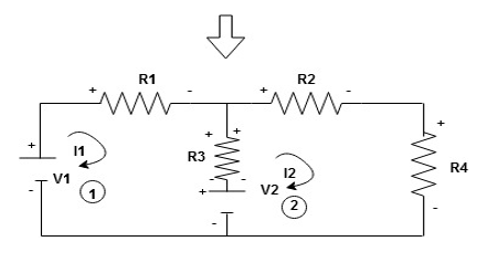
Consider loop no. 1 apply KVL
- …….①
…….①
-
Consider loop no. 2 apply KVL
- …….②
…….②
-
After solving equation ① and ② we will get branch current  and
and 
LOOP ANALYSIS
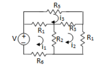
For Loop 1 with il

For Loop 2 with i2

For Loop 3 with i3

Example 1. For the circuits given below write the voltage equations:
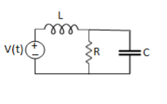
Solution: Let current i1be in loop 1 current and i2 for loop 2
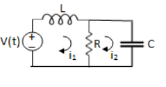


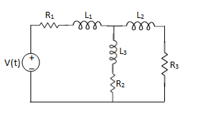
Solution:
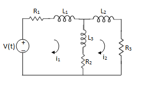
For loop 1

For loop 2

NODE ANALYSIS
For these we assume every node as a voltage point and write the current equation for every element. For current source, current entering is negative.
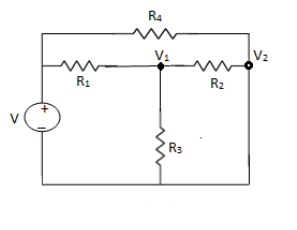
For node V1

For node V2

For V

Example: Using nodal analysis find voltage across 5resistor.
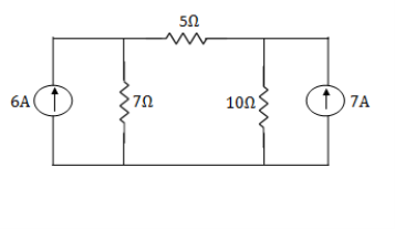
Solution:
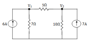
For V1


 1
1
For V2


 2
2
Solving 1 and 2:


For 5 voltage = 
= -50.9 + 57.27
= 6.37V
- This is only applicable to circuits with linear elements.
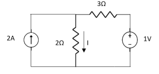
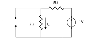
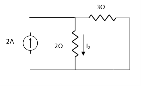
- If two or more than two independent sources (voltage or current) are operating in the circuit than voltage across any element or current through any element is sum of current and voltages due to individual sources.
Question 1. Find the current through  resistance.
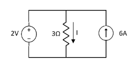
Solution:
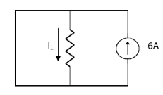
 1= 0
1= 0
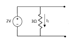
 2=
2=
 1 +
1 +  2
2 
Special Case:
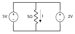
Since two voltage sources with different magnitude in parallel which cannot be connected as in single branch two different current is not possible (if 5V than I = zero).
Question:
 1 =
1 = 
 2 =
2 = 
=
 1 +
1 +  2
2
= 

Thevenin’s equivalent of A
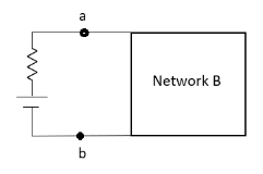
Norton’s equivalent of A
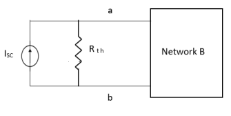
 sc = Vth/Rth
- Norton’s equivalent is obtained by source conversion of thevenin’s equivalent circuit.
CONDITIONS FOR APPLICATION
- For network A:
- Network A should contain linear elements.
- Network A can have independent and dependent current and voltage source.
- If network A has dependent source than controlling parameter must lie in network A itself.
- Network A should not have any source coupling and magnetic coupling.
- For network B:
- It can have linear and non linear elements.
- It can have dependent and independent voltage and current sources.
- It should not have any source and magnetic coupling with network A.
Method for finding Rth :
Firstly, open circuit terminal A and B.
- If network is operating with only independent sources:
- Make all sources zero in network A.
- Find out the equivalent resistance across terminal A and B.
2. If network A is operating with independent and dependent sources:
- Make all independent sources zero in network A.
- Connect a generation between A and B.
3. If network is operating with only dependent sources:
Connect generation between A and B

Method for Vth:
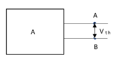
First open circuit terminal A and B.
Find out the voltage between A and B this is Vth
Method for Isc:
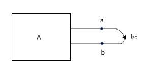
- Isc =

- Remove network B and S.C. The terminal A and B and current from terminal A to B Isc.
Question:
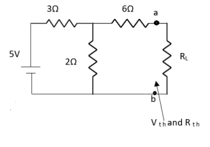
Answer:
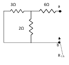


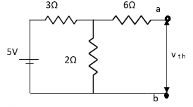


Finding Isc from circuit directly:
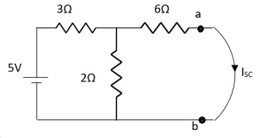
By KCL,


Question:
Answer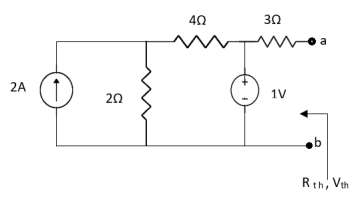
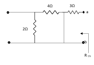
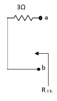
Also, clear from circuit that Vth = 1V.
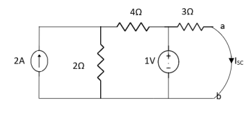
By applying KVL we get,
1-3Isc=0
Isc= A
A
Que:
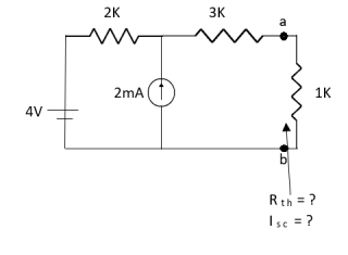
Ans;
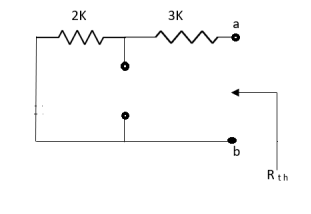
Rth=3k+2k=5k
By applying KVL we get


Therefore, 
Question:
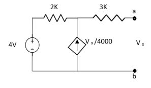
Solution: For Rth
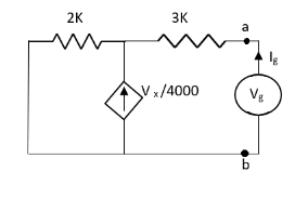
By KCL,


But, 


By KVL,


Question:
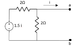
Solution: Since, no independent source is present so,
Isc = 0
And we know that,


Since Rth cannot be zero
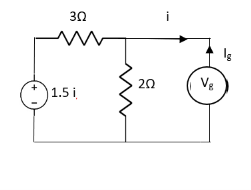


But 


Question: Find out the Norton’s equivalent
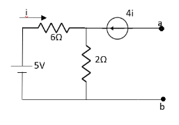
Solution:
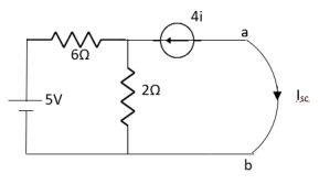
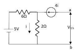

Since, there is no significance of current source


 A
A
Star-Delta
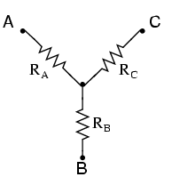
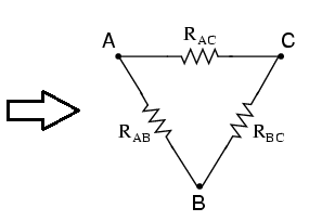
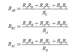
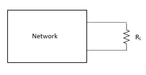

Where Rth is Thevenin’s equivalent resistance across a and b.
Maximum power is absorbed by ZL when
Condition: 


Comparing real and imaginary parts


OR


Maximum power absorbed by ZL is


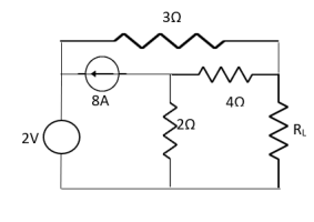
Question: Find out the value of load resistance if power absorbed is maximum.
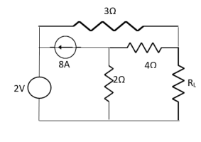
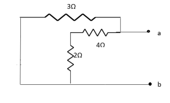
Solution: find Thevenin’s equation

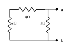


Question: Find maximum power delivered is RL if its value is
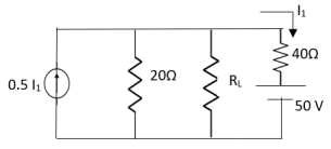
- 16Ω
 Ω
Ω- 60Ω
- 20Ω
Solution
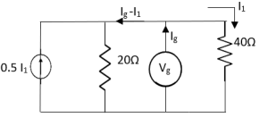


Therefore, 
Reference’s
1.Theory and Problems of Basic electrical Engineering :NagrathKothri
2.Electrical technology by B.L.Theraja, A.K.Theraja: S chand publication
3.Basic Electrical Engineering : V K Mehta
4.Basic Electrical Engineering : S K Sahdev: Pearson publication
5.Electrical Safety, Fire Safety engineering S.Rao, Khanna Publication