Unit 6
Electrical Utilities
House-wiring
There are five types of electrical house wiring systems listed below
i) Cleat Wiring: The wires used are PVC insulated and they are braided and compounded on walls or ceiling with porcelain cleats. Now a days this system is not used. They are used in army campuses.
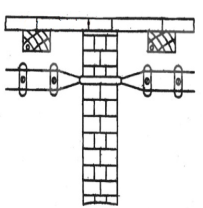
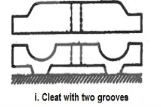
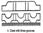
There are some advantages of this type of wiring. They are Cheap and easy wiring. It has Easy to fault detection. They are easy to repair.
Ii) Casing Wiring: They are VIR or PVC insulated. They are carried through wooden enclosures. They are obsolete now. The casing was made of strip of wood with parallel grooves cut lengthwise. It is strong and long-lasting wiring system.The wiring can be easily done in this wiring system.If Phase and Neutral wire is installed in separate slots, then repairing is easy.Stay for long time in the field due to strong insulation of capping and casing.
Iii) Batten Wiring: A group of cables are laid n straight teak wooden batten. The brass links are used to hold the wires. The brass pins are used to fix these links which are placed after each 10cm horizontal and 15cm vertical run.
Iv) Conduit Wiring: On the surface of the wall or ceiling conduit pipes (with GI wire inside) are attached with help of 2-hole strap and base clip at a regular certain distance. They are difficult to install. They are safest in all types of wirings used. There is no risk of fire and damage of cable insulation. On the basis of metallic conduit there are two class one is class A conduit in which thin layer steel sheet low gauge conduit is used and class B in which thick sheet of steel high gauge conduit is used. A solid PVC conduit is used as non-metallic conduit.
v) Concealed Wiring: These are under the plaster of wall. The conduit pipes are under the plaster of wall with GI wires inside them. The PVC main cables are drawn through conduit with help of GI wires.
Godown-wiring
These wirings are used to operate lamps in the godowns. The circuit is shown below with lamps. The arrangements are made such that when one light is turned on the other automatically gets switched off.
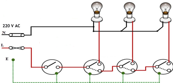
The common pole of first switch is connected to phase. The first throw of switch is connected to load and other to the common pole of next switch. In unused state the common poles of all switches are at first throw of switch.In such an arrangement, changing the switch position to 2nd throw OFF’s previous load and ON the next one. There can be any number of loads depending on the requirements. The power consumption is not affected as only one lamp is on at any instance. The length of wire only increases with the number of loads.
Staircase Wiring
The staircase wiring done with 2-way switch is explained below. These switches are called SPDT i.e. single pole double throw switches. This helps us to use same wiring from different places.
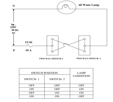
The above shown is the circuit for 2-way switch. One switch is installed near first step and second switch at the upper end of stair. The supply is given to the switch at the short-circuited terminals. The connection to the light point is taken from the similar short-circuited terminal of the second switch , other two independent terminals of each circuit are connected through cables.
It means connecting electrical equipment to earth with very low resistance wire. This ensures safe discharge of electrical energy due to failure of the insulation line coming in contact with the casing, etc. Earthing brings the potential of the body of the equipment to zero.
The main purpose of Earthing is to protect the operating personnel from shock. Under unbalanced load maintain the line voltage. To avoid risk of fire due to leakage currents. For protecting the equipment.
Methods of Earthing:
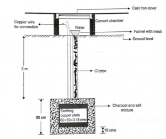
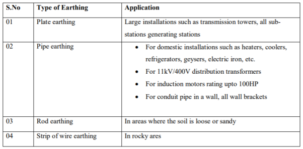
(i) Plate earthing: A copper plate of dimension 60cm x 60cm x 3.18 is used for earthing. The plate is buried in ground and layered with coal and salt. Then water is poured to maintain the earth’s electrode resistance below maximum value. The earth wire is bolted to the earth plate.
(ii) Pipe earthing:
The earth’s electrode made of galvanized iron pipe with holes on surface is placed upright in wet ground. In order to maintain the earth’s resistance, the pipe is filled with mixture of salt and coal. 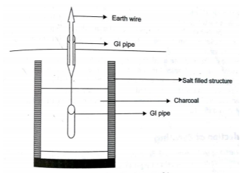
This system can carry larger leakage currents compared to plate earthing method.
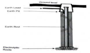
(iii) Rod earthing: It is similar to pipe earthing method. A copper rod is buried upright in the earth manually or with pneumatic hammer. The length of embedded electrodes in soil reduces earth resistance to a desired level.
(iv) Strip or wire earthing: In this the earthing strip electrodes are buried in horizontal trenches of depth 0.5m. The copper plate or round conductors are used. The length of the conductor buried in the ground would give a sufficient earth resistance and this length should not be less than 15m. The electrodes shall be as widely distributed as possible in a single straight or circular trench radiating from a point. This type of earthing is used where the earth bed has a rocky soil and excavation work is difficult.
Application
The primary measures required to keep ourself and the equipment Safe are listed below
i) The hands or the equipment to be repaired or checked should not have any trace of water on it.
Ii) The equipment should not be of damaged insulation or broken chords.
Iii) The equipment before installation should be tested first.
Iv) The instruments should be identified and checked properly before fitting.
v) The site of work should have a board to notify that work is in progress.
Vi) The site where work is going on installation or any repair should be done after the site is earthed properly.
Vii) During heavy lighting and storm avoid working with electrical equipment.
Viii) The tools used while working should not be tossed it should be delivery by hand to the other person.
Ix) The shoes with rubber soles should be worn during work.
x) Insulated tools should be used.
Xi) If we have to repair anything at home always turn off the mains first.
Xii) Proper insulated rubber gloves and googles should be used.
Xiii) Always a wooden ladder should be used, avoid using steel ladders during work.
Xiv) Remember wire code of the country.
Xv) Never repair energised equipment, take and tester check first than use.
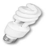
CFL (Compact Fluorescent Lamp): They are the smaller version of common fluorescent lights which are used. The old CFLs had delay or flicker when turned on because they used magnetic ballasts. The new CFLs use magnetic ballasts. The CFLs life equivalent to 10 incandescent lamps.
Construction
The traditional fluorescent lamp tube is only used here. This tube is bent into compact size such that it gets fixed in ordinary incandescent fixtures.
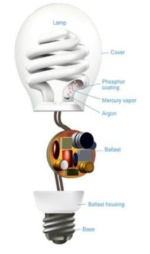
It consists of a soda lime glass tube which is filled with argon and a drop of mercury. The tube end is sealed with metal electrodes, they conduct electricity from the external circuit to the gas inside tube. The main parts of CFL are gas filled tube and the electronic blast. An electrical current from the ballast flows through the mercury vapor,emitting ultraviolet light.This, ultraviolet light further excites a phosphor coating present inside the tube.The coating is responsible for emitting visible light. They require more energy when they are turned on. It takes 30 seconds to 3minutes for the electricity to pass through the bulb and get it started. It happens so because the lamp also requires a current to preheat the filaments, a high voltage for ignition and finally a high frequency AC current for running. The electronic blast first converts AC to DC at low frequency in input and again converting DC to AC at the output on high frequency.
Advantages
- CFLs are cost efficient.
- CFLs are energy efficient, since it requires less energy to provide same amount of light.
- CFL light bulbs are long lasting and can last up to 10,000 hours.
- CFLs are very versatile and can fit into a standard light socket and do not call for any special lighting fixture.
- Dimmers are also available for some CFLs so as to control their brightness.
- CFLs comes in different colours and various shapes.
- Each CFL over its lifetime saves 450 pounds of carbon from being produced, considered to be a powerful saving.
LED
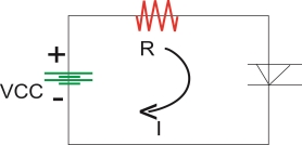
An LED emits light when electrical energy is applied to it. For proper operation it is necessary to forward bias the LED.
Construction of LED :-
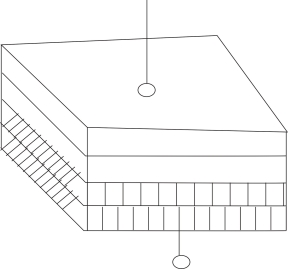
To make emission of light in one direction cup type construction is used for LED.
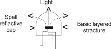
PRINCIPLE LED OPERATION
When the led is forward is forward biased the electrons in the n-region will cross the junction and recombine with the holes in the p- type material.
These free e- reside in the conduction band & hence at a higher energy level than the holes in the valence band
When recombination takes place this e- return peak to the valence band which is at a lower energy level than the conduction band.
While returning back the recombining e-give away the excess energy in the form of light . This process is called as electroluminescence in this way an LED emits light.
Color of the Emitted Light
Material Use Color of Emitted Light
i)Gallium Arsenide (GOAS) In fared (IR)
Ii) GaASP (gallium arsenide Red or Yellow
Phosphide)
Iii) Gallium phosphide (GAP) Red or Green
Application
Used in 7 Segment Display
Rating
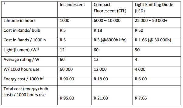
It is special type of arc discharge lamp invented by Dr.Reiling 1969 It works on the arc steam using iodide salt with argon gas and mercury vapour pressure at arc temperature of 1000K.
Construction and Working: The metal halide lamp consist of glass tube, arc tube, electrodes, glass stem, mercury vapour, argon gas and Indium thallium and sodium iodides as shown below.
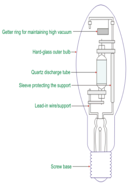
At the time of switching no arc is produced. The discharge between the main electrode and the auxiliary electrode is created by the glass stem. The bimetal switches short the starter electrode to the main electrode at the time of starting. An arc is created between the main and auxiliary electrode by the starter electrode that heats up the metal halide salts. When the arc temperature increases the metal iodides vaporize and diffuse from the wall into the arc stream. The argon gas and mercury get vaporise from arc than thallium gets vapourised and it forms a blue sheath around the thallium. At last sodium iodide gets vapourised and makes the lamp very sensitive to changesin the lamp wattage.
Ratings

Electronic Choke
It is an inductor used to block higher frequency when it allows dc to pass and will block lower frequency of ac in an electrical circuit. It is coil of insulated wire wound around a magnetic core.
There are two types of chokes:
i) Audio Frequency chokes: These are designed to block audio and power line frequency and allowing only dc to pass. They are having ferromagnetic cores which increase their inductance. They are similar to laminated core transformers. They are used in radio receivers. Some smaller chokes are used in switching power supplies to remove higher frequency switching transients from output.
Ii) Radio Frequency Choke: They are having iron powder or ferrite cores to increase the inductance. They reduce self-capacitance and losses as they are wound in complex pattern. They are seen on computer cables.
Iii) Common Mode Choke:In these type two coils are wound on single core. They reduce electromagnetic interference and radio frequency interference from power supply. They pass differential current and block common mode current.
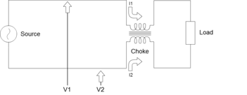
As windings are negatively coupled the magnetic flux produced by differential mode current in core cancel each other. Due to combined inductance of positive coupled windings the common mode currents have a high impedance. These chokes are used in industries, electrical and telecommunications applications for removing noise and electromagnetic interferences.
It is an electronic device used to measure voltage, current and resistance. It can also function as ohmmeter, voltmeter and ammeter. It has a needle over a numeric display for indication of the readings. It can be used to test continuity between two points in the circuit. The multimeter can be analog, digital and fluke multimeter.
Digital Multimeter:
- A Multi meter the most common measuring instrument. The name comes from multiple meters. There are two common types of Multi meter.
- The multimeter (DMMs) are the most commonMeasurement readings are displayed as numerical values on the LCD display. The display also alerts you to any pertinent symbols and warning.
- Digital meters on the other hand offer high accuracy have a high i/p impedance and are smaller in site.
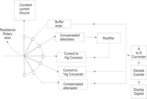
An instrument which is capable of measuring a.c. And d.c voltages a.c and d.c. current and resistances over several range is called digital multimeter. The various measurement possible by DMM are resistance a.c voltage and current d.c voltage and current. The selection of the parameter is possible with the help of rotary switch connected to i/p probes of DMM.
- Resistance Measurement : The rotary switch is in position 1 and resistance is connected to input probes. The constant current source Drives a current through unknown resistance. This produces Vtg across resistance which is directly proportional to the resistance. It is given to the buffer amplify and then to analog to digital converter. The ADC converts it to equivalent digital signal and it is displayed with the help of digital display a.c voltage measurement : The rotary switch is in position 2 and i/p a.cvtg is applied to probes if it is above the selected range it is attenuated with the help of compensated attenuator It is rectified to produce proportional d.cvtg then it is given to ADC which display it in volts
- A.c current measurement : the rotary switch is in position 3 and unknown current is applied across i/p probes it is converted to proportional vtg using current to vtg convertors
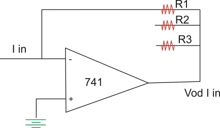
This I V converter is op-amp circuit as shown above. The op-amp/p current is zero hence I in flows through R1 and drop across R1osVo hence vtg o/p  the resistance R1 R2 and R3 are used for the proper range selection. This vtg is rectified and then given to ADC which displays the current in amperes.
3. D.c current measurement : The rotary switch is in position 4 and unknown d.c current is applied across i/p probes this vtg is given to ADC without rectification as this is proportional to d.c current ADC display it in amperes on digital display.
4. D.C voltage measurement : The rotary switch is in position 5 and unknown vtg is applied across i/p probes it is attenuated and directly given to ADC display it in volts.
Specifications of Digital Multimeter :
- D.C Voltage : this includes various d.c vtg ranges available along with the resolution and accuracy
- A.c Voltage : this includes various a.c vtg ranges available along with the resolution and accuracy.
- A.C current : this includes various a.c current ranges available along with the resolution and accuracy.
- Resistance : this includes the available resistance range typical six range are available from 200Ω to 20 MΩ the accuracy is
 0.1% of reading + two digits + 0.002Ω on the lowest range.
 - Input Impedance : The i/p Impedance is about 10 MΩ on all the range
- Normal mode noise rejection : this indicates the ability of the meter
It is greater than 60 dB at 50 HZ while the common mode noise rejection is greater than 90 dB at 50 HZ and greater than 120 dB at d.c
7. Overload protection: The overload protection of 1000 V d.c and 75 0ɤ.m.s. a.c is provided.
8. Diode test: The vtg drop across the diode can be measured for which 1 mA + 10% of constant current source is used.
9. Conductance: It can display Conductance in siemens
10. Relative Reference: when RF1 button is pressed the displayed reading is stored as a reference and then subtracted from the subsequent readings to indicate only amount of deviation from the reference.
11. Frequency: The frequency ranges is 200HZ to 200 kHZ auto selection.
Source of electrical power generation- Conventional-Hydro, Thermal, Nuclear and Diesel power station
The power system has mainly three stages i.e. its generation, transmission and distribution. The ways to generate power is discussed here. In over day to day life we require electricity, it has become a major system evolving in todays era with advancement in technology. As there is advancement in electronic technology, we need electricity for all those equipment’s and appliances to run. This electrical energy can be generated from various natural sources. These sources are renewable and non-renewable sources. In present system most of the energy is produced from non-renewable systems like coal, oil and natural gas. These non-renewable sources need to limit and hence energy from renewable sources are generated. The renewable sources are solar, wind, water, tidal and biomass. Below discussed plants use conventional energy sources like nuclear, hydro and thermal.
Hydro power plants:
In these stations water is used to run the turbine which is coupled to the generator. The water head needed for running the generator may be available naturally in some areas or they can also be created artificially in form of dams. These plants are eco-friendly because no fuel is required to run them.
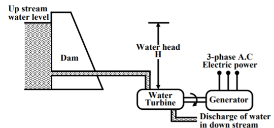
The above figure shows a hydro plant. The water from the dam is supplied to the water turbine, the potential energy is converted to kinetic energy making the turbine run. This kinetic energy from the turbine is converted to the electrical energy through generator.Water turbines generally operate at low rpm, so number of poles of the alternator are high.
Thermal Plant:
In these plants coal is burnt to produce high temperature and pressure steam in boiler. The steam produces a rotational motion when it passes through turbine. This turbine rotates and produces electricity. In India coal is present in abundance so they are commonly used. The resources used are easily available and cheap so they require less cost in installation. The main drawback of these plants is that they pollute the environment. As the coal is burnt to produce energy the leftover ash and the chimneys adds to the cost in the plant.
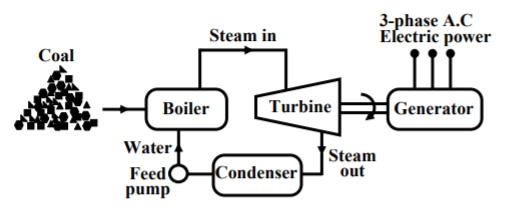
We conclude the working of thermal plant by noticing that chemical energy from coal is converted to heat and steam which the turbine converts to mechanical energy to rotate and produce electricity.
Nuclear Power Plants:
The radioactive elements like U235 and thorium are used as fuel. The nuclear reactors and heat exchanger tubes are used in place of boilers as in thermal plants.
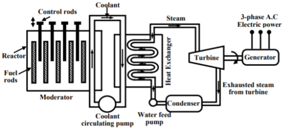
There is fission reaction takes place in the radioactive elements within the nuclear reactors. The fission reaction is a chain reaction producing huge amount of energy in the form of heat. This heat is passed to the heat exchanger tubes producing steam of very high temperature. This steam drives the turbine to produce the electricity.
Diesel power station:
The generator or alternators are moved using diesel engines to generate power. The mechanical power required for driving alternator comes from combustion of diesel engine. Due to high cost of diesel these plants are not useful for large scale. They are mainly used during power cuts in industries, hospitals and commercial buildings.
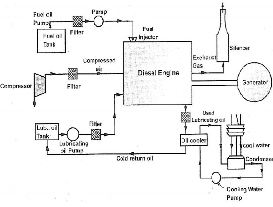
The fuel supply system in plant are storage tanks where oil is used. The strainers are used to remove solid impurities from oil before passing them to dry tank. The air intake system provides necessary air to engine for fuel combustion. Some parts in the plant have high temperatures so coolant systems are used to reduce the temperature. Compressed air is used for starting of engine.
They are simple in design and are portable. They can be stopped according to our needs. They have high thermal efficiency compared to coal. They require less space.
Non-conventional Sources: Solar energy, wind energy & energy from oceans
Solar energy:
They are also known as renewable energy sources. The energy from renewable energy sources can be used to generate power. Solar energy most easily available and free source of energy. This energy can be used in two forms solar thermal energy and solar electric energy.
I) Solar Thermal Energy: Here solar energy is converted to thermal energy with help of solar devices. They are listed below
a) Solar water heater: These water heaters use solar energy to heat water and then can be used for various purposes. They are used in hotels, dairies, industries etc. There is a solar collector mounted on roof top to take the sunlight. The tubes are attached to these collectors and liquid which needs to be heated is passed through it.The heat builds up in the collector, which is passed to the fluid passing through the tubes. There is an insulated tank to store this hot water.
b) Solar cooker: They are used to cook food using sunlight. There are of two types box type and parabolic type. The box type cooker is painted black to absorb more heat and cook the food. The parabolic type solar cooker has a collector parabolic form which accommodates cooking vessel in at its focal point. This cooker is designed to direct the solar heat to a secondary reflector inside the kitchen, which focuses the heat to the bottom of a cooking pot. It is also possible to actually fry, bake and roast food.
II) Solar Electric Energy: Here PV cells are used which are made of silicon.
a) Solar Photovoltaic: As soon as PV cells are exposed to light the electrons are released and current is produced. The cell is covered with metal grid to direct the flow of current. These cells connected in a panel are also used. These PV panels are installed above the roof. These panels are connected in series or parallel. The generation of power depends upon the amount of heat received from sun.
b) Solar water pumps: The motor required to run the pump uses electricity generated by solar panels. It consists of a photovoltaic array mounted on a stand and a motor-pump set compatible with the photovoltaic array. It converts the solar energy into electricity, which is used for running the motor pump set. The pumping system draws water from the open well, bore well, stream, pond, canal etc
Wind Energy:
Most commonly wind turbines are used. There are two types of turbines vertical axis wind turbine which has rotational vertical axis. The other is horizontal rotational axis. Wind electric generator converts kinetic energy available in wind to electrical energy by using rotor, gear box and generator. The generation of power depends upon the speed of wind. Wind turbines for remote homes (off the grid) generate DC current for battery charging. Wind turbines for remote water pumping generate 3 phase AC current suitable for driving an electrical submersible pump directly. Wind turbines suitable for residential or village scale wind power range from 500 Watts to 50 kilowatts.
Ocean Energy:
The ocean waves, tides or thermal energy provide energy to ocean. The ocean contains two types of energy thermal energy from sun and mechanical energy from tides. The oceans energy is used to produce electricity by closed loop system, open loop system or hybrid type. The oceans warm surface water is used to produce vapours from the working fluid (ammonia). The vapours produced expands and runs the turbine. The turbine than activates generator to produce electricity. Open-cycle systems actually boil the seawater by operating at low pressures. This produces steam that passes through a turbine / generator. The hybrid systems combine both closed-cycle and open-cycle systems.India has the World's largest programmes for renewable energy. Several renewable energy technologies have been developed and deployed in villages and cities of India. A Ministry of Non-Conventional Energy Sources (MNES) created in 1992 for all matters relating to Non-Conventional / Renewable Energy. Government of India also created Renewable Energy Development Agency Limited (IREDA) to assist and provide financial assistance in the form of subsidy and low interest loan for renewable energy projects.
Reference’s
1.Theory and Problems of Basic electrical Engineering : NagrathKothri
2.Electrical technology by B.L.Theraja, A.K.Theraja: S chand publication
3.Basic Electrical Engineering : V K Mehta
4.Basic Electrical Engineering : S K Sahdev: Pearson publication
5.Electrical Safety, Fire Safety engineering S.Rao, Khanna Publication