UNIT 4
Orthographic Projections
Conversion of a pictorial view into orthographic views requires sound knowledge of the principles of pictorial projection and some imagination. A pictorial view may have been drawn according to the principles of isometric or oblique projection. In either case, it shows the object as it appears to the eye from one direction only. It does not show the real shapes of its surfaces or the contour. Hidden parts and constructional details are also not clearly shown. All these must be imagined.
For converting a pictorial view of an object into orthographic views, the direction from which the object is to be viewed for its front view is generally indicated by means of an arrow. When this is not done, the arrow may be assumed to be parallel to a sloping axis. Other views are obtained by looking in directions parallel to each of the other two axes and placed in correct relationship with the front view.
When looking at the object in the direction of any one of the three axes, only two of the three overall dimensions (viz. Length, height and depth or thickness) will be visible. Dimensions which are parallel to the direction of vision will not be seen. Lines which are parallel to the direction of vision will be points, while surfaces which are parallel to it will be lines.
While studying a pictorial view, it should be remembered that, unless otherwise specified:
(i) A hidden part of a symmetrical object should be assumed to be like the corresponding visible part.
(ii) All holes, grooves etc. should be assumed to be drilled or cut right through.
(iii) Suitable radii should be assumed for small curves of fillets etc. An object in its pictorial view may sometimes be shown with a portion cut and removed, to clarify some internal constructional details. While preparing its orthographic views, such object should be assumed to be whole, and the views should then be drawn as required.
Orthographic projection
(i) It is comparatively easy to prepare a drawing from an actual object. The object is carefully examined and then placed in a suitable position for the front view. The front view of the object is selected in such a way that the maximum details of the object are visible so that the minimum dotted lines are required.
(ii) All the necessary views are then sketched freehand in a sketch book or on a pad.
(iii) Measurements of all its details and overall sizes are taken and inserted in the views, along with important notes and instructions.
(iv) Finally, a scale-drawing is prepared from these sketches.
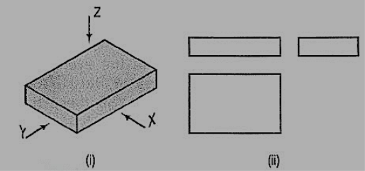
A pictorial view of a rectangular plate is given in fig. 49(i). Its front view when seen in the direction of the arrow X, side view from the left, i.e. in the direction of the arrow Y and the top view in the direction of arrow Z, are shown in fig. 49(ii).
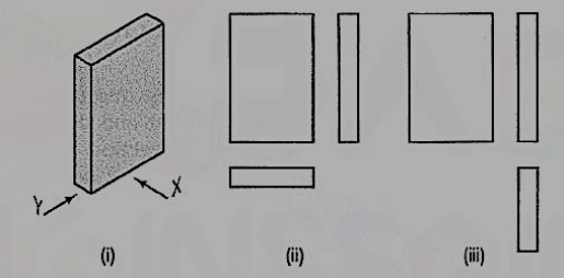
The same plate is shown in fig. 50 (i) with its longer edges vertical. Its front view looking in the direction of the arrow X, side view from the left and the top view are shown in fig. 50 (ii). These three views are similar in shape and size to the views shown in fig. 49 (ii). Only their positions and conditions have changed. Even when the front view is drawn looking in the direction of the arrow Y [fig. 50 (iii)], the three views remain similar in shape and size.
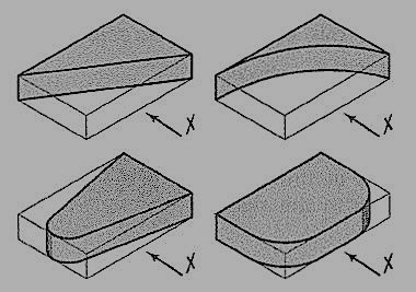
The same plate is shown cut in various shapes in fig. 51. The front view and the side view in each case will be the same as in fig. 49 (ii). The changed shapes will be seen in the top view of each plate. If these plates are kept in the position shown in fig. 50 (i), the front view in each case (looking in direction of the arrow X) will show a different shape, while the side view and the top view will be rectangles.
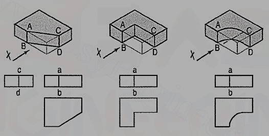
A plate cut in three different ways is shown in fig. 52. The front view in each case is the same, viz. a rectangle with a vertical line ab for the edge AB. The side view from the right in each case will be a rectangle with a vertical line cd for the edge CD. The top view in each case shows the shape of the cut.
In the front view of the plate having different shapes of grooves (fig. 53), two vertical lines are drawn for the edges of rectangular as well as semi-circular grooves.
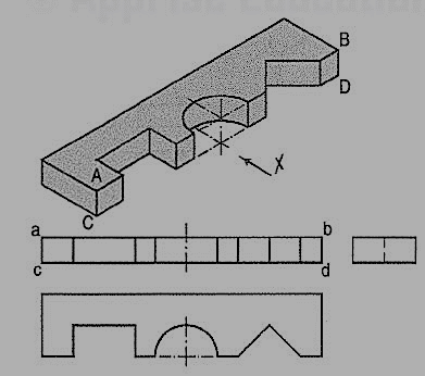
In case of the triangular groove, three vertical lines are required. Although edges AB and CD are cut, they are continuous lines ab and ed. In the top view, shapes of the grooves are seen. The grooves are not visible in the side view and hence, they are shown by a hidden line.
Two plates having grooves in upper and lower surfaces are shown in fig. 54. The shapes of the grooves are seen in the front views. In top views, two lines for the edges of rectangular as well as semi-circular grooves are drawn. For the triangular grooves, three lines are required. The tapered groove in the bottom surface is assumed to be cut throughout the width of the plate. It is not visible from above and hence; its four edges are shown by four hidden lines in the top view. In their side views, each groove should be shown by a horizontal hidden line. Therefore, the side view in this case is not necessary.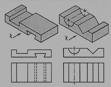
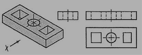
A plate having holes of different shapes is shown in fig. 55. These shapes are seen in the top view. Holes are assumed to be cut or drilled right through. They are shown by hidden lines in the front and the side views. Here also the right-side view is not necessary.
The semi-circular groove in the block shown in fig. 56 does not extend up to the opposite surface. Therefore, although the edge AB is broken, ab is a continuous line in the front view. The groove is shown by hidden lines in the side view. In the top view it is drawn as a rectangle.
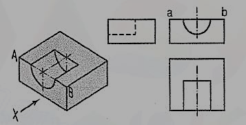
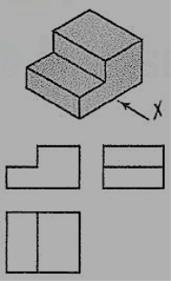
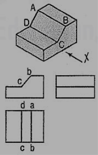
Fig. 57 shows a block in the shape of steps, along with its three views. In fig. 58, its face ABCD is inclined. Hence, in the top view, two lines ab and cd are drawn for that face.
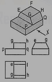
The front and back faces of the upper step are shown inclined in fig. 59. Their inclinations are shown in the side view. In the front view, the line pq for the edge PQ is drawn. In the top view, lines ef and gh for edges ff and CH are shown.
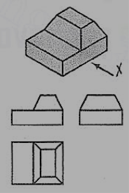
In fig. 60, all the four side-faces of the upper step are inclined. Their inclinations are seen in the front view and in the side view. In the top view, two rectangles are seen for the upper step. Lines (for the four sloping edges) joining the corners of the rectangles should also be shown.
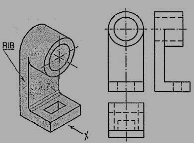
A casting having a hollow cylinder supported by a vertical rib is shown in fig. 61. The width of the rib is equal to the diameter of the cylinder. Hence, in the front view, vertical lines for the rib are tangential to the circle for the cylinder.
In the side view, the line showing the thickness of the rib vanishes just at the centre line. The rib is not visible when seen from top. Hence, it is shown by a hidden line in the top view. Note that the third view (top view) is a 'necessary' view to show the shape of rectangular slot.
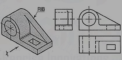
In the bearing block shown in fig. 62, the line for the rib is inclined and tangent to the semi-circle in the front view. Vanishing points for the lines for the rib in the side view and the top view are obtained by projecting the tangent-point from the front view.
From the above discussion, the following important points are to be noted:
(i) An object can be observed from six sides such as
(a) front side
(b) back side
(c) left-hand side
(d) right-hand side
(e) top side and
(f) bottom side.
It is not necessary to draw all the possible six views to describe completely the shape of the object. In practice, only those views which are necessary to describe the shape of the object should be drawn.
The view should be selected in such a way that minimum dotted lines are necessary to show internal details. The object which has both the right-hand side and left-hand side symmetrical shape requires only two views.
One of the views must be such that it completely describes the shape of the object. Refer fig. 61
(ii) Three views are necessary for the object which is not symmetrical. Refer fig. 58 and fig. 60.
(iii) The view should not be drawn out of place. That is the side view and top view are not aligned with the front view. This should be avoided.
(iv) Dotted lines must be drawn correctly as shown in table 1. Incorrect points are indicated by circle.
Table 1

(v) (a) When a visible line coincides with either a dotted line or a centre line, the visible line is shown and a centre line is extended beyond the outlines of the view.
(b) When a section-plane line coincides with a centre line, the centre line is shown and the section-plane line is drawn outside the out-lines of the object at the ends of centre line by thick dashes.
(c) When a dotted line coincides with the centre line, the dotted line should be shown.
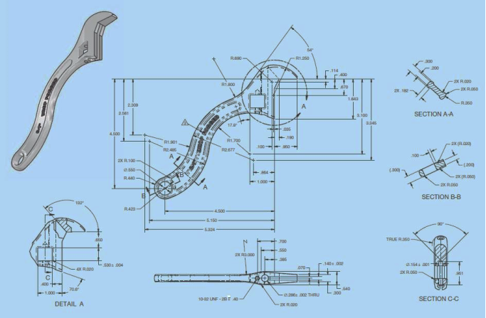
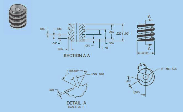
Machine element parts:
1.
2. 
3.
Reference:
- Engineering Drawing Dhananjay A.Jolhe Tata McGraw Hill Education.
- Engineering Drawing Basant Agarwal C.M Agarwal Tata McGraw Hill Education
- Engineering Drawing M.B.Shah, B.C. Rana Pearson Education, India
- A Text book of Engineering Graphics M.I. Dhabhade Association of Technical Authors, Pune.