UNIT 5
Isometric Projections
Isometric projection is a type of pictorial projection in which the three dimensionsof a solid are not only shown in one view, but their actual sizes can be measureddirectly from it.
If a cube is placed on one of its corners on the ground with a solid diagonalperpendicular to the V.P., the front view is the isometric projection of the cube. Thestep-by-step construction is shown in fig.1.
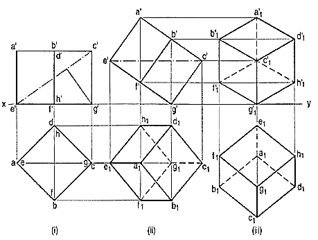
Figure 1
To draw the projections of a cube of 25 mm long edges resting on the ground on one of its corners with a solid diagonal perpendicular to the V.P., assume the cube to be resting on one of its faces on the ground with a solid diagonal parallel to the V.P.
(i) Draw a square abed in the top view with its sides inclined at 45° to xy. The line ac representing the solid diagonals AG and CE is parallel to xy. Project the front view.
(ii) Tilt the front view about the corner g' so that the line e' c' becomes parallel to xy. Project the second top view. The solid diagonal CE is now parallelto both the H.P. And the V.P.
(iii) Reproduce the second top view so that the top view of the solid diagonal,viz. e1 c1 is perpendicular to xy. Project the required front view.
Fig. 2 shows the front view of the cube in the above position, with the cornersnamed in capital letters. Its careful study will show that
(a) All the faces of the cube are equally inclinedto the V.P. And hence, they are seen assimilar and equal rhombuses instead of squares.
(b) The three lines CB, CD and CG meeting at Cand representing the three edges of the solidright-angle are also equally inclined to theV.P. And are therefore, equally foreshortened. They make equal angles of 120° with eachother. The line CG being vertical, the othertwo lines CB and CD make 30° angle each,with the horizontal.
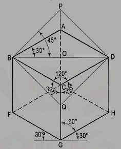
Figure 2
(c) All the other lines representing the edges of the cube are parallel to one or the other of the above three lines and are also equally foreshortened.
(d) The diagonal BO of the top face is parallel to the V.P. And hence, retains its true length.
This chapter deals with various topics of isometric projection as shown below:
1. Isometric axes, lines and planes
2. Isometric scale
3. Isometric drawing or isometric view
4. Isometric graph.
Isometric axes, lines and planes:
The three lines CB, CD and CG meeting at the point C and making 120° angles witheach other are termed isometric axes. The lines parallel to these axes are called isometriclines. The planes representing the faces of the cube as well as other planes parallel tothese planes are calledisometric planes.
Isometric scale:
As all the edges of the cube are equally foreshortened, the square faces are rhombuses. The rhombus ABCD (fig. 2) shows the isometric projection ofthe top square face of the cube in which BO is the true length of the diagonal.
Construct a square BQDP around BO as a diagonal. Then BP shows the truelength of BA.
In triangle ABO, 
In triangle PBO, 

The ratio,  .
.
Thus, the isometric projection is reduced in the ratio  , i.e. the isometric lengths are 0.815 of the true lengths.
Therefore, while drawing an isometricprojection, it is necessary to convert truelengths into isometric lengths for measuringand marking the sizes. This is convenientlydone by constructing and making use ofan isometric scale as shown below.
a) Draw a horizontal line BO of anylength (fig. 3). At the end B,draw lines BA and BP, such thatL OBA = 30° and L OBP = 45°.Mark divisions of true lengthon the line BP and from eachdivision-point, draw verticals toBO meeting BA at respective points.The divisions thus obtained on BAgive lengths on isometric scale.
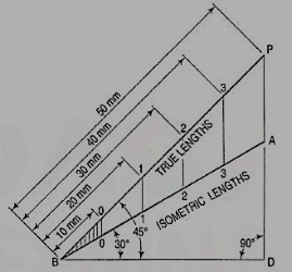
Figure 3
(b) The same scale may also be drawn with divisions of natural scale on a horizontal line AB (fig. 4). At the ends A and B, draw lines AC and BC making 15° and 45° angles with AB respectively, and intersecting each other at C.
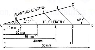
Figure 4
From division-points of true lengths on AB, draw lines parallel to BC and meeting AC at respective points. The divisions along AC give lengths to isometric scale.
The lines BO and AC (fig. 2) represent equal diagonals of a square face of the cube, but are not equally shortened in isometric projection. BO retains its true length, while AC is considerably shortened. Thus, it is seen that lines which are not parallel to the isometric axes are not reduced according to any fixed ratio. Such lines are called non-isometric lines. The measurements should, therefore, be made on isometric axes and isometric lines only. The non-isometric lines are drawn by locating positions of their ends on isometric planes and then joining them.
Isometric drawing or Isometric view
If the foreshortening of the isometric lines in an isometric projection is disregardedand instead, the true lengths are marked, the view obtained [fig. 5(iii)] will beexactly of the same shape but larger in proportion (about 22.5%) than that obtainedusing the isometric scale [fig. 5(ii)]. Due to the ease in constructionand the advantage of measuring the dimensions directly from the drawing, it hasbecome a general practice to use the true scale instead of the isometric scale.
To avoid confusion, the view drawn with the true scale is called isometricdrawing or isometric view, while that drawn with the use of isometric scale iscalled isometric projection.
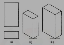
Figure 5
Referring again to fig. 2, the axes BC and CD represent the sides of a right angle in horizontal position. Each of them together with the vertical axis CG, represents the right angle in vertical position. Hence, in isometric view of any rectangular solid resting on a face on the ground, each horizontal face will have its sides parallel to the two sloping axes; each vertical face will have its vertical sides parallel to the vertical axis and the other sides parallel to one of the sloping axes.
In other words, the vertical edges are shown by vertical lines, while the horizontaledges are represented by lines, making 30° angles with the horizontal. These lines arevery conveniently drawn with the T-square and a 30°-60° set-square or drafter.
Isometric Graph:
An isometric graph as shown in fig. 6 facilitates the drawing of isometric view of an object. Students are advised to make practice for drawing of isometric view using such graphs.
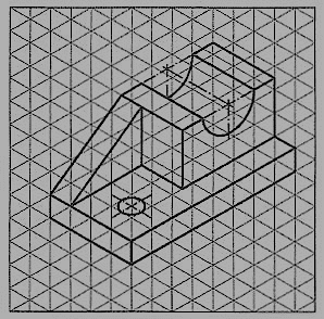
Isometric drawing of planes or plane figures:
Problem:
1. The front view of a square is given in fig. 7 (i). Draw its isometric view.
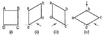
Figure 7
As the top view is a square, the surface of the square is horizontal. In isometric view, all the sides will be drawn inclined at 30° to the horizontal.
(i) From any point d [fig. 7(iv)], draw two lines da and dc inclined at 30° to the horizontal and making 120° angle between themselves.
(ii) Complete the rhombus abed which is the required isometric view.
2. Fig. 8 (i) shows the front view of a circle whose surface is parallelto the V.P.
Draw the isometric view of the circle
.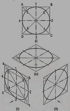
Figure 8
I. Method of points:
(i) Enclose the circle in a square, touching it in points 1, 2, 3 and 4. Draw the diagonals of the square cutting the circle in points 5, 6, 7 and 8.
(ii) Draw the isometric view of the square [fig. 8 (ii) and [fig. 8 (iii)] and on it mark the mid-points 1, 2, 3 and 4 of its sides. Obtain points 5, 6, 7 and 8 on the diagonals.
If the view given in fig. 8 (i) is the top view of a circle whose surface ishorizontal, its isometric view will be as shown in fig. 8 (iv).
As the isometric views have been drawn with the true scale, the major axis ofthe ellipse is longer than the diameter of the circle.
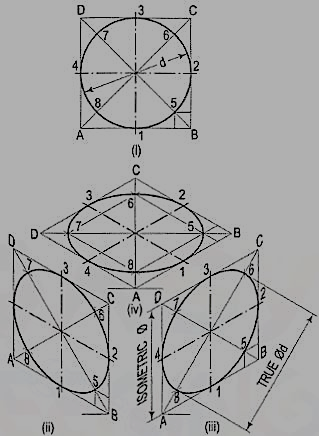
Figure 9
Fig. 9 (ii), fig. 9 (iii) and fig. 9 (iv) show the isometric projection of the circle drawn with isometric scale. Note that when the length of the side of the rhombus is equal to the isometric diameter of the circle, the length of the major axis of the ellipse is equal to the true diameter of the circle.
II. Four-center method:
Draw the isometric view of the square[fig. 10 (i)]. Draw perpendicular bisectors of thesides of the rhombus, intersecting each other onthe longer diagonal at points p and q, and whichmeet at the 120°-angles b and d.
Or, draw lines joining the 120°-angles b and d with the mid-points of the oppositesides and intersecting each other on the longer diagonal at points p and q. Two of theselines will be drawn horizontal, while the other two will make 60°-angles with thehorizontal. With centres b and d, draw arcs 3-4 and 1-2 respectively. With centres pand q, draw arcs 1-4 and 2-3 respectively and complete the required ellipse. Fig. 10 (ii)shows the ellipse obtained in the rhombus drawn in the direction of the other slopingaxis. Fig. 10 (iii) shows the isometric view of the circle when its surface is horizontal.
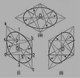
Figure 10
The ellipse obtained by the four-centre method is not a true ellipse and differs considerably in size and shape from the ellipse plotted through points. But owing to the ease in construction and to avoid the labour of drawing freehand neat curves, this method is generally employed.
Problem:
1. Fig. 11 (i) shows the front view of a semi-circle whose surface is para1lel to the V.P. Draw its isometric view.
(i) Enclose the semi-circle in a rectangle. Draw the isometric view of therectangle [fig. 11 (ii) and [fig. 11 (iii)].
(ii) Using the four-centre method, draw the half-ellipse in it which is therequired view. The centre for the longer arc may be obtained as shown orby completing the rhombus.
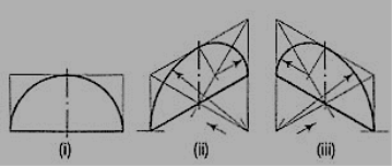
Figure 11
If the view given in fig. 11 (i) is the top view of a horizontal semi-circle, its isometric view would be drawn as shown in fig. 12 (i) and fig. 12 (ii).
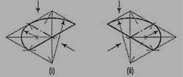
Figure 12
2. Fig. 13 (i) shows the front view of a plane parallel to the V.P. Draw its isometric view.
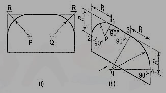
Figure 13
(i) The upper two corners of the plane are rounded with quarter circles. Enclose the plane in a rectangle.
(ii) Draw the isometric view of the rectangle. From the upper two corners of the parallelogram, mark points on the sides at a distance equal to R, the radius of the arcs. At these points erect perpendiculars to the respective sides to intersect each other at points p and q. With p and q as centres, and radii p1 and q3, draw the arcs and complete the required view.
Isometric drawings of Prisms and Pyramids:
We have seen that the isometric view of a cube is determined from its orthographicview in a position. The three edges of the solid right-angle of the cubeare shown by lines parallel to the three isometric axes. A square prism or arectangular prism also has solid right-angles. Hence, lines for its edges are alsodrawn parallel to the three isometric axes.
While drawing the isometric view of any solid, the following important pointsshould be carefully noted:
(i) The isometric view should be drawn according to the given views and insuch a way that maximum possible details are visible.
(ii) At every point for the corner of a solid, at least three lines for the edgesmust converge. Of these, at least two must be for visible edges.Lines for the hidden edges need not be shown, but it is advisable to checkup every corner so that no line for a visible edge is left out.
(iii) Two lines (for visible edges) will never cross each other.
Problem:
1. Draw the isometric view of a square prism, side of the base 20 mm long and the axis 40 mm long, when its axis is (i) vertical and (ii) horizontal.
(i) When the axis is vertical, the ends of the prism will be horizontal. Draw theisometric view (the rhombus 1-2-3-4) of the top end [fig. 14 (i)]. Its sideswill make 30°-angles with the horizontal. The length of the prism will bedrawn in the third direction, i.e. vertical. Hence, from the corners of therhombus, draw vertical lines 1-5, 2-6 and 3-7 of length equal to the lengthof the axis. The line 4-8 should not be drawn, as that edge will not bevisible. Draw lines 5-6 and 6-7, thus completing the required isometric view. Lines7-8 and 8-5 also should not be drawn. Beginning may also be made by drawinglines from the point 6 on the horizontal line and then proceeding upwards.
(ii) When the axis is horizontal, the ends will be vertical. The ends can bedrawn in two ways as shown in fig. 14 (ii) and fig. 14 (iii). In eachcase, the length is shown in the direction of the third isometric axis.
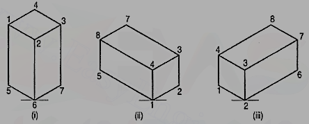
Figure 14
2. Three views of a block are given in fig. 15 (i). Draw its isometric view.
The block is in the form of a rectangular prism. Its shortest edges are vertical. Lines for these edges will be drawn vertical. Lines for all other edges which are horizontal, will be drawn inclined at 30° to the horizontal in direction of the two sloping axes as shown in fig. 15 (ii).
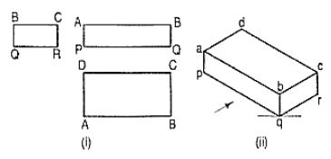
Figure 15
Methods of drawing non-isometric lines.
When an object contains inclined edges which in the isometric view would be shown by non-isometric lines, the view may be drawn by using any one of the following methods:
(i) box method or
(ii) co-ordinate or offset method.
(i) Box method: This method is used when the non-isometric lines or their ends lie in isometric planes. The object is assumed to be enclosed in a rectangular box. Initially, the box is drawn in isometric. The ends of the lines for the inclined edges are then located by measuring on or from the outlines of the box.
Problem:
1. Three views of a block are given in fig. 16 (i). Draw its isometric view.
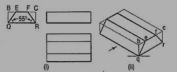
Figure 16
(i) Enclose the block in a rectangularbox.
(ii) Draw the isometric view of thebox [fig. 16 (ii)].
(iii) Mark points e and f on the line besuch that be = BE and fc = FC.
(iv) Complete the required view asshown.
2. Draw the isometricview of the frustum of the hexagonalpyramid shown in fig. 17(i).
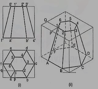
Figure 17
(i) Enclose the front view and the top view in rectangles.
(ii) Draw the isometric view of the rectangular box [fig. 17 (ii)]. Locate the six points of the base of the frustum on the sides of the bottom of the box. The upper six points on the top surface of the box are located by drawing isometric lines, e.g. P1 and Q1 intersecting at a point 1.
(iii) Join the corners and complete the isometric view as shown.
2. Co- ordinate or Offset method:
This method is adopted for objects in whichneither non-isometric lines nor their ends lie in isometric planes.
Perpendiculars are dropped from each end of the edge to a horizontal or avertical reference plane. The points at which the perpendiculars meet the plane, arelocated by drawing co-ordinates or offsets to the edges of the plane.
Problem:
1. Draw the isometric view of the pentagonal pyramid, the projections of which are given in fig. 18 (i).
(i) Enclose the base (in the top view) in an oblong.
(ii) Draw an offset oq (i.e. pq) on the line ab.
(iii) Draw the isometric view of the oblong and locate the corners of the base init [fig. 18 (ii)].
(iv) Mark a point Q on the line AB such that AQ = aq. From Q, draw a lineQP equal to qo and parallel to 2C. At P, draw a vertical OP equal to o'p'.
(v) Join O with the corners of the base, thus completing the isometric viewof the pyramid.
Fig. 18(iii) shows the isometric view of the same pyramid with its axis in horizontal position.
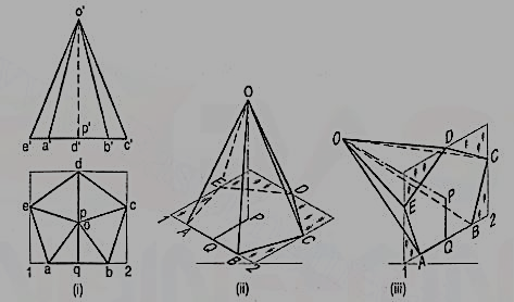
Figure 18
Isometric drawing of Cylinders:
Problem:
1. Draw the isometric viewof the cylinder shown in fig. 19 (i).
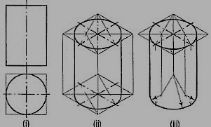
Figure 19
The axis of the cylinder is vertical; hence its ends are horizontal. Enclose the cylinder in a square prism.
Method I:
Draw the isometric view of the prism [fig. 19 (ii)]. In the two rhombuses, draw the ellipses by the four-centre method. Draw two common tangents to the two ellipses. Erase the inner half of the lower ellipse and complete the required view.
Method II:
Draw the rhombus for the upper end ofthe prism [fig. 17-27(iii)] and in it, draw theellipse by the four-centre method. From thecentres for the arcs, draw vertical lines oflength equal to the length of the axis, thusdetermining the centres for the lower ellipse.Draw the arcs for the half ellipse. Draw commontangents, thus completing the required view.
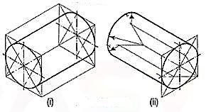
Figure 20
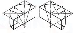
Figure 21
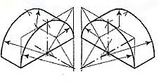
Figure 22
When the axis of the cylinder is horizontal, itsisometric view is drawn by method I as shown infig. 20 (i).
Fig. 20 (ii) shows the view drawn by method II,but the axis is shown sloping in the other direction.
Fig. 21 and fig. 22 respectively showthe isometric views (drawn by method II) of ahalf-cylindrical disc with its axis in vertical andhorizontal positions.
Isometric drawing of cones:
Problem:
1. Draw the isometricview of a cone, base 40 mm diameterand axis 55 mm long (i) when its axis isvertical and (ii) when its axis is horizontal.
(i) Draw the ellipse for the base [fig. 23 (i)]. Determine the positionof the apex by the offset method.
(ii) Draw tangents to the ellipse fromthe apex. Erase the part of theellipse between the tangents andcomplete the view as shown.
(iii) See fig. 23 (ii) which is self-explanatory.
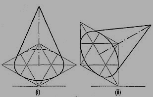
Figure 23
2. Draw the isometric view of the frustum of a cone shown in fig. 24 (i).
(i) Draw the ellipse for the base [fig. 24 (ii)]. Draw the axis.
(ii) Around the top end of the axis,draw the ellipse for the top.
(iii) Draw common tangents, erasethe unwanted part of theellipse and complete the viewas shown.
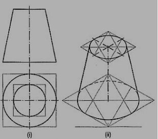
Figure 24
Isometric drawing of Sphere
The orthographic view of a sphere seen from any direction is a circle of diameterequal to the diameter of the sphere. Hence, the isometric projection of a sphereis also a circle of the same diameter as explained below.
The front view and the top view of a sphere resting on the ground are shownin fig. 25 (i). C is its centre, D is the diameter and P is the point of its contactwith the ground.
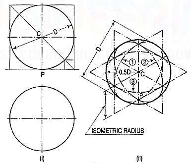
Figure 25
Assume a vertical section through the centre of the sphere. Its shape will be a circle of diameter D. The isometric projection of this circle is shown in fig. 25 (ii) by ellipses 1 and 2, drawn in two different vertical positions around the same centre C. The length of the major axis in each case is equal to D. The distance of the point P from the centre C is equal to the isometric radius of the sphere.
Again, assume a horizontal section through the centre of the sphere. Theisometric projection of this circle is shown by the ellipse 3, drawn in a horizontalposition around the same centre C. In this case also, the distance of the outermostpoints on the ellipse from the centre C is equal to O.5D.
Thus, in an isometric projection, the distances of all thepoints on the surface of a sphere from its centre, are equal to the radius of the sphere.
Hence, the isometric projection of a sphere is a circle whose diameter is equalto the true diameter of the sphere.
Also, the distance of the centre of the sphere from its point of contact withthe ground is equal to the isometric radius of the sphere, viz. CP.
It is, therefore, of the utmost importance to note that, isometric scale mustinvariably be used, while drawing isometric projections of solids in conjunction withspheres or having spherical parts.
Problem:
Draw the isometric projection of a sphere resting centrally onthe top of a square prism, the front view of which is shown in fig. 26 (i).
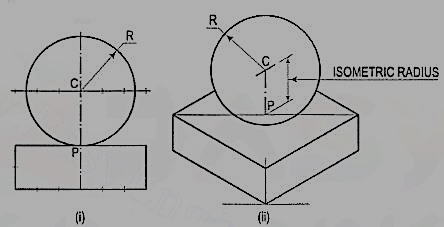
Figure 26
(i) Draw the isometric projection (using isometric scale) of the square prism and locate the centre P of its top surface [fig. 26 (ii)].
(ii) Draw a vertical at P and mark a point C on it, such that PC = the isometric radius of the sphere.
(iii) With C as centre and radius equal to the radius of the sphere, draw a circle which will be the isometric projection of the sphere.
Problems:
1. A hexagonal prism having the side of base 26 mm and the height of 60 mm is resting on one of the comer of the base and its axis is inclined to 30° to the H.P. Draw its projections and prepare the isometric view of the prism in the above stated condition.
(i) Draw the projections of the prism as shown in figure 27.
(ii) Construct the isometric view as shown in fig. 28.
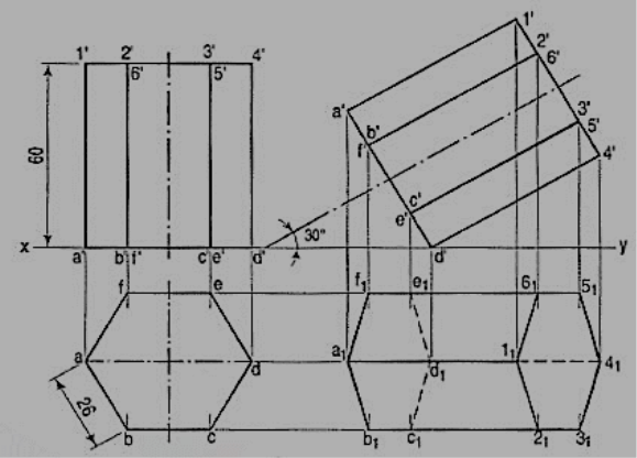
Figure 27
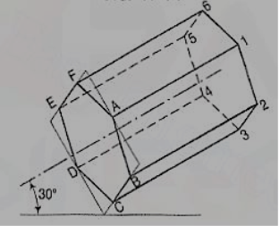
Figure 28
2.The orthographic projections of the object is shown in fig. 29. Draw the isometric view of the object.
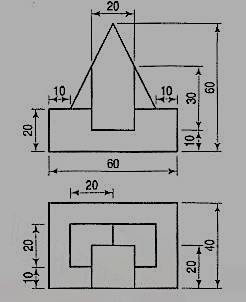
Figure 29
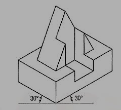
Figure 30
Reference:
- Engineering Drawing Dhananjay A.Jolhe Tata McGraw Hill Education.
- Engineering Drawing Basant Agarwal C.M Agarwal Tata McGraw Hill Education
- Engineering Drawing M.B.Shah, B.C. Rana Pearson Education, India
- A Text book of Engineering Graphics M.I. Dhabhade Association of Technical Authors, Pune.