UNIT 5
THEORY OF LIGHT AND SOUND
Introduction
LASER stands for “Light Amplification by Stimulated Emission of Radiation”.
L = Light
A = Amplification (by)
S = Stimulated
E = Emission (of)
R = Radiation
PROPERTIES OF LASER
The laser light exhibits some peculiar properties compare with the conventional light. Those are
1. Highly monochromatic
2. Highly coherence
3. Highly directionality
4. Highly intense
5. Laser Speckles
1. Highly monochromatic
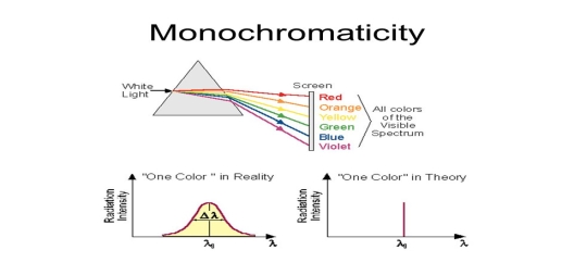
Monochromatic light means a light containing a single colour or wavelength. The photons emitted from ordinary light sources have different energies, frequencies, wavelengths, or colours. Ordinary light is a mixture of waves having different frequencies or wavelengths. The light waves of laser have a single wavelength or colour.
|
Figure 1: Monochromatic
Therefore, laser light covers a very narrow range of frequencies or wavelengths.
Hence The laser light is more monochromatic than that of a conventional light source. This may be due to the stimulated characteristic of laser light. The bandwidth of the conventional monochromatic light source is 1000 Å. But the bandwidth of an ordinary light source is 10 Å. For high sensitive laser source is 10-8 Å.
| |
|
Figure 2: Intensity- wavelength graph for light and laser
2. Highly coherence
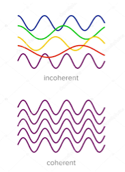
Definition:- A predictable correlation of the amplitude and phase at any one point with another point is called coherence.
|
Figure 3: Incoherence and coherence
Two waves are said to be coherent, the waves must have
In the case of conventional light, the property of coherence exhibits between a source and its virtual source whereas in the case of laser the property coherence exists between any two or more light waves.
There are two types of coherence
i) Temporal coherence
ii) Spatial coherence
Temporal coherence (or longitudinal coherence):-
The predictable correlation of amplitude and phase at one point on the wave train w. r. t another point on the same wave train, then the wave is said to be temporal coherence
To understand this, let us consider two points P1 and P2 on the same wave train, which is continuous as shown in the figure.
|
Figure 4: Wave train
Suppose the phase and amplitude at any one point is known, then we can easily calculate the amplitude and phase for any other point on the same wave train by using the wave equation
y= a sin ( (ct-x))
Where ‘a’ is the amplitude of the wave and ‘x’ is the displacement of the wave at any instant of time‘t’.
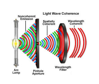
Spatial coherence (or transverse coherence) The predictable correlation of amplitude and phase at one point on the wave train w. r. t another point on a second wave, then the waves are said to be spatial coherence (or transverse coherence)
|
Figure 5: Spatial coherence
3. Highly directionality
The light ray coming from an ordinary light source travels in all directions, but laser light travels in a single direction. For example, the light emitted from torchlight spreads 1km distance it spreads 1 km distance. But the laser light spreads a few centimetres distance even it travels lacks kilometre distance.
The directionality of the laser beam is expressed in terms of divergence
∆θ =
Where r1 and r2 are the radii of laser beam spots at distances of D1 and D2 respectively from the laser source.
4. Highly Intense or Brightness
We know that the intensity of a wave is the energy per unit time flowing through a unit's normal area. Laser light is highly intense than conventional light. A one mill watt He-Ne laser is highly intense than the sun intensity. This is because of the coherence and directionality of the laser. Suppose when two photons each of amplitude a are in phase with other, then young’s principle of superposition, the resultant amplitude of two photons is 2a and the intensity is 4a2. Since in laser many numbers of photons are in phase with each other, the amplitude of the resulting wave becomes na and hence the intensity of the laser is proportional to n2a2. So 1mW He-Ne laser is highly intense than the sun.
In an ordinary light source, the light spreads out uniformly in all directions. If you look at a 100 Watt lamp filament from a distance of 30 cm, the power entering your eye is less than 1/1000 of a watt. If you look at laser beam X(caution: don’t do it at home, direct laser light can damage your eyes)X, then all the power in the laser would enter your eye. Thus, even a 1 Watt laser would appear many thousand times more intense than a 100 Watt ordinary lamp.
5. Laser Speckles
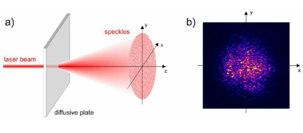
The term speckle refers to a random granular pattern that can be observed when a highly coherent light beam is diffusely reflected at a surface with a complicated structure. This phenomenon results from the interference of different reflected portions of the incident beam with random relative optical phases.
|
Figure 6: Laser Speckles
Even minor changes of the conditions, such as of the illuminated spot or the direction of the incident laser beam, can change the detailed shape of a speckle pattern.
When laser light that has been scattered off a rough surface falls on another surface, it forms an "objective speckle pattern". If a photographic plate or another 2-D optical sensor is located within the scattered light field without a lens, a speckle pattern is obtained whose characteristics depend on the geometry of the system and the wavelength of the laser.
Key Takeaways
- LASER stands for “Light Amplification by Stimulated Emission of Radiation”.
- The laser light exhibits some peculiar properties compare with the conventional light. Laser light is highly monochromatic, coherence, directionality, intense and Laser Speckles
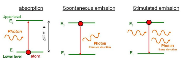
Let us discuss Einstein’s theory of the interaction of electromagnetic radiation with matter. He proposed that electromagnetic radiation interacts with matter in the following three steps.
- Stimulated Absorption
- Spontaneous Emission
- Stimulated Emission
Stimulated Absorption:
Let E1 and E2 be the energies of the ground and excited states of an atom. Suppose, if a photon of energy hν= E1− E2 interacts with an atom present in the ground state, the atom gets excitation from ground state E1 to excited state E2. This process is called stimulated absorption. Stimulated absorption rate depends upon the number of atoms available in the lowest energy state as well as the energy density photons.
Stimulated absorption rate ∝ Number of atoms in the ground state
∝ The density of photons Spontaneous emission
|
Figure 7: Interaction of Radiation with Matter
Spontaneous Emission:
Let E1 and E2 be the energies of the ground and excited states of an atom. Suppose, if a photon of energy hν= E1− E2 interacts with an atom present in the ground state, the atom gets excitation from ground stateE1 to excited state E2. The excited atom does not stay a long time in the excited state. The excited atom gets de-excitation after its lifetime by emitting a photon of energy hν= E1− E2. This process is called spontaneous emission. Also Spontaneous means by its own. Here excited atom comes to the ground state on its own so it is named as spontaneous emission.
The spontaneous emission rate depends upon the number of atoms present in the excited state.
Spontaneous emission ∝ rate number of atoms in the excited state
Stimulated Emission:
This phenomenon is responsible for producing laser light. Let E1and E2 be the energies of the ground and excited states of an atom. Suppose, if a photon of energy hν= E1− E2 interacts with an atom present in the ground state, the atom gets excitation from ground stateE1 to excited state E2. Let, a photon of energy hν= E1− E2 interacts with the excited atom within their lifetime; the atom gets de-excitation to the ground state by emitting another photon. These photons have the same phase and it follows coherence. This phenomenon is called stimulated emission.
Stimulated emission rate depends upon the number of atoms available in the excited state as well as the energy density of photons.
Stimulated emission rate ∝ number of atoms in the excited state
∝ Density of photons
EINSTEIN’S COEFFICIENTS
The distribution of atoms in the two energy levels will change by absorption or emission of radiation. Einstein introduced three empirical coefficients to quantify the change of population of the two levels. Let N1 be the number of atoms per unit volume with energy E1 and N2 be the number of atoms per unit volume with energy E2. Let ‘n’ be the number of photons per unit volume at frequency ‘υ’ such that hυ= E1− E2.
Then, the energy density of photons ρ(υ) = nhυ
|
Figure 8: Interaction of photons with atoms
When these photons interact with atoms, both upward (absorption) and downward (emission) transition occurs.
At the equilibrium, the upward transitions must be equal to downward transitions.
Upward Transition
Stimulated absorption rate depends upon the number of atoms available in the lowest energy state as well as the energy density photons. We have seen above that Stimulated absorption rate ∝ N1 i.e. Number of atoms in the ground state ∝ ρ(υ) i.e. Density of photons spontaneous emission
Stimulated absorption rate = B12N1ρ(υ) ………(1) Where B12 is the Einstein coefficient of stimulated absorption. Downward transition The spontaneous emission rate depends upon the number of atoms present in the excited state. Spontaneous emission rate ∝ N2 i.e. number of atoms in the excited state Spontaneous emission rate = A21N2 ………(2) Where A21 is the Einstein coefficient of spontaneous emission. Stimulated emission rate depends upon the number of atoms available in the excited state as well as the energy density of photons. Stimulated emission rate ∝ N2 i.e. number of atoms in the excited state ∝ ρ(υ) i.e. Density of photons Stimulated emission rate = B21N2ρ(υ) ………(3) If the system is in equilibrium the upward transitions must be equal to downward transitions. upward transitions = downward transitions B12N1ρ(υ) = A21N2 + B21N2ρ(υ) ………(4) B12N1ρ(υ) - B21N2ρ(υ) = A21N2 (B12N1- B21N2) ρ(υ) = A21N2 ρ(υ) = Divide with B21N2 in numerator and denominator in the right side of the above equation, ρ(υ) = ρ(υ) = We know from Maxwell Boltzmann distribution law
And also from Planck’s law, the radiation density ρ(υ) = Comparing the two equations (7) and (9)
The above relations are referred to as Einstein relations. From the above equation for non-degenerate energy levels, the stimulated emission rate is equal to the stimulated absorption rate at the equilibrium condition.
|
Key Takeaways
- Einstein gave his theory of the interaction of electromagnetic radiation with matter. He proposed that electromagnetic radiation interacts with matter in the following three steps. Stimulated Absorption, Spontaneous Emission and Stimulated Emission
- Stimulated absorption rate depends upon the number of atoms available in the lowest energy state as well as the energy density photons.
- The spontaneous emission rate depends upon the number of atoms present in the excited state.
- Stimulated emission rate depends upon the number of atoms available in the excited state as well as the energy density of photons.
- The Einstein relations is given as
 =
= and
and  =1
=1
Definition
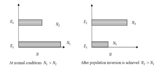
The number of atoms present in the excited state or higher energy state is greater than the number of atoms present in the ground state or lower energy state is called population inversion.
Population inversion as the name suggests that this is an inverted phenomenon. In general, the lower energy level is more populated which means it has more number atoms in the lower energy level as compared to a higher energy level. But by pumping we will obtain a state when the number of atoms present in the higher energy state is greater than the number of atoms present in the lower energy state.
Let us consider a two-level energy system of energies E1 and E2 as shown in the figure.
Let N1 and N2 be the populations that mean several atoms per unit volume of energy levels E1 and E2 respectively.
According to Boltzmann’s distribution the population of an energy level E, at temperature T is given by
Ni=N0
Where N0 is the population of the lower level or ground state and k is Boltzmann’s constant.
From the above relation, the population of energy levels E1 and E2 are
N1=N0 N2=N0 At ordinary conditions N1 >N2 i.e., the population in the ground or lower state is always greater than the population in the excited or higher states. The stage of making, the population of higher energy level is greater than the population of lower energy level is called population inversion i.e. N1 < N2
|
Figure 9: Population inversion
When the population inversion method is used to enforce more and more atoms to give up photons. This initiates a chain reaction and releasing a massive amount of energy.
This results in a rapid build-up of the energy of emitting one particular wavelength traveling coherently in a fixed direction. This process is called amplification by stimulated emission using population inversion.
This population inversion situation is essential for laser action. For any stimulated emission, the upper energy level or metastable state must have a long lifetime, i.e., the atoms should pause at the metastable state for more time than at the lower level.
Key Takeaways
- The number of atoms present in the excited state or higher energy state is greater than the number of atoms present in the ground state or lower energy state is called population inversion.
- The condition of population inversion is given as N1 < N2
- The population inversion results in a rapid build-up of the energy of emitting one particular wavelength traveling coherently in a fixed direction. This process is called amplification by stimulated emission using population inversion.
Pumping mechanisms of population inversion
A system in which population inversion is achieved is called an active system. The method of raising the particles from a lower energy state to a higher energy state is called pumping.
The process of achieving population inversion is called pumping.
This can be done in several ways.
The most commonly used pumping methods are
- Optical pumping
- Electrical discharge pumping
- Chemical pumping
- Thermal Pumping
- Injection current pumping
- Inelastic Atom-Atom Collisions
Examples of optically pumped lasers are ruby, Nd: YAG Laser(Neodymium: Yttrium Aluminium Garnet).
Electrical discharge pumping is used in gas lasers. Since gas lasers have a very narrow absorption band pumping then any flash lamp is not possible. Electric discharge refers to the flow of electrons or electric current through a gas, liquid, or solid.
In this method of pumping, electric discharge acts as the pump source or energy source. A high voltage electric discharge (flow of electrons, electric charge, or electric current) is passed through the laser medium or gas. The intense electric field accelerates the electrons to high speeds and they collide with neutral atoms in the gas. As a result, the electrons in the lower energy state gains sufficient energy from external electrons and jumps into the higher energy state
Examples of Electrical discharge pumped lasers are He-Ne laser, CO2 laser, argon-ion laser, etc.
Chemical pumping Chemical reaction may also result in excitation and hence the creation of population inversion in a few systems.
If an atom or a molecule is produced through some chemical reaction and remains excited at the time of production, then it can be used for pumping. The hydrogen fluoride molecule is produced in an excited state when hydrogen and fluorine gas chemically combine. The number of produced excited atoms or molecules is greater than the number of normal state atoms or molecules. Thus, population inversion is achieved.
Examples H2 + F2 → 2HF, in this chemical reaction, hydrogen (H2) and fluorine (F2) molecules are chemically combined to produce hydrogen fluoride molecule (2HF) in an excited state.
Thermal Pumping: Sometimes we can achieve population inversion by heating the laser medium. In thermal pumping, heat acts as the pump source or energy source. In this method, population inversion is achieved by supplying heat into the laser medium.
When heat energy is supplied to the laser medium, the lower energy state electrons gain sufficient energy and jumps into the higher energy level.
The process of achieving population inversion in thermal pumping is almost similar to the optical pumping or electric discharge method, except that in this method heat is used as a pump source instead of light or electric discharge.
Injection current pumping In semiconductors, injection of current through the junction results in creates of population inversion among the minority charge carriers.
Examples of such systems are InP and GaAs.
When high voltage electric discharge passes through a laser medium having two types of gases X and Y, the lower energy state electrons in gas X will move to the exciting state X+ similarly the lower energy state electrons in gas Y moves to the excited state Y+.
Initially, during electric discharge, the lower energy state electrons in gas X or atom X gets excited to X+ due to continuous collision with electrons. The excited state electrons in gas X+ now collide with the lower energy state electrons in gas Y. As a result, the lower energy state electrons in gas Y gains sufficient energy and jump into the exciting state Y+. This method is used in the Helium-Neon (He-Ne) laser.
THREE-LEVEL LASER
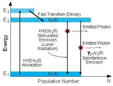
The two energy levels between which lasing occur are the lower laser energy level (E1), and the upper laser energy level (E2).
To simplify the explanation, we neglect spontaneous emission.
To achieve lasing, energy must be pumped into the system to create a population inversion. So, that more atoms will be in energy level E2 than in the ground level (E1).
Atoms are pumped from the ground state (E1) to energy level E3. They stay there for an average time of 10-8 [sec], and decay (usually with a non-radiative transition) to the metastable energy level E2.
A schematic energy level diagram of a laser with three energy levels is shown in the figure,
|
Figure 10: Energy level diagram in a three-level laser
Since the lifetime of the metastable energy level (E2) is relatively long (of the order of 10-3 [sec], many atoms remain at this level.
If the pumping is strong enough, then after pumping more than 50% of the atoms will be in energy level E2, a population inversion exists, and lasing can occur.
In a three-level system, the laser transition ends on the ground state. The unpumped gain medium exhibits strong absorption on the laser transition. A population inversion and consequently net laser gain result only when more than half of the ions (or atoms) are pumped into the upper laser level; the threshold pump power is thus fairly high.
The population inversion can be achieved only by pumping into a higher-lying level, followed by a rapid radiative or non-radiative transfer into the upper laser level, because in this way one avoids stimulated emission caused by the pump wave. (For transitions between only two levels, simultaneous pump absorption and signal amplification cannot occur.)
An example of a three-level laser medium is ruby (Cr3+:Al203), as used by Maiman for the first laser.
FOUR -LEVEL LASER
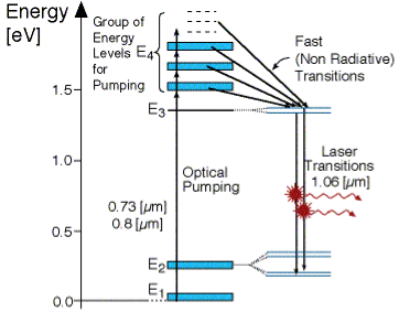
As seen in Figur, there are four energy levels, with energies E1, E2, E3, E4 with populations of N1, N2, N3, N4 respectively. There energies increase for each level so that E1 < E2 < E3 < E4.
|
Figure 11: Four level laser
In this system, optical pumping from the ground state (E1 ) into the pump band (E4) excites the atoms. From this level, the atoms decay by a fast, radiationless transition into level 3 (E3). The lifetime of the laser transition from E3 – E2 is long compared to that of E4 –E3, a population accumulates in this level 3 (lasing level).
Here the atoms relax and start to create laser transitions through spontaneous and stimulated emissions into level 2 (E2). At this level, level 4 has a fast decay into the ground state. Like before this quickly de-excited atom leads to a negligible population in E2.
This is significant, as the highly populated E3 level will then form a population inversion with the E2 level. Specifically, as long as the population of level 3 N3 is greater than 0. Therefore optical amplification and laser operation can take place.
Since only a small number of atoms need to be excited in the upper lasing level E3 to form population inversion, it proves that a 4 level laser is much more efficient and practical than a 3 level laser.
A lower threshold pump power can be achieved with a four-level laser medium, where the lower laser level is well above the ground state and is quickly depopulated e.g. by multi-photon transitions. Ideally, no appreciable population density in the lower laser level can occur even during laser operation. In that way, reabsorption of the laser radiation is avoided (provided that there is no absorption on other transitions). This means that there is no absorption of the gain medium in the unpumped state, and the gain usually rises linearly with the absorbed pump power.
The most popular four-level solid-state gain medium is Nd: YAG. All lasers based on neodymium-doped gain media, except those operated on the ground-state transition around 0.9-0.95 pm, are four-level lasers.
Neodymium ions can also be directly pumped into the upper laser level, e.g. with pump light around 880 nm for Nd: YAG. Even though effectively only three levels are involved, the term three-level system would not be used here.
Key Takeaways
- For laser action, the pumping mechanism (exciting with external source) maintain a higher population of atoms in the upper energy level relative to that in the lower level.
- A system in which population inversion is achieved is called an active system. T
- The process of achieving population inversion is called pumping.
- Pumping can be done in several ways. The most commonly used pumping methods are Optical pumping, Electrical discharge pumping, Chemical pumping Thermal Pumping, Injection current pumping , Inelastic Atom-Atom Collisions
Construction
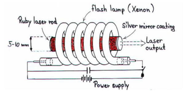
A ruby laser consists of three important elements: laser medium, the pump source, and the optical resonator.
Laser Medium
Ruby (Al2O3+Cr2O3) is a crystal of Aluminium oxide, in which 0.05% of Al+3 ions are replaced by the Cr+3 ions. The colour of the rod is pink. The active medium or laser medium in the ruby rod is Cr+3 ions. In ruby laser, 4cm length and 5mm diameter rod is generally used. The ruby has good thermal properties.
|
Figure 12: Ruby laser
The pump source
We know that population inversion is required to achieve laser emission. Population inversion is the process of achieving a greater population of a higher energy state than the lower energy state. To achieve population inversion, we need to supply energy to the laser medium i.e. to ruby crystal.
Xenon flash tube emits thousands of joules of energy in few milliseconds, but only a part of that energy is utilized by the chromium ions while the rest energy heats the apparatus. A cooling arrangement is provided to keep the experimental set up at normal temperatures.
Optical resonator
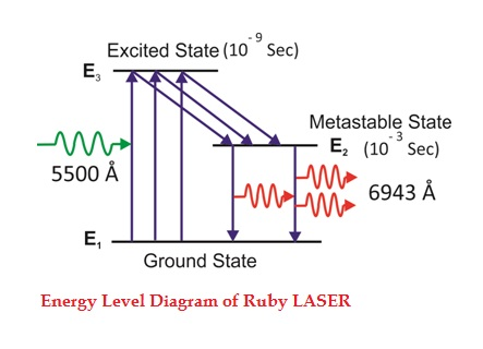
Figure 13: Energy Level diagram of ruby laser
Due to the continuous working of the flash lamp, the chromium ions are excited to a higher state E3 and returned to the E2 level. After a few milliseconds, the level E2 is more populated than the level E1 and hence the desired population inversion is achieved. The state of population inversion is not a stable one. The process of spontaneous transition is very high. When the excited chromium ion passes spontaneously from E3 to E2it emits one photon of wavelength 6943 Å. The photon reflects back and forth by the silver ends and until it stimulates an excited chromium ion in the E2 state and it to emit a fresh photon in phase with the earlier photon. The process is repeated again and again until the laser beam intensity is reached a sufficient value. When the photon beam becomes sufficiently intense, it emerges through the partially silvered end of the rod. The wavelength 6943 Å is in the red region of the visible spectrum.
The laser requires high pumping power
The efficiency of a ruby laser is very small
Application of ruby laser
- Ruby lasers are in optical photography
- Ruby lasers can be used for the measurement of plasma properties such as electron density and temperature.
- Ruby lasers are used to remove the melanin from the skin.
- Ruby laser can be used for the recording of holograms.
Key Takeaways
- Ruby laser is a three-level solid-state laser.
- A ruby laser consists of three important elements: laser medium, the pump source, and the optical resonator.
- Ruby laser is one of the few solid-state lasers that produce visible light. It emits deep red light of wavelength 694.3 nm.
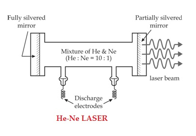
The helium-neon laser consists of three essential components:
- Pump source (high voltage power supply)
- Gain medium (laser glass tube or discharge glass tube)
- Resonating cavity
Pump source
The gain medium of a helium-neon laser is made up of a mixture of helium and neon gas contained in a glass tube at low pressure. In the He-Ne gas laser, the He and Ne gases are taken in the ratio 10:1 in the discharge tube.
Gain medium
In He-Ne laser 80cm length and 1cm diameter discharge are generally used. The out power of these lasers depends on the length of the discharge tube and the pressure of the gas mixture. Therefore, to achieve population inversion, we need to pump electrons from the lower energy state of the helium. In He-Ne laser, neon atoms are the active centres and have energy levels suitable for laser transitions while helium atoms help in exciting neon atoms.
|
Two reflecting mirrors are fixed on either end of the discharge tube, in that, one is partially reflecting and the other is fully reflecting. The fully silvered mirror will completely reflect the light whereas the partially silvered mirror will reflect most of the light but allows some part of the light to produce the laser beam.
WORKING
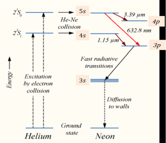
When the electric discharge is passing through the gas mixture, the electrons accelerated towards the positive electrode. During their passage, they collide with He atoms and excite them into higher levels. 23s1 and 21s0 form the ground state of the He atom. In higher levels, 23s1 and 21s0, the lifetime of He atoms are more. So there is a maximum possibility of energy transfer between He and Ne atoms through atomic collisions. When He atoms present in the levels 23s1 and 21s0 collide with the Ne atom's present ground state, the Ne atoms get excitation into higher levels 4s and 5s.
Due to the continuous excitation of Ne atoms, we can achieve the population inversion between the higher levels 4s and 5s and lower levels 3p and 4p. The various transitions 5s to 4p, 4s to 3p, and 5s to 3p leads to the emission of wavelengths 3.93μm, 1.51μm, and 6328 Å or 632.8μm.
|
Figure 15: Energy Level diagram of He-Ne Laser
ADVANTAGES OF HELIUM-NEON LASER
- The helium-neon laser emits laser light in the visible portion of the spectrum.
- High stability
- Low cost
- Operates without damage at higher temperatures
DISADVANTAGES OF HELIUM-NEON LASER
- Low efficiency
- Low gain
- Helium-neon lasers are limited to low power tasks
APPLICATIONS OF HELIUM-NEON LASERS
- Helium-neon lasers are used in industries.
- Helium-neon lasers are used in scientific instruments.
Helium-neon lasers are used in the college laboratories
Key Takeaways
- Helium-Neon laser is a type of gas laser in which a mixture of helium and neon gas is used as a gain medium.
- The helium-neon laser was the first continuous-wave laser ever constructed.
- The helium-neon laser consists of three essential components Pump source (high voltage power supply),Gain medium (laser glass tube or discharge glass tube), Resonating cavity
- The helium-neon laser operates at a wavelength of 632.8 nanometres (nm), in the red portion of the visible spectrum.
Semiconductor Laser
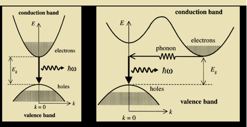
Semiconductor lasers represent one of the most important classes of lasers in use today, not only because of the large variety of direct applications in which they are involved but also because they have found widespread use as pumps for solid-state lasers.
Semiconductor lasers require, for the active medium, a direct gap material, and accordingly, the normal elemental semiconductors like Si or Ge cannot be used. The majority of semiconductor-laser materials are based on a combination of elements belonging to the third group of the periodic table such as Al, Ga, In with elements of the fifth group such as N, P, As, Sb. Examples include the best known GaAs as well as some ternary AlGaAs, InGaAs, and quaternary InGaAsP alloys.
InGaN semiconductor lasers the best candidates for semiconductor laser emission in the very important blue-green spectral region. Semiconductor laser materials are not limited to III–V compounds, however. For the blue-green end of the spectrum, we note that wide-gap semiconductors are using a combination between elements of the second group (such as Cd and Zn) and the sixth group (S, Se).
PRINCIPLE
When a p-n junction diode is forward biased, the electrons from the n – region and the holes from the p- region cross the junction and recombine with each other.
During the recombination process, the light radiation (photons) is released from a certain specified direct bandgap semiconductor like Ga-As. This light radiation is known as recombination radiation.
The photon emitted during recombination stimulates other electrons and holes to recombine. As a result, stimulated emission takes place which produces laser.
|
Figure 16: Semiconductor Laser
CONSTRUCTION
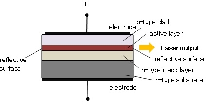
This light is not a laser yet; it is confined within the active layer because the refractive index of the clad layers is lower than that of the active layer. Besides both ends of the active layer act as a reflecting mirror where the light reciprocates in the active layer. Then, the light is amplified by the stimulated emission process and laser oscillation is generated.
The photon emission is stimulated in a very thin layer of PN junction (in order of few microns). The electrical voltage is applied to the crystal through the electrode fixed on the upper surface. The end faces of the junction diode are well polished and parallel to each other. They act as an optical resonator through which the emitted light comes out.
|
Figure 17: Construction of semiconductor Laser
WORKING
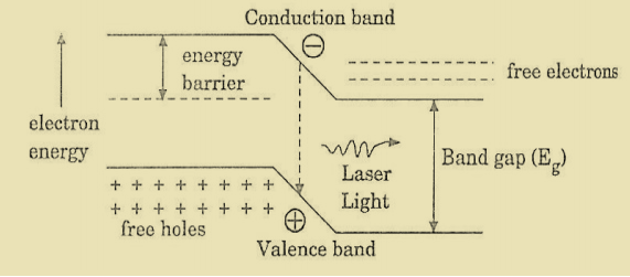
The region around the junction contains a large number of electrons in the conduction band and a large number of holes in the valence band.
If the population density is high, a condition of population inversion is achieved. The electrons and holes recombine with each other and this recombination produces radiation in the form of light.
When the forward-biased voltage is increased, more and more light photons are emitted and the light production instantly becomes stronger. These photons will trigger a chain of stimulated recombination resulting in the release of photons in phase.
|
Figure 18: Energy Level diagram of Semiconductor Laser
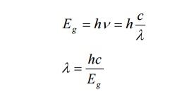
After gaining enough strength, it gives out the laser beam of wavelength 8400Å. The nature of output is a continuous wave or pulsed output. The power output from this laser is 1mW. The wavelength of laser light is given by
|
Where Eg is the bandgap energy in joule.
ADVANTAGES
- It is very small in dimension.
- The arrangement is simple and compact.
- It exhibits high efficiency.
- It is operated with lesser power than a ruby and CO2 laser.
- The laser output can be easily increased by controlling the junction current
- It requires very little auxiliary equipment
- It can have a continuous wave output or pulsed output.
DISADVANTAGES
- It is difficult to control the mode pattern and mode structure of the laser.
- The output is usually from 5 degrees to 15 degrees i.e., the laser beam has a large divergence.
- The purity and monochromaticity are power than other types of laser
- Threshold current density is very large (400A/mm2).
- It has poor coherence and poor stability.
APPLICATION
- It is widely used in fibre optic communication
- It is used to heal the wounds by infrared radiation
- It is also used as a pain killer
- It is used in laser printers and CD writing and reading.
Key Takeaways
- It is a solid-state semiconductor laser. It is a specifically fabricated p-n junction diode.
- Semiconductor laser is based on the principle that when a p-n junction diode is forward biased, the electrons from the n – region and the holes from the p- region cross the junction and recombine with each other.
- During the recombination process, the light radiation (photons) is released from a certain specified direct bandgap semiconductor like Ga-As. This light radiation is known as recombination radiation.
- The photon emitted during recombination stimulates other electrons and holes to recombine. As a result, stimulated emission takes place which produces laser.
- A semiconductor laser is a device that causes laser oscillation by flowing an electric current to the semiconductor.
- Semiconductor lasers require, for the active medium, a direct gap material, and accordingly, the normal elemental semiconductors like Si or Ge cannot be used.
OPTICAL FIBRE
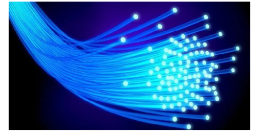
A cable that is used to transmit the data through fibres (threads) or plastic (glass) is known as an optical fibre cable. This cable includes a pack of glass threads that transmits modulated messages over light waves.
Principle: Optical Fibre works on the principle of Total Internal Reflection.
Total internal reflection:-
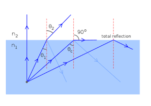
When the light ray travels from a denser medium to a rarer medium the refracted ray bends away from the normal. When the angle of incidence is greater than the critical angle, the refracted ray again reflects into the same medium. This phenomenon is called total internal reflection. The refracted ray bends towards the normal as the ray travels from a rarer medium to a denser medium. The refracted ray bends away from the normal as it travels from denser medium to rarer medium.
|
Figure 19 – Total Internal Reflection
CHARACTERISTICS OF OPTICAL FIBRE
- It has a large bandwidth.
- The optical frequency of 2 x 10¹⁴ Hz can be used and hence the system has higher bandwidth.
- Thus optical fibres have greater information-carrying capacity due to greater bandwidth.
- In an optical fibre system transmission losses are as low as 0.1 db/km.
- Optical fibre is of small size and lightweight as compared to electrical fibre.
- Optical fibre communication is free from electromagnetic interference.
- Optical fibre does not carry high voltage and current hence they are safer than electrical cable.
- Optical Fibres are flexible and have high tensile strength. Thus can be bent or twisted easily.
|
Figure 20: Optical Fibre
CONSTRUCTION OF OPTICAL FIBRE
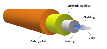
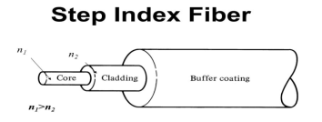
It consists of a very thin fibre of silica or glass or plastic of a high refractive index called the core. The core has a diameter of 10 um to 100 um. The core is enclosed by a cover of glass or plastic called cladding. The refractive index of the cladding is less than that of the core (which is a must condition for the working of the optical fibre). The difference between the two indicates is very small of order 10-3. The core and the cladding are enclosed in an outer protective jacket made of plastic to provide strength to the optical fibre. The refractive index can change from core to cladding abruptly (as in step-index fibre) or gradually (as in graded-index fibre).
|
Figure 21: Representation of Optical Fibre
WORKING OF OPTICAL FIBRE
When a ray of light is incident on the core of the optical fibre at a small angle, it suffers refraction and strikes the core-cladding interface, As the diameter of the fibre is very small hence the angle of incidence is greater than the critical angle. Therefore, the ray suffers total internal reflection at the core-cladding interface and strikes the opposite interface. At this interface also, the angle of incidence is greater than the critical angle, so it again suffers total internal reflection. Thus, the ray of light reaches the other end of the fibre after suffering repeated total internal reflections along the length of the fibre. At the other end, the ray suffers refraction and emerges out of the optical fibre.
We can see that the light travels in the core in a guided manner. Hence the communication through the optical fibre is sometimes referred to as an optical waveguide.
Key Takeaways
- A cable that is used to transmit the data through fibres (threads) or plastic (glass) is known as an optical fibre cable. This cable includes a pack of glass threads that transmits modulated messages over light waves.
- Principle: Optical Fibre works on the principle of Total Internal Reflection.
- It consists of a very thin fibre of silica or glass or plastic of a high refractive index called the core. The core has a diameter of 10 um to 100 um.
- The core is enclosed by a cover of glass or plastic called cladding. The refractive index of the cladding is less than that of the core.
- The core and the cladding are enclosed in an outer protective jacket made of plastic to provide strength to the optical fibre.
The types of optical fibres depend on the refractive index, materials used, and mode of propagation of light.
- The classification based on the materials used is as follows:
- Plastic Optical Fibres: The polymethylmethacrylate is used as a core material for the transmission of light.
Example:
Core: polymethyl methacrylate : Cladding: Co- Polymer
Core: Polystyrene : Cladding: Methyl methacrylate
- Glass Fibres: It consists of extremely fine glass fibres.
Example:
Core: SiO2 Cladding: SiO2
Core: GeO2- SiO2 Cladding: SiO2
- The classification based on the mode of propagation of light is as follows:
Mode of propagation:
Light propagates as electromagnetic waves through an optical fibre. All waves, having ray directions above the critical angle will be trapped within the fibre due to total internal reflection. However, all such waves do not propagate through the fibre. Only certain ray directions are allowed to propagate. The allowed directions correspond to the modes of the fibre. In simple terms, modes can be visualized as the possible number of paths of light in an optical fibre.
- Single-Mode Fibres:
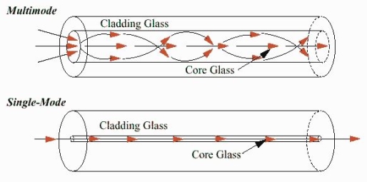
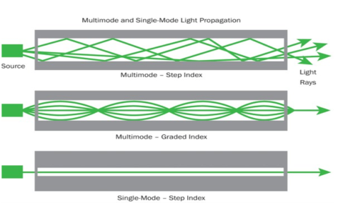
These fibres are used for long-distance transmission of signals. In general, the single-mode fibres are step-index fibres. These types of fibres are made from doped silica. It has a very small core diameter so that it can allow only one mode of propagation and hence called single-mode fibres.
The cladding diameter must be very large compared to the core diameter. Thus in the case of single-mode fibre, the optical loss is very much reduced. The structure of a single-mode fibre is given below.
Structure:
Core diameter: 5-10μm
Cladding diameter: Generally around 125μm
Protective layer: 250 to 1000μm
Numerical aperture: 0.08 to 0.10
Bandwidth: More than 50MHz km.
Application:
Because of high bandwidth, they are used in long-haul communication systems.
|
Figure 22: Single Mode and Multimode Fibre
- Multimode Fibres:
These fibres are used for short-distance transmission of signals. The multi-mode fibres are useful in manufacturing both for step-index and graded-index fibres. The multi-mode fibres are made by multi-component glass compounds such as Glass – Clad Glass, Silica – Clad – Silica, doped silica, etc. Here the core diameter is very large compared to single-mode fibres, so that it can allow many modes to propagate through it and hence called Multi-mode fibres. The cladding diameter is also larger than the diameter of the single-mode fibres. The structure of the multimode fibre is as shown in the figure above.
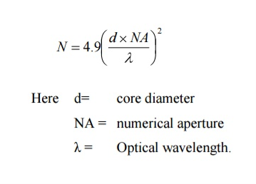
Structure: Core diameter : 50-350μm Cladding diameter : 125μm - 500μm Protective layer : 250 to 1100μm Numerical aperture : 0.12 to 0.5 Bandwidth : Less than 50MHz km. The total number of modes possible for such an electromagnetic waveguide is
Application: Because of its less bandwidth, it is very useful in short-haul communication systems.
It consists of a core surrounded by the cladding, which has a single uniform index of refraction. Step index-single mode fibres: A single-mode step-index fibre consists of a very thin core of uniform refractive index surrounded by a cladding of refractive index lower than that of the core. The refractive index abruptly changes at the core-cladding boundary. Light travels along a side path, i.e., along the axis only. So zero-order modes are supported by Single Mode Fibre.
Figure 23: Step Index Single-mode Fibres
A multimode step-index fibre consists of a core of uniform refractive index surrounded by a cladding of refractive index lower than that of the core. The refractive index abruptly changes at the core-cladding boundary. The core is of large diameter. Light follows zigzag paths inside the fibre. Many such zigzag paths of propagation are permitted in Multi-Mode Fibre. The Numerical Aperture of a Multi-mode fibre is larger as the core diameter of the fibre is larger
Figure: 24 Step index-Multimode fibres
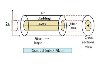
The refractive index of the optical fibre decreases as the radial distance from the fibre axis increases. GRIN fibre is one in which the refractive index varies radially, decreasing continuously in a parabolic manner from the maximum value of n1, at the center of the core to a constant value of n2 at the core-cladding interface. In graded-index fibre, light rays travel at different speeds in different parts of the fibre because the refractive index varies throughout the fibre. Near the outer edge, the refractive index is lower. As a result, rays near the outer edge travel faster than the rays at the center of the core. Because of this, rays arrive at the end of the fibre at approximately the same time. In effect light rays that arrive at the end of the fibre are continuously refocused as they travel down the fibre. All rays take the same amount of time in traversing the fibre. This leads to small pulse dispersion.
Figure 25: Graded Index Fibres
For a parabolic index fibre, the pulse dispersion is reduced by a factor of about 200 in comparison to step-index fibre. It is because of this reason that first and second-generation optical communication systems used near parabolic index fibres.
|
Key Takeaways
- The types of optical fibres depend on the refractive index, materials used, and mode of propagation of light.
- The classification based on the materials is of two type plastic optical fibres and glass fibres.
- The classification based on the mode of propagation is of two type single mode fibre and multimode fibre.
- The classification based on the refractive index is of three types step index single mode fibre, step index multimode fibre and graded index fibre.
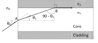
ACCEPTANCE ANGLE Definition:- Acceptance angle is defined as the maximum angle of incidence at the interface of air medium and core medium for which the light ray enters into the core and travels along with the interface of core and cladding. Let n0 be the refractive indices of air n1 be the refractive indices of core n2 be the refractive indices of cladding
Figure 26: Acceptance angle The light ray refracts into the core medium with an angle of refraction θ1 and the refracted ray AB is again incident on the interface of core and cladding with an angle of the incident (90- θ1) If (90- θ1) is equal to the critical angle of core and cladding media then the ray travels along with the interface of core and cladding along the path BC. If the angle of the incident at the interface of air and core θ1< θ0 then (90- θ1) will be greater than the critical angle. Therefore, The total internal reflection takes place. According to Snell’s law at point A n0 Sin θ0 = n1 Sin θ1 Sin θ0= (n1 / n0) Sin θ1 ………(1) According to Snell’s law at point B n1 Sin(90- θ1) = n2 Sin90 ………(2) n1 Cosθ1 = n2 as (Sin90=1) Cosθ1 = n2 /n1 Sinθ1 = (1-Cos2 θ1)1/2 Sinθ1= (1- (n2 /n1)2)1/2 Sinθ1= ( n12- n22 )1/2/ n1 ………(3) We know Sin θ0= (n1 / n0) Sin θ1 from equation (1) Substitute the value of Sinθ1 from equation (3) Sinθ0= (n1 / n0) *( n12- n22 )1/2/ n1 On simplification Sinθ0= ( n12- n22 )1/2/ n0 θ0=Sin-1 ( n12- n22 )1/2/ n0 Acceptance Angle is θ0=Sin-1 ( n12- n22 )1/2/ n0 ………(4)
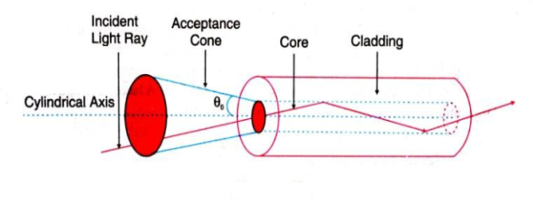
ACCEPTANCE CONE
Figure 27: Acceptance cone
NUMERICAL APERTURE NA = Sin(acceptance angle) NA = Sin {Sin-1 (( n12- n22 )1/2/ n0)} from equation (4) NA = (( n12- n22 )1/2/ n0) ………(5) If the refractive index of the air medium is unity i.e. n0=1 put in (5) NA = ( n12- n22 )1/2 ………(6) Fractional change in refractive index ∆= (n1- n2)/ n1 n1∆ = (n1- n2) ………(7) from equation (6), we have NA = {( n1- n2 )( n1+n2 )}1/2 NA = { n1∆ (n1+n2 )}1/2 as n1∆ = (n1- n2) by Eq(7) NA = { n1∆ 2n1}1/2 n1 ≈ n2, so n1+n2 =2n1 NA = n1{2∆}1/2 This gives the relation between Numerical aperture and Fractional change in refractive index. |
Key Takeaways
- Acceptance angle is defined as the maximum angle of incidence at the interface of air medium and core medium for which the light ray enters into the core and travels along with the interface of core and cladding.
- Acceptance Angle is given by θ0=Sin-1 ( n12- n22 )1/2/ n0
- In three dimensions, the light rays contained within the cone having a full angle 2θ0 are accepted and transmitted along with the fibre. Therefore, the cone is called the acceptance cone.
- Numerical aperture is defined as the light gathering capacity of an optical fibre and it is directly proportional to the acceptance angle. Numerically it is equal to the sin of the acceptance angle.
- Numerical aperture is given by NA = n1{2∆}1/2
- Optical fibres are extensively used in a communication system.
- Optical fibres are in the exchange of information between different computers
- Optical fibres are used for the exchange of information in cable televisions, space vehicles, submarines, etc.
- Optical fibres are used in the industry in security alarm systems, process control, and industrial auto machine.
- Optical fibres are used in pressure sensors in biomedical and engine control.
- Optical fibres are used in medicine, in the fabrication of endoscopy for the visualization of internal parts of the human body.
- Sensing applications of optical fibres are Displacement sensor, Fluid level detector, Liquid level sensor, Temperature/pressure sensor, and Chemical sensors
- Medical applications of optical fibres are Gastroscopy, Orthoscopic, Couldoscope, Peritonescope, and Fibrescope.
Let us discuss in detail the advantages of fibre optic communication
Optical fibre communication has more advantages than conventional communication.
1. Enormous Bandwidth
2. Low Transmission Loss
3. Electric Isolation
4. Signal Security
5. Small Size and Less Weight
6. Immunity Cross Talk
2. Low transmission loss:- The transmission loss is very low in optical fibres (i.e.KmdB/2.0) than compare with the conventional communication system. Hence for long-distance communication fibres are preferred.
3. Electric isolation:- Since fibre optic materials are insulators, they do not exhibit earth and interface problems. Hence communicate through fibre even in an electrical dangerous environment.
4. Signal security:- The transmitted signal through the fibre does not radiate, unlike the copper cables, a transmitted signal cannot be drawn from fibre without tampering with it. Thus the optical fibre communication provides 100% signal security.
5. Small size and less weight:- The size of the fibre ranges from 10μm to 50μm, which is very small. The space occupied by the fibre cable is negligibly small compared to conventional electrical cables. Optical fibres are light in weight.
6. Immunity cross-talk:- Since the optical fibres are dielectric waveguides, they are free from any electromagnetic interference and radio frequency interference. Since optical interference among different fibres is not possible, cross talk is negligible even many fibres are cabled together.
Disadvantages of Optical Fibre
The disadvantages of optical fibre include the following
- The main disadvantages of these cables are installation is expensive and difficult to fix together.
- The optical fibre cables are very difficult to merge & there will be a loss of the beam within the cable while scattering.
- Fibre optic cables are compact and highly vulnerable while fitting
- These cables are more delicate than copper wires.
- Special devices are needed to check the transmission of fibre cables.
Acoustics, the science concerned with the production, control, transmission, reception, and effects of sound. The term is derived from the Greek akoustos, meaning heard.
In audio signal processing and acoustics, echo is a reflection of sound that arrives at the listener with a delay after the direct sound.. .. The delay is directly proportional to the distance of the reflecting surface from the source and the listener.
Echo is the sound of your voice reverberating in the telephone receiver while you are talking. If the echo’s amplitude is low, it goes unnoticed, and is not problematic in the conversation; however, if the echo interval exceeds approximately 25 milliseconds (ms), it becomes audible to the speaker. The echo can be extremely disruptive to a conversation. It can so critically impair voice quality that it makes phone calls very unpleasant and distracting; very often to the point of non-comprehension of the conversation. Most echo-laden telecom transactions are quickly abandoned by the participants.
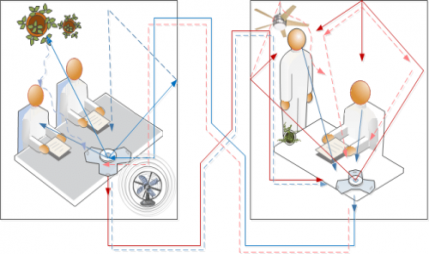
Acoustic echo originates in a local audio loopback that occurs when a microphone(s), pick up audio signals from a speaker(s) and sends them back to an originating participant. The originating participant will then hear the echo of the participant’s voice as the participant speaks.
Acoustic echo can be intensified when sensitive microphone(s) are used, as well as when the microphone and/or speaker volume is turned up to a high level, and also when the microphone and speaker(s) are positioned so that the microphone is close to one or more of the speakers. This echo is aggravated by reflective acoustic echo reflected by walls and/or objects.
Acoustic echo is a common problem with audio conferencing systems. It originates in the local audio loop-back that occurs when your microphone picks up audio signals from your speaker and sends them back to the other participant along with your voice. The other participant hears this echo of his or her voice as he or she speaks.
|
Figure 28: Acoustic echo: Local Loopback
Acoustic echo can be caused or exacerbated when very sensitive microphones are used, the speaker volume is turned up very high, or the microphone and speaker are very close to one another. Besides being annoying, this can prevent normal conversation among participants in a conference.
Acoustics in architecture means improving sound in environments. Although it is a complex science, understanding the basics - and making efficient and effective decisions - is much easier than you might think. The first step is to understand that there are two technical categories used in acoustics: soundproofing and acoustical treatment. Soundproofing means "less noise" and acoustical treatment, "better sound”.
- An appropriate reverberation time
- Uniform sound distribution
- An appropriate sound level
- An appropriately low background noise
- No echo or flutter echo
The acoustic requirement for a good auditorium is as follows-
- The initial sound should be of adequate intensity.
- The sound should be evenly distributed throughout the hall.
- The successive nodes should be clear & distinct.
- Noise has to be taken care of.
- The size & the shape of the ball have also to be taken care of.
These requirements can be achieved in the following ways-
Site/location:-Before construction the first important factor to be considered is the location. For the best acoustical quality of the hall, it should be far from railway tracks, industrial areas, airports, & highways, etc.
Size: - The size of the hall should be optimum, neither big nor small. Is the small uneven distribution of sound will take place due to the formations of stationary waves. If the size is too big reverberation time will be more that results in confusion & an unpleasant sound.
Shape: - Instead of parallel walls spade walls are preferred, curved surfaces should be built with proper care.
Reverberation: - Reverberation time (T) should be neither too small nor too large. If it is small intensity will be weak. If large sound will be unpleasant. Thick carpets curtains, upholstered chairs, audience take care of reverberation. For lecture halls, the reverberation time is approximately 0.5sec, for music concerts hall-1.5sec, for cinema theatres-2sec
Absorption: - Use of proper absorbent material enhances the quality of sound.
Echelon effect: - The regular intervals/space between staircase or railings give repeated echo, this makes the sound unpleasant, so thick carpets take care of this & wide gaps between staircases are generally preferred. No echo or flutter echoes must occur for the acoustics to be good. It is easy to prevent echo by installing a little sound-absorbing material on the wall.
Key Takeaways
- Acoustics, the science concerned with the production, control, transmission, reception, and effects of sound.
- Echo is a reflection of sound that arrives at the listener with a delay after the direct sound.
- The delay is directly proportional to the distance of the reflecting surface from the source and the listener.
- Acoustics in architecture means improving sound in environments.
- According to classic acoustics theory, there are five requirements such as an appropriate reverberation time, Uniform sound distribution, an appropriate sound level, an appropriately low background noise, No echo or flutter echo which, when met, result in good acoustics.
The reverberation is defined as the persistence of audible sound after the source has stopped emitting sound. The duration for which the sound is stopped is called reverberation time. This time is measured from the instant the source stops the emitting sound.
The time of reverberation is defined as the time taken by the sound to fall below the minimum audibility measured from the instant when the source stopped emitting sound.
According to Prof. W. C. Sabine, the standard reverberation time is defined as the time taken by sound to fall to one-millionth of its intensity just before the sound is cut off.
Absorption Coefficient = |
As all sound waves falling on an open window pass through, it can be assumed that an open window behaves as a perfect absorber of sound, and hence the standard of absorption is taken as the unit area of an open window as a standard unit of absorption.
Thus, the absorption coefficient of a material is defined as the rate of the sound energy absorbed by a certain area of the surface to that of the open window of the same area.
The absorption coefficient of a surface is defined as the reciprocal of its area which absorbs the same sound energy absorbed at a unit area of an open window.
According to W. C. Sabine, the time of reverberation depends upon 1. Size of the hall, 2. Loudness of the sound, 3. Kind of music or sound for which hall is to be used. Acoustics and Ultrasonic Reverberation Time T = 0.165 V/ T = 0.165 V/ A Where V-Volume of the hall in m3 a - Absorption coefficient S - Area of reflecting surface in a square meter
Example: A cinema hall has a volume of 7500m3. It is required to have a reverberation time of 1.5 sec? What should be the absorption in the hall? Solution: Given Volume = 7500m3 Reverberation time T = 1.5 sec We know that reverberation time is given by T = 0.165 V/ T = 0.165 V/ A Where V-Volume of the hall in m3 A - Absorption coefficient 1.5 = 0.165 x 7500/A A= 825 O.W.S
Example: A volume of the room is 1200m3. The wall area of the room is 200 m3. The floor wall area of the room is 120m3 and the ceiling area is 120m3 and. The average sound absorption coefficient (i) for walls is 0.03 (ii) for the ceiling is 0.80 (iii) for the floor is 0.06. Calculate the average absorption coefficient and reverberation time? Solution: Given Volume = 1200m3 The average absorption coefficient is A = a1s1 +a2s2 +a3s3 / s1 +s2 +s3 A = (0.03 x 200 + 0.80 x120 +0.06 x 120) / (200+120+120) A = 0.2389 =0.24 (approx.) Now the total absorption of room = As =0.24 x460 =110.40 O.W.S. Reverberation Time T = 0.165 V/AS = 0.165 x 1200/ 109.2 = 1.80 seconds
Example: For an empty hall of size 20x15x10 m3 the reverberation time is 3.5 sec. calculate the average absorption coefficient. What area of the wall should be covered by the curtain to reduce reverberation time by 2.5 sec. Given the absorption coefficient of curtain clothe is 0.5 Solution: A =as = (0.165) x (20x15x10)/ 3.5 = 138 m2 When the wall is covered with the curtain clothe 2.5 = (0.165) x (20x15x10)/ 0.5x s Therefore area of the wall covered by the curtain s = 483- (2.5 x 138) /2.5 x 0.5 110.4 m2 |
Acoustical Materials
Acoustical materials are a variety of foams, fabrics, metals, etc. used to quiet workplaces, homes, automobiles, and so forth to increase the comfort and safety of their inhabitants by reducing noise generated both inside and outside of those spaces.
Acoustical materials are used in two major ways: as soundproofing, by which noise generated from outside a given space is blocked from entering the space; and, as sound-absorbing, where noise generated within a space is reduced inside the space itself.
As an example of soundproofing, a school might construct a special wall to isolate the music room from a general classroom next door. As for sound-absorbing, a machine shop might install barriers to block and absorb the acoustic energy of a noisy air compressor.
Sound and noise are managed by four methods: blocking, absorbing, diffusing, and isolating.
- Blocking relates to the use of soundproofing.
- Absorption works by converting sound energy into heat.
- Diffusion seeks to scatter sound without deadening a room.
- Isolating is done at the source of the noise itself, by placing a compressor on isolation mounts, for instance.
ACOUSTICAL DESIGN OF A HALL
Factors affecting the acoustics of buildings and their remedies
In a hall, if the reverberation is large there are successive sounds that result in loss of clarity in hearing. However, if the reverberation is very small, the loudness is inadequate Thus the time of reverberation for a hall should neither too large nor too small. The preferred value of the time of reverberation is called optimum reverberation time. According to W. C. Sabine standard reverberation time is given by:
T = 0.165 V/ T = 0.165 V/ A Where V-Volume of the hall in m3 a - Absorption coefficient S - Area of reflecting surface in a square meter
|
The reverberation can be controlled by the following factors:
- By providing windows and ventilators which can be opened and closed to make the optimum time of reverberation
- Decorating the walls with pictures and maps
- Using heavy curtains with folds
- The walls are lined with absorbent material such as felt, fibreboard, glass wool, etc.
- Having a full capacity of audience
- By covering the floor with carpet
- By providing acoustics tiles
2. ADEQUATE LOUDNESS
With large absorption, the time of reverberation will be smaller which will minimize the chances of confusion and may go below the level of intelligibility of hearing. Hence sufficient loudness in every portion of the hall is an important factor for satisfactory hearing.
The loudness can be maintained at the desired level by:
Using large sounding boards behind the speaker and facing the audience.
Large polished wooden reflecting surfaces immediately above the speakers.
Low ceilings are also useful in reflecting the sound energy towards the audience.
By providing additional sound energy using more number of speakers
3. FOCUSING DUE TO WALLS AND CEILINGS
If there are focusing surfaces like concave, spherical, cylindrical or parabolic, etc. on the walls or ceiling or the floor of the hall, they produce a concentration of the sound into a particular region, while in some other parts no sound reaches at all. Thus there will be non- uniformity in the distribution of sound energy in the hall.
For uniform distribution of sound in the hall:
- There should be no curved surfaces. If such surfaces are present, they should be covered with absorbent material.
- The ceiling should be low.
- Arrange speaker at the focus of parabolic reflecting surface. This will help to reflect a beam of sound in the hall.
4. ECHOES
An echo is heard, when direct and reflected sound waves coming from the same source reach the listener with a time interval of about  th second. It should be avoided as far as possible by absorption.
Echoes can be avoided by:
- Covering long distant walls with a curtain or absorbent material
- Covering high ceiling with absorbent material
5. ECHELON EFFECT
A set of railings, pillars, or any regular spacing of reflected surfaces may produce a musical note due to the regular succession of the echoes of the original sound to the listener. This makes the original sound confused.
This can be avoided by:
- Covering steps with carpet
- Covering flour with carpet
- Avoid pillars in the hall
6. BALCONIES
There are chances of reflection of sound from the railing of the balcony. This may lead to the problem like echelon effect or echoes.
This can be eliminated by:
- Adjust the height to depth ratio is 2: 1
- Use grills and bars for railings instead of bricks
7. SEATING ARRANGEMENT
This is one of the factors to be taken care of at the time of arranging the seats.
It preferred to arrange:
- Seat perpendicular to the direction of sound for better audibility
- Seats must be gradually elevated to take care of absorption of sound energy by the human body.
8. EXTRANEOUS NOISE AND SOUND INSULATION
In a good hall, no noise should reach from outside. Noise may be defined as unwanted sound such as:
Outside Noise: street traffic, hammering, drilling, operating machinery, moving of furniture, electrical generator, etc.
Inside Noise: machinery, typewriters, telephone, mobiles, projector, etc.
This extraneous noise can be avoided by:
- Avoiding openings for pipes and ventilators
- Allotting suitable locations for doors and windows
- Using heavy glasses to doors and windows
- By providing double-wall construction with air space between them
- By interposing layers of some acoustical insulators
- Use of soft floor finishes e.g. carpet, rubber, etc.
- Insulating machines like refrigerators, lifts, typewriters, projector, etc.
- Constructing a small soundproof cabin for machine and office staff
- Making hall soundproof
9. FREEDOM FROM RESONANCE
If the frequency of the created sound is equal to the original sound, then the original music will be reinforced. Due to the interference between the original sounds is distorted. Enclosed air in the hall also causes resonance.
This can be avoided by:
- Using absorbing material on reflecting surfaces
- Providing decoration which includes holes in the design on an interior wall
- Using ventilators whenever necessary
Key Takeaways
- Acoustical materials are a variety of foams, fabrics, metals, etc. used to quiet workplaces, homes, automobiles, and so forth to increase the comfort and safety of their inhabitants by reducing noise.
- Acoustical materials are used in two major ways: as soundproofing, by which noise generated from outside a given space is blocked from entering the space; and, as sound-absorbing, where noise generated within a space is reduced inside the space itself.
- Sound and noise are managed by four methods blocking, absorbing, diffusing, and isolating.
ULTRASONIC WAVE
Ultra (meaning beyond) + sonic (meaning sound) = beyond the audible sound range i.e. 20kHZ
As we know Sound wave is a vibration that can be transmitted through a medium like air, water, and metals. Whereas Ultrasonic wave is defined as inaudible sound with a high frequency of range more than 20 kHz which is higher than the upper audible limit of human hearing. A healthy body can hear a soundwave of the frequency of approximately 20 kilohertz. Also, this range can vary from human to human.
In other words Sound wave which is not intended to be heard by a human is also called an ultrasonic wave.
Generally, these waves are called high-frequency waves
PROPERTIES
- The ultrasonic waves cannot travel through a vacuum.
- These waves travel with speed same as sound waves travel in any given medium.
- In a homogeneous medium, the velocity of the ultrasonic wave is constant.
- These waves can also weld some material like plastics and metals.
- They have high energy content.
- Ultrasonic waves get reflected, refracted, and absorbed just like sound waves.
- They can be transmitted over large distances without any appreciable loss of energy.
- They produce an intense heating effect when passed through a substance.
- The ultrasonic waves have a high frequency.
- Because of their smaller wavelength, Ultrasonic waves produce negligible diffraction effects.
- Ultrasonic waves can produce vibrations in low viscosity liquids.
- When the ultrasonic wave is absorbed by a medium, it produces heat because of high frequency and high energy, and that energy is used to drill and cut thin metals.
Key Takeaways
- Ultrasonic wave is defined as inaudible sound with a high frequency of range more than 20 kHz which is higher than the upper audible limit of human hearing.
- These waves are called high-frequency waves.
- The ultrasonic waves cannot travel through a vacuum.
- These waves travel with speed same as sound waves travel in any given medium.
Ultrasonic waves are produced by a Piezo-electric generator or oscillator
PIEZOELECTRIC EFFECT
In Piezoelectric “Piezo” derived from the Greek word “piezein” and the meaning of piezein is squeeze or press. So its name itself explaining the effect.
Direct Piezoelectric Effect
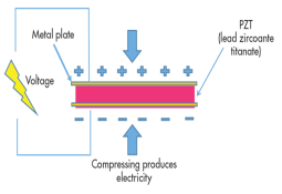
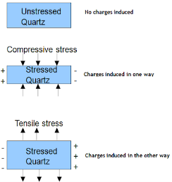
The piezoelectric effect transforms kinetic or mechanical energy into electrical energy, due to crystal deformation. When the material is compressed or squeezed, this Mechanical stress applied to the material generates electricity.
Microphones, speakers, buzzers, pressure sensors, hydrophones, and many other sensing types of devices use direct piezoelectric effect.
|
The above figure shows the direct piezoelectric effect
Figure 29: Direct Piezoelectric Effect
Inverse Piezoelectric Effect
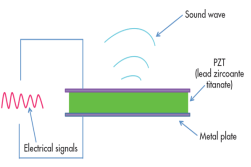
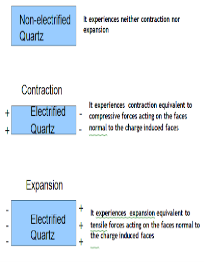
We can reverse the same effect. Inverse piezoelectric effect – when an electric field is applied to a crystal it aligns all dipoles present in the material in order. This realignment results in deformation of crystal i.e. converting electrical energy into kinetic or mechanical energy. The reversal of the piezoelectric effect is called the inverse piezoelectric effect.
Using the inverse piezoelectric effect we can develop devices that produce acoustic sound waves. Even medical ultrasound and sonar transducers use the inverse piezoelectric effect.
|
The above figure shows the inverse piezoelectric effect
Figure 30: The Inverse Piezoelectric Effect
Examples of Piezoelectric Materials
All piezoelectric materials are non-conductive for the piezoelectric effect to occur and work. Quartz is natural and first Piezoelectric Material whereas Lead Zirconate Titanate, Barium Titanate, and Lithium Niobate are man-made Piezoelectric Materials.
Piezoelectric Generator or Oscillator
Principle:
Electric circuit :
|
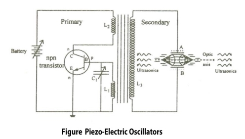
Figure 31:Piezoelectric Generator or Oscillator
Construction:
- It is a common base NPN oscillator circuit.
- Coils L1 and L2 are the primary coils of the transformer.
- Coil L2 is connected to the collector and L1 connected to the base.
- The coil L1 and variable capacitor C1 form the tank circuit of the oscillator.
- Quartz crystal is placed between the metal plates A and B to form a parallel plate capacitor.
- Quartz Crystal is connected to the secondary coil L3 of the transformer through which output or ultrasonic wave is obtained.
- The frequency of the oscillations can be changed by changing the value of capacitance.
Working:
Due to this high frequency, electric oscillations are produced in the tank circuit. The transistor is also produced by electric oscillations. This energy or oscillations is provided to the secondary coil which is again fed to the quartz crystal. Thus the oscillating electric field is converted to mechanical vibration of the crystal.
When the frequency of electric oscillations is equal to that of the natural frequency of the crystal, resonance is achieved and the sound waves of maximum amplitude are produced. Thus by using the inverse piezoelectric effect high-frequency ultrasonic waves are produced.
Condition for Resonance: Frequency of the oscillator circuit = Frequency of the vibrating crystal
Where, L1 is the inductance of the circuit C1 is the capacitance of the circuit t = Thickness of crystal slab Y = Young's Modulus of material ρ = Density of material k = 1, 2, 3. .. (Integer Multiple)
Advantages:
Disadvantages:
|
Key Takeaways
- Ultrasonic waves are produced by a Piezo-electric generator or oscillator
- The piezoelectric effect transforms kinetic or mechanical energy into electrical energy, due to crystal deformation. When the material is compressed or squeezed, this Mechanical stress applied to the material generates electricity.
- Piezoelectric Generator or Oscillator is based on the principle of inverse piezoelectric effect.
- Inverse piezoelectric effect when an electric field is applied to a crystal it aligns all dipoles present in the material in order. This realignment results in deformation of crystal i.e. converting electrical energy into kinetic or mechanical energy. The reversal of the piezoelectric effect is called the inverse piezoelectric effect.
- Condition for Resonance for Piezoelectric Generator is given as

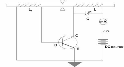
Production of Ultrasonic Wave
Ultrasonic waves are produced by the following method Magneto-striction generator or oscillator
Magneto-striction generator or oscillator
Principle: Magnetostriction effect: Magnetostriction is a property of magnetic materials like nickel or iron that causes them to change their shape or dimensions during the process of magnetization. i.e. when this material is placed in the magnetic field parallel to its length it changes its dimensions. This is called the Magnetostriction effect.
Figure
|
Figure 32:Magneto-striction generator or oscillator
Construction
- In the above figure, we are using NPN Transistor
- In which battery is connected in such a way that emitter is forward biased and collector is reverse biased.
- Current can be produced by applying necessary biasing to the transistor with the help of the battery.
- The current produced in a circuit can be noted by the mill ammeter connected across the coil L.
- The ends of the ferromagnetic rod A and B are wound by the coils L1 and L.
- The coil L1 is connected to the base of the NPN transistor The coil L is connected to the collector of the NPN transistor as shown in the figure.
- The frequency of the oscillatory circuit (LC) can be adjusted by the condenser C.
Working
When the rod is vibrating and the coil is wounded over a vibrating rod, An emf is induced in coil L, this induces an emf to coil L1 & a part of it is feed as input to the base. Hence, this feedback system makes the transistor operates continuously. The e.m.f. induced in the coil called a converse Magnetostriction effect. In this way, the current is maintained in the transistor so as the vibrations.
The frequency of the oscillatory circuit is adjusted by the condenser C and when this frequency is equal to the frequency of the vibrating rod, resonance occurs. At resonance, the rod vibrates longitudinally with larger amplitude producing ultrasonic waves of high frequency along both ends of the rod.
Condition for resonance
Frequency of the oscillatory circuit = Frequency of the vibrating rod

Where,
L is the inductance of the circuit
C is the capacitance of the circuit
l is the length of the rod.
E is the young’s modulus of the material of the rod.
ρ is the density of the material of the rod.
Advantages
- This Oscillatory circuit is simple to construct.
- Magnetostrictive materials are easily available at a low cost
- Large output power can be generated by using this method.
Disadvantages
- It can produce frequencies up to 3 MHz only.
- As rod depends on temperature and the degree of magnetization so it becomes difficult to get a constant single frequency.
- As the frequency is inversely proportional to the length of the vibrating rod, so if you increase the frequency, the length of the rod gets decreased which is practically impossible.
Key Takeaways
- Ultrasonic waves are produced by Magneto-striction generator or oscillator
- Magneto-striction generator or oscillator based on the principle of Magnetostriction effect.
- Magnetostriction is a property of magnetic materials like nickel or iron that causes them to change their shape or dimensions during the process of magnetization. i.e. when this material is placed in the magnetic field parallel to its length it changes its dimensions. This is called the Magnetostriction effect.
- Condition for resonance for Magneto-striction generator is given by

Used in Medical applications
- Ultrasonic waves are used to treat patients having a stone in the kidney. This high frequency and lower wavelength wave used to break kidney stones into tiny pieces that can be easily flushed out through urine.
- Ultrasonic waves are used in echocardiography.it is used to capture the images of the heart and its features and detect the problems associated with the heart.
- Ultrasonic waves are used in Ultrasound scans/Ultrasonography. It is very commonly used to capture images of internal body organs such as the liver, kidney, and uterus. It helps to diagnose and helps in treating the problems of the patient. In this method, ultrasound waves are made to travel through the body to the organ. They get reflected from the organ which is to be diagnosed and then these waves converted to electrical signals which can be monitored on a screen.
- Ultrasonography is used to observe the growth of the fetus inside the uterus.
- Ultrasonic waves are used to treat patients having a stone in the kidney. These high-frequency waves are used to break kidney stones into tiny pieces that can be easily flushed out through urine.
Used in Industrial Applications
- Ultrasound is used to clean internal parts of the machine Because of the high frequency of the waves, the dust particles just fall out.
- It is used to detect defects, flaws, cracks in machine parts, bridges, buildings, etc. the presence. The ultrasound waves are reflected from the cracks indicating a defect.
Used in SONAR (Sound Navigation and Ranging)
- SONAR is a device that uses ultrasonic waves to measure distances that are practically impossible to measure - the depth of the ocean, distance, and direction of underwater objects.
- SONAR comprises an ultrasound transmitter and detector fitted in a ship. The transmitter transmits ultrasonic waves which travels to the bottom of the ocean and comes back and detected.
Used in Food Processing
- In recent years, Ultrasonic waves are also used in food processing
Reference Books
I. Engineering physics- Gaur and Gupta, & S.Chand Publication
2. Engineering physics - Avadhanalu and Kshirsagar, S.Chand Publication
3. Fundamentals of optics-Jenkins and White. McGraw Hill Publication
4. A Text Book of Optics Subrahmanyam, BrijIal, S. Chand Publication
5 Optics by Ajay Ghatak
6. Engineering physics- Hitendra K Malik, A.K.Singh, Tata McGraw Hill Education Private Limited, New Delhi
