Unit – 3
Surveying
The two principles are
1. LOCATION OF A POINT BY MEASUREMENT FROM TWO POINTS OF REFERENCE:
The relative positions of the points to be surveyed should be located by taking measurement from at least two points of reference. Points of reference are points whose position is already fixed
2. SECOND PRINCIPLE IS TO WORK FROM WHOLE TO PART:
It is very essential to establish first a system of control points and to fix them with higher precision. Minor control points can be established by less precise methods and the details can be located using these minor control points by running minor traverses.
- Linear Measurements
The determination of the distance between two points on the surface of the earth is one of the basic operations of surveying. Measurement of horizontal distances or measuring linear measurement is required in chain surveying, traverse surveying and other types of surveying.
Methods of making linear measurements
Direct methods
In the direct method, the distance is actually measured during field work using a chain or a tape. This is the most commonly used method for linear measurements.
Optical methods
In the optical methods, principles of optics are used. The distance is not actually measured in field but it is computed indirectly. The instrument used for making observations is called tacheometer.
E.D.M methods
Electronic Distance Measuring (E.D.M) instruments have been developed quite recently.
These are practically replacing the measurement of distances using chains or tapes. There is a large variety of such instruments and depending upon the precision required the instruments should be used.
- Angular Measurements
There are two methods for angular measurement:
1) Triangulation Survey
2) Traverse Survey
Triangulation Survey
In the past it was difficult to accurately measure very long distances, but it was possible to accurately measure the angles between points many kilometres apart, limited only by being able to see the distant . This could be anywhere from a few kilometres, to 50 kilometres or more. Triangulation is a surveying method that measures the angles in a triangle formed by three survey control points. Using trigonometry and the measured length of just one side, the other distances in the triangle are calculated.
Traverse Survey
Traversing is that type of survey in which a number of connected survey lines form the framework and the directions and lengths of the survey lines are measured with the help of an angle measuring instrument and a tape or chain respectively.
Base line
BASE LINE :
The line on which the framework of the survey is built is known as the ‘base line’. It is the most important line of the survey . Generally, the longest of the main survey line is considered as the base line. This line should be measured very carefully and accurately. In fig. BD is the base line.
Offsets
An offset is the lateral distance of an object or ground feature measured from a survey line.
There are two types of offsets
- Perpendicular offset: The angle of offset from a point on a chain line is 900
- Oblique offset : When the angle of offset is other than 900 .
- The plane table surveying is one of the fastest and easiest methods of surveying. Plotting of plans and field observations can be done at the same time in plane table surveying. It is useful for the following cases:
- It is best fitted for small-scale surveying i.e. any types of fields
- It is also used in surveying industrial areas where compass survey fails to perform
- It is often used to fill in details between stations fixed by triangulation method or theodolite traversing method.
Temporary Adjustments of The Plane Table
1. Centering
This process is to ascertain that the point on the ground is represented accurately on the paper. It is carried out with the help of plumbing fork and plumbing bob. The pointed end (at the upper hand) of the plumbing fork is kept on paper and at the other end, a plumb bob is fixed. The board is shifted manually until the bob hangs exactly over the peg of the station. This work can be tiresome but a prerequisite for any further activities.
2. Levelling
- Leveling is done so that the drawing board remains parallel to the ground. It is done in the following three methods:
- Ordinary tilting the board by ball and socket arrangement orby adjusting the legs of the tripod.
3. Orientation
The process by which the position occupied by the board at various survey stations are kept parallel is known as the orientation. In the plane table surveying, the whole table needs to be moved at several stations to complete a survey. Every time the table is moved one has to make sure that the new station is parallel to the previous one otherwise the lines drawn on paper will not represent the same lines on the field. Methods of orientation are:-
4. Orientation by Magnetic Needle:
This method is used when it is not possible to bisect the previous station from the new station. This method is not much reliable and prone to errors due to variations of the magnetic field.
5. Orientation by Back Sighting:
This is a more reliable method. In this method, a particular line drawn from the previous station is drawn again from the new station. This process is called back-sighting. One does not necessarily have to draw the line the second time rather check if the new line superposes over the previous one or not.
Methods of Plane Table Surveying
Radiation
Method It is the simplest method of plane table surveying. This method is only effective if the whole surveying is to be done from one single station i.e. the table will be in such a position from where all the other points of the field are easily visible.
The procedure is as follows:
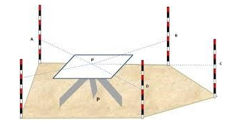
- A point P is to be selected in such a fashion that all the other points ( A B C D E) are seen easily from P.
- Centering, levelling, and orientation must be done prior to surveying.
- At first, by putting the alidade on point P a line of sight for station A is to be drawn.
- After measuring the distance of PA on field, the measurement needs to be put on paper to a suitable scale.
- Similarly, points b, c, d, and e are obtained on paper by drawing lines of sight for stations B, C and D and measuring the distances PB, PC, PD and PE on ground respectively.
- Points a, b, c, d, and e are joined on paper, as shown in the figure.

Intersection
Method In previous method it was possible to measure every distance on the field manually. In case of a mountainous terrain or rough surface where distances cannot be taken physically, it is best to use intersection method.
The procedure is:
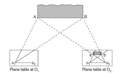
- Two stations O1 and O2 are selected so that the points to be located on paper are easily seen from them.
- The baseline (o1o2) is plotted on the paper. This is done in the way below: The table can be centered and levelled at station O1 and then after orienting at station O2, the distance O1 O2 can be accurately measured and put up to some scale on the paper. The line o1o2 can be drawn to some scale on the paper and then the board can be adjusted from station O1 by back sighting at station O2.
- From station O1, rays for stations A, B are drawn etc.
- Now moving the table to the new station and orienting it again the rays of stations A, B are drawn etc.,
- The intersection of rays from stations O1 and O2 will give points a, b etc. on paper, as shown in the figure.

Traversing Method
This is more or less like the compass survey. It is used for running survey lines between stations, which have been previously fixed by other methods of survey, to locate the topographic details.
The procedure is:
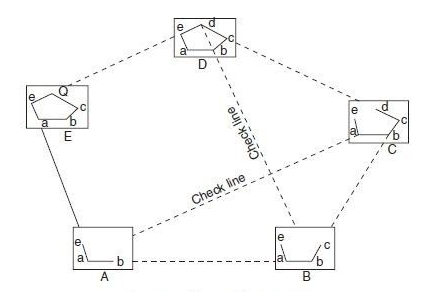
- The plane table is fixed at a location (say A)
- From that point, a sight is taken toward B and the distance AB is measured.
- The plane table is shifted to station B and sighted toward A (this is called back sighting). Distance BA was measured.
- The average distance between AB and BA are plotted to suitable scale on the drawing paper.
- Then the point C is sighted from B and the distance was measured. This process is repeated for all the stations.
- Conduct some check at uniform intervals. Finally, plot the traverse lines on the drawing sheet. Notice that back sighting was done only for the first two stations.

Resection Method
This method is suitable for establishing new stations at a place in order to locate missing details. It is the process of determining the previously plotted position of any peg station, by means of sight taken towards known points, the location of which has been plotted.
Resection method involves two different procedures as follows:
- The three-point problem
- The two-point problem
Levelling is defined as “an art of determining the relative height of different points on, above or below the surface
Principle of Levelling
The principle of levelling is to obtain horizontal line of sight with respect to which vertical distances of the points above or below this line of sight are found.
Object of levelling
- To Find the elevation of given point with respect to some assumed reference line called datum.
- To establish point at required elevation respect to datum.
Bench Mark (B.M.)
It is a fixed reference point of known elevation with respect to datum. These are very important marks. They serve as reference points for finding the RL of new points or for conducting levelling operations in projects involving roads, railways, etc.
There are 4 kinds of bench marks
- GTS (Great trigonometrically survey bench mark)
- Permanent bench mark
- Arbitrary bench mark
- Temporary bench mark
Reduced Level (RL) :
- The vertical distances or Height or depth of a point above or below the assumed datum is called Reduced level. It may be positive or negative.
- An imaginary line on the ground surface joining the points of equal elevation is known as contour. In other words, contour is a line in which the ground surface is intersected by a level surface obtained by joining points of equal elevation.
Contours
A contour is an imaginary line on the ground that passes through points having the same elevation.
Characteristics of contour lines .
- Contour lines are continuous.
- Contour lines are relatively parallel unless one of two conditions exists.
- A series of V-shape indicates a valley and the V’s point to higher elevation.
- A series U shape indicates a ridge. The U shapes will point to lower elevation.
- Evenly spaced lines indicate an area of uniform slope.
- A series of closed contours with increasing elevation indicates a hill and a series of closed contours with decreasing elevation indicates a depression.
- Closed contours may be identified with a +, hill, or -, depression.
- Closed contours may include hachure marks. Hachures are short lines perpendicular to the contour line. They point to lower elevation.
- The distance between contour lines indicates the steepness of the slope. The greater the distance between two contours the less the slope. The opposite is also true.
- Contours are perpendicular to the maximum slope.
- A different type of line should be used for contours of major elevations. Common practice is to identify the major elevations lines, or every fifth line, with a bolder, wider, line
Reference Books
- Surveying and Levelling by Kanetkar T. P. Et al
- Basic Civil Engineering by Gopi Satheesh,