UNIT 4
Basic Mechanical Engineering
Mechanical Engineering, as its name suggests, deals with the mechanics of operation of mechanical systems. This is the branch of engineering which includes design, analysis, testing, manufacturing and maintenance of mechanical systems. The mechanical engineer may design a component, a machine, a system or a process. Mechanical engineers will analyse their design using the principles of motion, energy, and force to ensure the product functions safely, efficiently, reliably, and can be manufactured at a competitive cost.
Mechanical engineering plays a dominant role in enhancing safety, economic vitality, enjoyment and overall quality of life throughout the world. Mechanical engineers are concerned with the principles of force, energy and motion.
Mechanical engineering is a diverse subject that derives its breadth from the need to design and manufacture everything from small individual parts and devices (e.g. Micro scale sensors and inkjet printer nozzles) to large systems (e.g. Spacecraft and machine tools). The role of a mechanical engineer is to take a product from an idea to the marketplace. In order to accomplish this, a broad range of skills are needed. Since these skills are required for virtually everything that is made, mechanical engineering is perhaps the broadest and most diverse of engineering disciplines.
Mechanical engineers play a central role in such industries as automotive (from the car chassis to its every subsystem—engine, transmission, sensors); aerospace (airplanes, aircraft engines, control systems for airplanes and spacecraft); biotechnology (implants, prosthetic devices, fluidic systems for pharmaceutical industries); computers and electronics (disk drives, printers, cooling systems, semiconductor tools); micro electromechanical systems (MEMS) (sensors, actuators, micro power generation); energy conversion (gas turbines, wind turbines, solar energy, fuel cells); environmental control (HVAC, air-conditioning, refrigeration, compressors); automation (robots, data and image acquisition, recognition, control) and manufacturing (machining, machine tools, prototyping, micro fabrication).
The main areas of study in this branch are:
- Materials
- Solid and fluid mechanics
- Thermodynamics
- Heat transfer
- Control, instrumentation
- Specialized mechanical engineering subjects include biomechanics, cartilage-tissue engineering, energy conversion, laser-assisted materials processing, combustion, MEMS, micro fluidic devices, fracture mechanics, nanomechanics, mechanisms, micro power generation, tribology (friction and wear) and vibrations.
Zeroth Law of thermodynamics
If two systems are each in thermal equilibrium with the third system then the two system are in thermal equilibrium which each other.
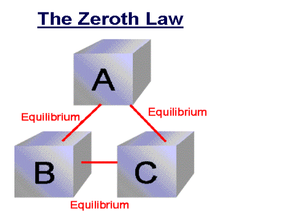
When a body A is in thermal equilibrium with a body B , and also separately with a body C ,then B and C will thermal equilibrium with each other .this is known as the Zeroth law of thermodynamics.
First law of Thermodynamics
Sometimes our body start to sweat and feel warm when we are in a room full of people and the sweating becomes excessive if the room size is small. This happens because our body is trying to cool off hence heat transfers from our body in the form of ‘sweat’. This entails the first law of thermodynamics.
The first law of thermodynamics states that the total energy of an isolated system is constant. Energy can be transformed from one form to another, but can neither be created nor destroyed.
According to this law, some of the heat given to system is used to change the internal energy while the rest in doing work by the system. Mathematically,
ΔQ=ΔU+ΔW
Where,
ΔQ = Heat supplied to the system
ΔW= Work done by the system.
ΔU = Change in the internal energy of the system.
If Q is positive, then there is a net heat transfer into the system, if W is positive, then there is work done by the system. So positive Q adds energy to the system and positive W takes energy from the system.
It can also be represented as ΔU=ΔQ−W
We can say that internal energy tends to increase when heat is given to the system and vice versa.
Limitations of First Law of Thermodynamics
- The limitation of the first law of thermodynamics is that it does not say anything about the direction of flow of heat.
- It does not say anything whether the process is a spontaneous process or not.
- The reverse process is not possible. In actual practice, the heat doesn’t convert completely into work. If it would have been possible to convert the whole heat into work, then we could drive ships across the ocean by extracting heat from the water of the ocean.
Second law of thermodynamics
Kelvin-Planck statement
It is impossible to convert all the heat extracted from a hot body into work. In the heat engine, the working substance takes heat from the hot body, converts a part of it into work and gives the rest to the cold body. There is no engine that can convert all the heat taken from the source into work, without giving any heat into the sink. This means that for obtaining continuous work, a sink is necessary.
Clausius statement
It is not at all possible to transfer heat from a cold body to a hot body without the expenditure of work by an external energy source or its states that the heat energy cannot transfer from a body at a lower temperature to a body at a higher temperature without the addition of energy.
For example - There is a refrigerator that transfers an amount of heat from a cold body to a hot body without having any supply of external energy. So this is the violation of Clausius statement. Now suppose an engine working between the same hot and cold bodies takes in heat from hot body converts a part W into work and gives the remaining heat to the cold body. The engine alone does not violate the second law of thermodynamics. But if the engine and refrigerator combine together, they form a device that takes up all the heat from the hot body and converts all into work without giving up any amount to the cold body. It violets the Kelvin-Planck statement. So we say that the two statements of the second law of thermodynamics are equal in all respects
IC Engines:
Internal combustion (IC) engines- the fuel used undergoes combustion inside the engine in the presence of air. The product produced by the combustion becomes the working fluid of the engine.
Internal combustion engines have higher efficiency and are lighter in weight in comparison to the power developed. They have become very much suitable for mobile applications. With all these advantages, IC engines have become universal means of power generation and very much popular.
Classification of Internal Combustion (IC) Engine:
Internal combustion engines may be classified on the basis of:
- Thermodynamic cycle used – Otto cycle, diesel cycle, and dual cycle engine
- Fuel used – Petrol engine, diesel engine, gas engine, and kerosene oil engine
- Number of strokes for completion of cycle – Four-stroke engine and two-stroke engine
- Types of fuel ignition – Spark ignition (SI) and compression ignition (CI)
- Number of cylinders – Single cylinder engine and multi-cylinder engine
- Position of cylinders – Horizontal, vertical, V-engine, and radial engine
- Method of cooling engines – Air-cooled engine and water-cooled engine
Components of Internal Combustion (IC) Engine:
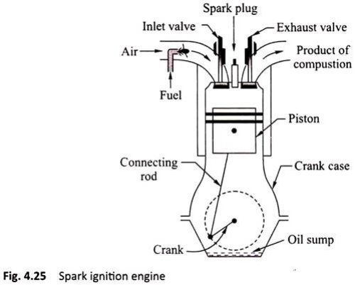
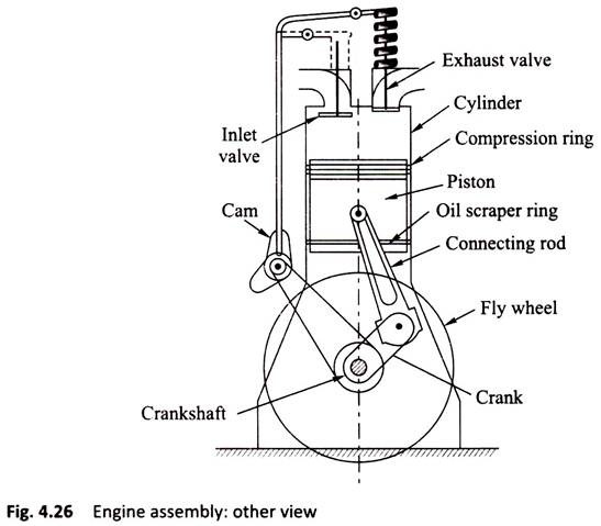
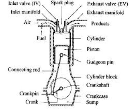
An assembled diagram with various parts of an IC engine is shown in Figure
i. Engine Cylinder:
It is a cylindrical vessel in which the fuel is burnt and the product of combustion gets expanded to develop power. Inside the cylinder, there is a sleeve fitted called the cylinder liner of hard metal. A piston makes reciprocating motion inside the cylinder.
Ii. Cylinder Head:
It is fitted at the top of cylinder to cover the cylinder. The cover provides the accommodation of inlet valve, exhaust valve, and spark plug (in SI engine) or injector (in CI engine).
Iii. Piston:
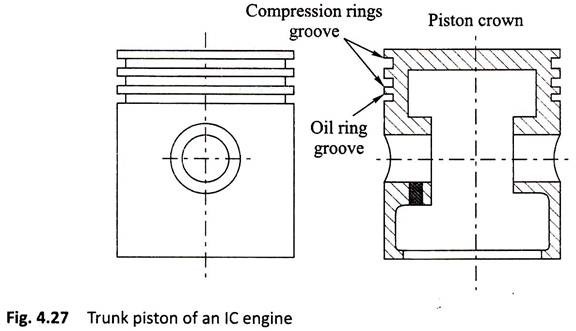
Piston is a tightly fitted block generally known as trunk piston which receives the gas pressure inside the engine cylinder. The gas pressure is transmitted to the crankshaft through the connecting rod (Fig. 4.27).
Piston Rings:
There are two types of rings fitted on the circumferential groove provided on the outer surface of piston (Fig. 4.28):

Compression Ring:
Compression rings maintain a gas tight contact between cylinder and the piston.
Oil Scraper Ring:
Lubrication is required in the cylinder sleeve surface to reduce frictional forces. However, the excess oil needs to be removed. Thus, the ring will have a groove which removes this excess lubricating oil from the sleeve of the cylinder into the crank case.
Connecting Rod:
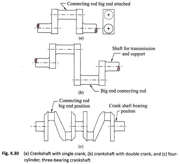
Connecting rod transmits the force from piston to crankshaft. It helps in converting the reciprocating motion to rotary motion. It has two ends—small end and big end. The small end is connected with piston with a gudgeon pin. The big end is connected with crankshaft (Fig. 4.29).

Crank and Crankshaft:
It converts the reciprocating motion of the piston to rotary motion of the shaft. The crankshaft is enclosed inside a crank case [Figs. 4.30(a) – 4.30(c)].
Valves:
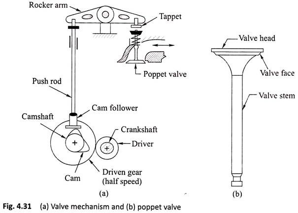
These valves are also called poppet valves.
There are two types of valves:
i. Suction valve and
Ii. Exhaust valve.
i. Suction Valve:
This valve controls the mixture of petrol vapors and air in SI engines and only air in CI engines.
Ii. Exhaust Valve:
It controls the flow of exhaust gas from the cylinder. The product of combustion is to be expelled out by opening this valve for starting fresh cycle.
The valves are operated by cam mechanism with the help of rocker arms in a single cylinder engine and by camshaft in a multi cylinder engine [Figs. 4.31(a) and 4.31(b)]. In four-stroke engines, the rotation of the camshaft is half of rotation of the crankshaft.
Fly Wheel:
Fly wheel is a heavy wheel mounted on engine shaft. It has large moment of inertia and, hence, absorbs energy during operation and supplies back the energy to the engine when required. Thus, this removes the cyclic fluctuation and maintains uniform rotation of the crankshaft. A single cylinder engine will have a large fly wheel, whereas a multi cylinder engine will have a smaller fly wheel.
Crank Case:
It is fitted in the lower part of the engine cylinder to cover crankshaft and also to store the lubricating oil known as oil sump.
2 Two stroke.
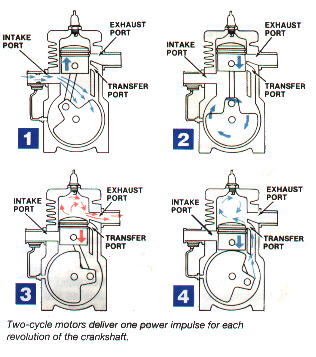
In two stroke engine the working cycle is completed in two stroke of the piston or one revolution of crankshaft. This is achieved by carried out suction and compression in one stroke expansion and exhaust in the second stroke.
A two stroke engine has port instead of valves. Opening and closing of the port are controlled by the piston
Following are the process in two stroke engine
1) Suction stroke: In this stroke piston while moving downward BDC (bottom dead centre) both the transfer port and exhaust port are open. The fresh fuel air mixture flows into the engine cylinder from crankcase.
2) Compression stroke: In this stroke, the piston while moving upwards, first cover the transfer port then exhausts port. After that fuel is compressed as the piston moves upwards. In this stage the inlet port opens and fresh air fuel mixture enters into crankcase.
3) Expansion stroke: During compression stroke the piston reached TDC (top dead centre) the charge is ignited with the help of spark plug .It suddenly increases the pressure and temperature of the product of combustion and volume remain constant. Due to rise in pressure the piston is pushed downwards with greater pressure .During the expansion some of the heat energy is produces and transform into mechanical work.
4) Exhaust stroke: In this stroke piston move downward and exhaust port is opened. The burned gases are exhaust from the engine cylinder through exhaust port into the atmosphere.
The two-stroke engines lighter, simpler and less expensive to manufacture. Two-stroke engines also have the potential to pack about twice the power into the same space because there are twice as many power strokes per revolution. The combination of light weight and twice the power gives two-stroke engines a great power-to-weight ratio compared to many four-stroke engine designs.
Four stroke engine
In four stroke engine the working cycle is completed in four stroke of the piston or two revolution of crankshaft. This is achieved by carried out suction in one stroke and compression in second stroke, expansion in third stroke and exhaust in the fourth stroke. They have inlet and exhaust valve. Suction and compression in one revolution of crankshaft, expansion and exhaust in second revolution of crankshaft.
Following are the process in four stroke engine;

1) Suction stroke: In this stroke while piston moving downward BDC (bottom dead centre) inlet valve opens and pure air is sucked into the cylinder.
2) Compression stroke: In this stroke, the piston while moving from BDC to TDC, the inlet and outlet valve are closed. The compressed start as piston moves upwards. Which increase pressure and temperature .this complete one revolution of crankshaft
3) Expansion stroke: just before the piston reached the top dead centre fuel oil injected in the form of very fine spray into the cylinder . At this point temperature of the compressed air is sufficiently high to ignite the fuel which suddenly increase the pressure and temperature of combustion products. Due to increase in pressure the piston is pushed down with a great force.
4) Exhaust stroke: In this stroke exhaust valve open as piston move from BDC to TDC .This movement of the piston moves up and pushed out the burned gases to atmosphere from the engine cylinder
SI and CI engine
S.I Engine:
S I Stands for Spark Ignition. This is one kind of IC (Internal Combustion) engine.
There are four processes in engine.
- Intake or suction
- Compression
- Power or combustion
- Exhaust


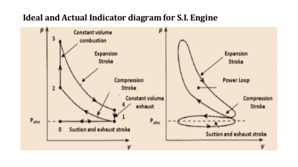
Process 0-1 (Suction stroke)
At the start of cycle the piston moves from TDC to BDC. The inlet valve (I.V.) is opened automatically by valve operating mechanism at the start of this process. Due to increase in volume inside the cylinder, a slight vacuum is created and, the fresh charge i.e. mixture of air and petrol prepared in Carburettor is sucked inside the cylinder through inlet valve. At the end of stroke, the piston reaches BDC position, total volume of cylinder is filled with fresh charge and inlet valve is closed. Theoretically, the charge is filled at constant pressure P1 and it occupies the total volume of cylinder V1.
Process 1-2 (Compression stroke)
During this stroke, both the valves remain closed and piston is moved from BDC to TDC by the force of crank. As the piston moves up, volume of cylinder shrinks and the fresh charge is compressed to a higher pressure P2 and volume V2 equal to clearance volume. Theoretically, this process is adiabatic compression process. Temperature of fresh charge is also raised in compression from T1 to T2.
Process 2-3 (heat addition or constant volume combustion)
This process is actually a constant volume heat addition process. At point 2, spark plug ignites and starts the combustion of already compressed, high temperature charge. Due to very favourable conditions of combustion, combustion of charge and heat release takes place in no time and pressure & temperature further shoots up to P3 and T3. Theoretically the volume remains constant from 2 to 3. So V2=V3=VC=Clearance Volume.
Process 3-4 (expansion or working stroke)
This is the process or stroke of piston in which positive work is obtained. The burnt gases at high pressure and high temperature at point 3 expand and push the piston again from TDC to BDC, thus doing work on the piston. This work is given to output shaft of engine through connecting rod and crank shaft. A small portion of it is stored in the heavy rotating flywheel mounted on crankshaft, which is used in movement of piston in three other idle stroke i.e. Suction, Compression and Exhaust. When piston reaches BDC, cylindrical total volume is filled with comparatively lower pressure and temperature burnt gases or smoke. At this point 4, the exhaust valve (EV) opens.
Process 4-1 (heat rejection or constant volume exhaust)
In this process, as soon as the exhaust valve is opened at point 4, the burnt gases start escaping to atmosphere and their pressure reduces to atmospheric pressure P1. Theoretically, this process happens in no time and escaping of exhaust gases take away some heat from the engine.
Process 1-0 (exhaust stroke)
This stroke is just opposite to suction stroke. Piston moves from BDC to TDC and pushes away or sweeps the remaining burnt gases out through E.V. As the piston reaches TDC most of burnt gases escape and E.V. Is closed. One cycle of the engine completes here. Simultaneously, the I.V. Opens and next cycle starts.
In this way, piston goes on moving or reciprocating from TDC to BDC and BDC to TDC with a high speed and engine produces power continuously by burning of petrol or gas etc. The power output and RPM of engine can be easily controlled by a throttling valve fitted in the passage of air intake or in the carburettor where fuel and air are mixed together in the right proportion In the exhaust phase, the piston goes upward and the burnt gases go away through the exhaust valve.
C.I Engine:
A diesel engine is called compression Ignition engine because here the conditions of combustion or ignition are achieved only by compression of air to a very high pressure.
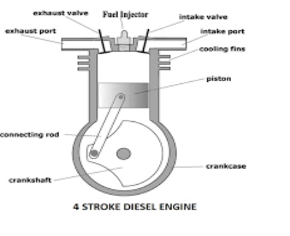
There is no spark plug to initiate the combustion, but in place of that a fuel injector is there, which injects and atomizes the fuel. Diesel at a very high pressure in very hot compressed air after compression stroke in engine Due to high pressure and temperature above the ignition temperature, fuel atomization, evaporation and self-ignition take place.
The rest of the working of Diesel Engine is same as that of Petrol or Gasoline Engine. Here also one complete cycle is comprised of all the processes of Diesel cycle along with suction of fresh air and exhaust of burnt gases. To carry out all these processes, here also normally 4 strokes of piston are required. So, it is called a 4-stroke Diesel Engine or C.I Engine.

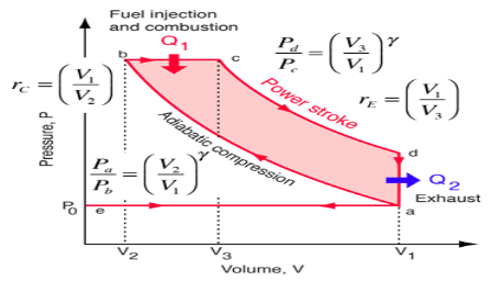
Process e-a (suction stroke)
At the start of cycle, the piston moves from TDC to BDC and inlet valve is opened at the start of process at point e. Due to increase in volume of cylinder by the movement of piston, the fresh air from atmosphere enters the cylinder and occupies all the space inside the cylinder until piston reaches BDC. At the point a, air filled in cylinder is at volume V1 and its pressure & temperature are theoretically same as that of outside atmosphere. Here inlet valve is closed and cylinder becomes a closed thermodynamic system.
Process a-b (compression stroke)
In this stroke, piston moves from BDC to TDC by the force of crank. As both valves are closed, the air sucked in previous stroke is compressed to the clearance volume. Here in Diesel engine the compression ratio rc which is the ratio of total volume V1 to clearance volume V2 is very high as compared to SI Engine. So, naturally the rise in pressure and temperature of air at the end of compression stroke is also more. The range of rc (compression ratio) in Diesel Engine is 15 to 22. Theoretically, the compression process is adiabatic & isentropic Compression.
Process b-c (heat addition or fuel injector)
This process is actually a constant pressure heat addition process or a mix of constant volume and constant pressure process as in case of high speed diesel engine. At the point b the fuel injector injects a fix quantity of fuel in very hot & compressed air compressed to the clearance volume. Due to that fuel spray ignites itself thus releasing of heat in the cylinder. As this heat addition process is slow, piston moves back to some distance from TDC to point c shown in fig and the volume increases which nullifies the effect of increase in pressure due to heat addition. Pressure remains constant theoretically upto point c, where the injector stops injection of fuel and so the addition of heat. Point c is also called cut-off point. A part of piston stroke from b to c takes place along with this process and the burning fuel plus air mixture expand and push the piston producing a positive work.
Process c-d (expansion stroke or power stroke)
Actually the complete expansion stroke is from point b to point d but a part of it is along the previous heat addition process b-c. After point c heat addition stops and the hot and high pressure burnt gases expand at the cost of their own internal energy and produce positive work by pushing the piston to BDC. This stroke is called working stroke as here piston moves the crankshaft and give mechanical energy. Major part of this energy is given to output shaft and a small portion is stored in heavy flywheel in the form of its rotational kinetic energy and used up during idle strokes of piston i.e. Suction, Compression & Exhaust.
Process d-a (heat rejection)
This process takes place at constant volume and heat is rejected directly by escaping of some of burnt gases due to pressure difference inside and outside the engine as soon as exhaust valve opens at point d i.e. just at the end of expansion or working stroke. Theoretically, piston remains at BDC and gases escape in no time, taking away some heat from the engine. Pressure inside the cylinder reduces to atmospheric pressure.
Process a-e (exhaust stroke)
In this process or stroke, piston is moved by crank from BDC to TDC. As the exhaust valve remains open during this stroke, piston displaces or sweeps out the burnt gases through it and only a small fraction of gases remain in the clearance volume finally. The piston reaches TDC and the cycle completes as the initial conditions are again reached. At this point, exhaust valve closes and inlet valve opens and next cycle starts.
In this way piston moves or reciprocates from TDC to BDC and again from BDC to TDC with a high speed and engine produces power continuously by burning of air and fuel mixture. The power output and RPM of engine here can be controlled by controlling the quantity of fuel injected only. There is no restriction on the quantity of air sucked by engine. There is a mechanical or electric control on the fuel injection depending on fuel injection system used. When more power is required more quantity of fuel is injected and when less power is required accordingly fuel supply is reduced. There is no control on the quantity of air so air sucked remains more or less same. In this way only the quality of combustible mixture changes in different conditions of loading and so Quality Governing is used in CI Engine.
Power Plant:
Types of Power plant
Nuclear power plants
Using a nuclear fission reaction and uranium as fuel, nuclear power plants generate high amount of electricity. As nuclear power plants emit low greenhouse gas emissions, the energy is considered environmentally friendly.
When compared to renewable sources of energy such as solar and wind, the power generation from nuclear power plants is also considered more reliable. Though the investments required to set up nuclear power plants are huge, the costs involved in operating them are low.
Nuclear energy sources also have higher density than fossil fuels and release massive amounts of energy Due to this, nuclear power plants require low quantities of fuel but produce enormous amounts of power, making them particularly efficient once up and running.
Hydroelectric power plants
Hydroelectricity is produced by harnessing the gravitational force of flowing water. Compared to fossil fuel-powered energy plants, hydroelectric power plants emit fewer greenhouse gases. However, the construction of hydroelectric power plants and dams requires huge investment.
According to the International Hydropower Association’s 2017 Hydropower Status Report, an estimated 31.5 GW of hydropower capacity was put into operation in 2016, bringing the world’s cumulative installed capacity to 1,246 GW.
China alone accounted for almost one third of global hydropower capacity and added around 11.74 GW of new capacity that year.
- Coal-fired power plants
According to World Coal Association, coal-fired power plants currently account for 41% of global electricity, with almost half of that coming from China alone. Coal-fired power plants use steam coal as source to generate electricity and consequently emit a significant amount of harmful gases into the atmosphere.
Diesel-fired power plants
With diesel as fuel, this type of power plant is used for small scale production of electric power. They are installed in places where there is no easy availability of alternative power sources and are mainly used as a backup for uninterrupted power supply whenever there are outages.
Diesel plants require only a small area to be installed and offer higher thermal efficiency compared to coal-fired power plants. Due to high maintenance costs and diesel prices, the power plants have not gained popularity at the same rate as other types of power generation plants such as steam and hydro.
- Geothermal power plants
The three main types of geothermal plants include dry steam power stations, flash steam power stations and binary cycle power stations, all of which use steam turbines to produce electricity.
As of May 2015, 24 countries were home to a combined geothermal power capacity of 12.8GW, according to a report by Geothermal Energy Association.
Geothermal power plants are considered environmentally friendly and emit lower levels of harmful gases compared with coal-fired power plants.
Combined-cycle power plants
Using both gas and steam turbines, combined-cycle power plants produce higher amounts of electricity from a single fuel source compared to a traditional power plant.
They capture heat from the gas turbine to increase power production and are also found to release low amounts of harmful gases into the atmosphere.
- Solar power plants
Solar energy plants convert energy from the sun into thermal or electrical energy using one of the cleanest and most abundant renewable energy sources. They generally do not require high maintenance and last for about 20-25 years.
The International Energy Agency (IEA) projected in 2014 that by 2050 solar photovoltaic and solar thermal would contribute about 16 and 11%, respectively, to the worldwide electricity consumption and solar would be the world’s largest source of electricity.
However, initial costs involved in setting up solar power plants are high and the installation of solar power systems requires a lot of space.
Solar thermal power plants
Solar thermal is a system of giant mirrors arranged in such a way so as to concentrate the sun’s rays on a very small area to create significant amount of heat, thus creating steam to power a turbine that creates electricity.
Wind power plants
In recent years, there has been a rapid growth in the number of wind farms across the world, underpinned by technological advancements. As wind is naturally occurring source of energy, there are no limitations to harness its power. Operational costs involved in maintaining wind power plants are low after the erection of wind turbines and they are generally considered cost effective. Wind farms can also be built on agricultural lands, without causing any interruption to cultivation activities.
However, maintenance of wind turbines may vary, as some need frequent check, and wind power projects typically require huge capital expenditure.
Tidal power plants
Tidal energy is generated from converting energy from the force tides into power and its production is considered more predictable compared to wind energy and solar power. Despite this, tidal power is still not exploited widely even as the world’s first large-scale tidal power plant became operational in 1966.
However, increased focus on generating power from renewable sources is expected to accelerate the development of new methods to exploit the tidal energy. Though the development of the tidal power is at the nascent stage, it is estimated to have vast potential globally.
In all power generating stations except solar power generating station employee alternator to generate electrical energy. An alternator is a rotating machine which can produce electricity only when it rotates. Hence there must be a prime mover which helps to turn the alternator. The primary arrangement of all power plants is to rotate the prime mover so that alternator can generate required electricity. In gas turbine power plant we use high pressure and temperature air instead of high pressure and temperature steam to rotate the turbine.
The fundamental working principle of a gas turbine power plant is same as that of a steam turbine power plant. The only difference is there that in steam turbine power plant we use compressed steam to rotate the turbine, but in gas turbine power plant we use compressed air to turn the turbine.
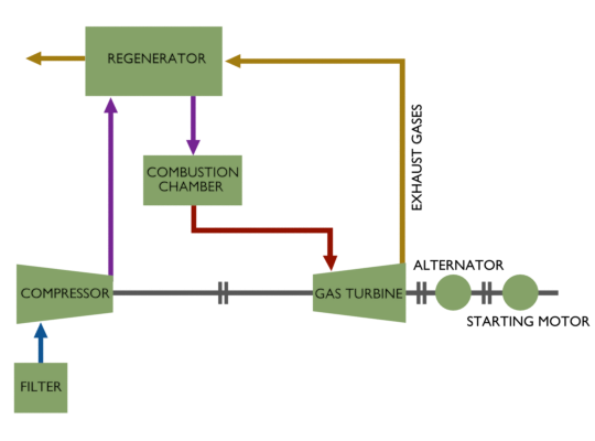
In the gas turbine power plant air is compressed in a compressor. This compressed air then passes through a combustion chamber where the temperature of the compressed air rises. That high temperature and high-pressure air is passed through a gas turbine. In turbine the compressed air is suddenly expanded; hence it gains kinetic energy, and because of this kinetic energy the air can do mechanical work for rotating the turbine.
In a gas turbine power plant, the shaft of turbine, alternator and air compressor are common. The mechanical energy created in the turbine is partly utilised to compress the air. Gas turbine power plants are mainly used as standby auxiliary power supplier in a hydroelectric power plant. It generates auxiliary power during starting of a hydroelectric power plant.
Advantages of Gas Turbine Power Plant
- Construction wise a gas turbine power plant is much simpler than a steam turbine power plant.
- The size of a gas turbine power plant is smaller than that of a steam turbine power plant.
- A gas turbine power plant does not have any boiler like component, and hence, the accessories associated with the boiler are absent here.
- It does not deal with steam hence it does not require any condenser hence no cooling tower like structure is needed here.
- As design and construction wise gas turbine power plants are much more straightforward and smaller, the capital cost and running cost are quite less than that of an equivalent steam turbine power plant.
- The constant loss is quite smaller in gas turbine power plant compared to a steam turbine power plant because in the steam turbine power plant boiler has to run continuously even when the system does not supply load to the grid.
- A gas turbine power plant can more instantly be started than an equivalent steam turbine power plant.
Disadvantages of Gas Turbine Power Plant
- The mechanical energy created in the turbine is also utilised to run the air compressor. Since a major portion of mechanical energy created in the turbine is utilised to run the air compressor the overall efficiency of gas turbine power plant is not as high as an equivalent steam turbine power plant.
- Not only have that, the exhaust gases in gas turbine power plant curries significant heat from the furnace. This also causes the efficiency of the system low further.
- To start power plant pre-compressed is required. So before actual starting of the turbine air should be pre-compressed which requires an auxiliary power supply for starting a gas turbine power plant. Once the plant is started there is no more need of supplying external power but at starting point external power is essential.
- The temperature of the furnace is quite high in a gas turbine power plant. This makes the system lifespan smaller than that of an equivalent steam turbine power plant.
- Because of its lower efficiency, a gas turbine power plant cannot be utilised for commercial production of electricity instead it is normally used to supply auxiliary power to other conventional power plants such as hydroelectric power plant.
Thermal energy is the major source of power generation in India. More than 60% of electric power is produced by steam plants in India. India has large deposit of coal (about 170 billion tonnes), 5th largest in world. Indian coals are classified as A-G grade coals.
In Steam power plants, the heat of combustion of fossil fuels is utilized by the boilers to raise steam at high pressure and temperature. The steam so produced is used in driving the steam turbines or sometimes steam engines couples to generators and thus in generating electrical energy.
Steam turbines or steam engines used in steam power plants not only act as prime movers but also as drives for auxiliary equipment, such as pumps, stokers fans etc. Steam power plants may be installed either to generate electrical energy only or generate electrical energy along with generation of steam for industrial purposes such as in paper mills, textile mills, sugar mills and refineries, chemical works, plastic manufacture, food manufacture etc.
The steam for process purposes is extracted from a certain section of turbine and the remaining steam is allowed to expand in the turbine. Alternatively the exhaust steam may be used for process purposes. Thermal stations can be private industrial plants and central station
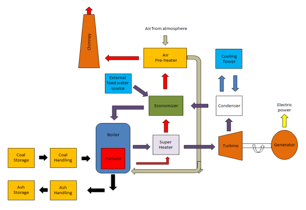
Components of Coal Fired Thermal Power Station:
Coal Preparation
i) Fuel preparation system:
In coal-fired power stations, the raw feed coal from the coal storage area is first crushed into small pieces and then conveyed to the coal feed hoppers at the boilers. The coal is next pulverized into a very fine powder, so that coal will undergo complete combustion during combustion process.
Pulverizer is a mechanical device for the grinding of many different types of materials. For example, they are used to pulverize coal for combustion in the steam-generating furnaces of fossil fuel power plants.
Types of Pulverisers: Ball and Tube mills; Ring and Ball mills; MPS; Ball mill; Demolition.
Ii) Dryers:
They are used in order to remove the excess moisture from coal mainly wetted during transport. As the presence of moisture will result in fall in efficiency due to incomplete combustion and also result in CO emission.
Iii) Magnetic separators:
Coal which is brought may contain iron particles. These iron particles may result in wear and tear. The iron particles may include bolts, nuts wire fish plates etc.
So these are unwanted and so are removed with the help of magnetic separators.
The coal we finally get after these above process are transferred to the storage site.
Purpose of fuel storage –
- Fuel storage is insurance from failure of normal operating supplies to arrive.
- Storage permits some choice of the date of purchase, allowing the purchaser to take advantage of seasonal market conditions. Storage of coal is primarily a matter of protection against the coal strikes, failure of the transportation system & general coal shortages.
There are two types of storage:
- Live Storage (boiler room storage): storage from which coal may be withdrawn to supply combustion equipment with little or no remanding is live storage. This storage consists of about 24 to 30 hours of coal requirements of the plant and is usually a covered storage in the plant near the boiler furnace. The live storage can be provided with bunkers & coal bins. Bunkers are enough capacity to store the requisite of coal. From bunkers coal is transferred to the boiler grates.
- Dead storage- stored for future use. Mainly it is for longer period of time, and it is also mandatory to keep a backup of fuel for specified amount of days depending on the reputation of the company and its connectivity. There are many forms of storage some of which are –
- Stacking the coal in heaps over available open ground areas.
- As in (I). But placed under cover or alternatively in bunkers.
- Allocating special areas & surrounding these with high reinforced concerted retaking walls.
Boiler and auxiliaries
A Boiler or steam generator essentially is a container into which water can be fed and steam can be taken out at desired pressure, temperature and flow. This calls for application of heat on the container. For that the boiler should have a facility to burn a fuel and release the heat. The functions of a boiler thus can be stated as:-
- To convert chemical energy of the fuel into heat energy
- To transfer this heat energy to water for evaporation as well to steam for superheating.
The basic components of Boiler are: -
- Furnace and Burners
- Steam and Superheating
a. Low temperature super heater
b. Platen super heater
c. Final super heater
Economiser
It is located below the LPSH in the boiler and above pre heater. It is there to improve the efficiency of boiler by extracting heat from flue gases to heat water and send it to boiler drum.
Advantages of Economiser include
1) Fuel economy: – used to save fuel and increase overall efficiency of boiler plant.
2) Reducing size of boiler: – as the feed water is preheated in the economiser and enter boiler tube at elevated temperature. The heat transfer area required for evaporation reduced considerably.
Air Preheater
The heat carried out with the flue gases coming out of economiser are further utilized for preheating the air before supplying to the combustion chamber. It is necessary equipment for supply of hot air for drying the coal in pulverized fuel systems to facilitate grinding and satisfactory combustion of fuel in the furnace.
Reheater
Power plant furnaces may have a reheater section containing tubes heated by hot flue gases outside the tubes. Exhaust steam from the high pressure turbine is rerouted to go inside the reheater tubes to pick up more energy to go drive intermediate or lower pressure turbines.
Steam turbines
Steam turbines have been used predominantly as prime mover in all thermal power stations. The steam turbines are mainly divided into two groups: -
- Impulse turbine
- Impulse-reaction turbine
The turbine generator consists of a series of steam turbines interconnected to each other and a generator on a common shaft. There is a high pressure turbine at one end, followed by an intermediate pressure turbine, two low pressure turbines, and the generator. The steam at high temperature (536 ‘c to 540 ‘c) and pressure (140 to 170 kg/cm2) is expanded in the turbine.
Condenser
The condenser condenses the steam from the exhaust of the turbine into liquid to allow it to be pumped. If the condenser can be made cooler, the pressure of the exhaust steam is reduced and efficiency of the cycle increases.
The functions of a condenser are:-
1) To provide lowest economic heat rejection temperature for steam.
2) To convert exhaust steam to water for reserve thus saving on feed water requirement.
3) To introduce make up water.
We normally use surface condenser although there is one direct contact condenser as well. In direct contact type exhaust steam is mixed with directly with D.M cooling water.
Boiler feed pump
Boiler feed pump is a multi-stage pump provided for pumping feed water to economiser. BFP is the biggest auxiliary equipment after Boiler and Turbine. It consumes about 4 to 5 % of total electricity generation.
Cooling tower
The cooling tower is a semi-enclosed device for evaporative cooling of water by contact with air. The hot water coming out from the condenser is fed to the tower on the top and allowed to tickle in form of thin sheets or drops. The air flows from bottom of the tower or perpendicular to the direction of water flow and then exhausts to the atmosphere after effective cooling.
The cooling towers are of four types: -
1. Natural Draft cooling tower
2. Forced Draft cooling tower
3. Induced Draft cooling tower
4. Balanced Draft cooling tower
Fan or draught system
In a boiler it is essential to supply a controlled amount of air to the furnace for effective combustion of fuel and to evacuate hot gases formed in the furnace through the various heat transfer area of the boiler. This can be done by using a chimney or mechanical device such as fans which acts as pump.
i) Natural draught
When the required flow of air and flue gas through a boiler can be obtained by the stack (chimney) alone, the system is called natural draught. When the gas within the stack is hot, its specific weight will be less than the cool air outside; therefore the unit pressure at the base of stack resulting from weight of the column of hot gas within the stack will be less than the column of extreme cool air. The difference in the pressure will cause a flow of gas through opening in base of stack. Also the chimney is form of nozzle, so the pressure at top is very small and gases flow from high pressure to low pressure at the top.
Ii) Mechanized draught
There are 3 types of mechanized draught systems
1) Forced draught system
2) Induced draught system
3) Balanced draught system
1) Forced draught: – In this system a fan called Forced draught fan is installed at the inlet of the boiler. This fan forces the atmospheric air through the boiler furnace and pushes out the hot gases from the furnace through super heater, reheater, economiser and air heater to stacks.
2) Induced draught: – Here a fan called ID fan is provided at the outlet of boiler, that is, just before the chimney. This fan sucks hot gases from the furnace through the superheaters, economiser, reheater and discharges gas into the chimney. This results in the furnace pressure lower than atmosphere and affects the flow of air from outside to the furnace.
3) Balanced draught:-In this system both FD fan and ID fan are provided. The FD fan is utilized to draw control quantity of air from atmosphere and force the same into furnace. The ID fan sucks the product of combustion from furnace and discharges into chimney. The point where draught is zero is called balancing point.
Ash handling system
The disposal of ash from a large capacity power station is of same importance as ash is produced in large quantities. Ash handling is a major problem.
i) Manual handling: While barrows are used for this. The ash is collected directly through the ash outlet door from the boiler into the container from manually.
Ii) Mechanical handling: Mechanical equipment is used for ash disposal, mainly bucket elevator, belt conveyer. Ash generated is 20% in the form of bottom ash and next 80% through flue gases, so called Fly ash and collected in ESP.
Iii) Electrostatic precipitator: From air preheater this flue gases (mixed with ash) goes to ESP. The precipitator has plate banks (A-F) which are insulated from each other between which the flue gases are made to pass. The dust particles are ionized and attracted by charged electrodes. The electrodes are maintained at 60KV.Hammering is done to the plates so that fly ash comes down and collect at the bottom. The fly ash is dry form is used in cement manufacture.
Generator
Generator or Alternator is the electrical end of a turbo-generator set. It is generally known as the piece of equipment that converts the mechanical energy of turbine into electricity. The generation of electricity is based on the principle of electromagnetic induction.
I) Sites selection criteria
The site of the thermal power plant is chosen with some specific conditions. The condition that must be fulfilled to build a thermal power is explained as below.
- Availability of Coal
A huge amount of coal is required for the generation of electrical energy. The thermal power station of 400 MW capacities requires 5000 to 6000 tons of coal per day. Therefore, thermal power stations should be located near to the coal mines to minimize the transportation cost.
- Ash Disposal Facilities
Ash produced after burning the coal is about 20 to 40% of the weight of the coal i.e. 1500 to 2000 tons per day. Thus, it becomes a more serious problem as it comes out in hot conditions and is highly corrosive. Therefore, there must be sufficient space available for the disposal of a large quantity of ash.
- Space Requirement
Space required for thermal power station is quite large for plant equipment, coal storage, ash disposal, staff colony, etc. The land available for the thermal power station must be available at low cost and with sufficient bearing capacity to withstand the load of machinery.
- Availability of Water
As the secondary requirement of the thermal power station is water.
The water is required for two purposes, firstly for conversation into steam for steam turbine and secondly for a condenser. Hence such power plants should be located near to the water resource such as river, lake, or canal.
- Transportation Facility
Power station should have the transportation facility such that as road and rail for transportation of material and machinery.
- Away from Populated Area
The thermal power station produces smoke and fumes by burning a huge amount of coal. This pollutes the atmosphere. Hence plants should be located at a considerable distance from the populated area.
- Near to the Load Center
Power stations should be located near to the load center to minimize the cost transmission system to transfer the electricity.
Environmental aspects for Site Selection of Thermal Power Plant
Air Pollution
Particulate meters SO2, NO2, and CO2 are emitted from the combustion of fuels in a thermal Power plant. If the uncontrolled, these affect humans, vegetation, buildings, and monuments, aquatic forest ecosystem.
The emission of large quantities of SO2 and NO2 from Thermal power plant may result in Acid-rain problems.
Waste Water Discharge
The large wastewater streams from Thermal power plant are cooling water below down, which can be either recycled or discharged to a surface water body, and then its chemical quality gets affected. Associated waste heat can impact ambient water temperature which in turn can radically alter aquatic plant and animal communities.
Other effluents from a Thermal power plant, like wastewater from de-mineralized backwash and resin regenerator wastewater, ash transport water and runoff from ash piles and sites, trace metals, acids and other chemicals in various combinations in the effluents, oil spills, etc. harm water quality.
Land Degradation
The thermal power stations are generally located on the non-forest land and do not involve much resettlement and rehabilitation problems.
However, its effects due to stack emission, etc. on flora and fauna, agricultural and other land have to be studied for any element percolation to groundwater through ash disposal in ash ponds are the serious effects of thermal power stations.
Noise Pollution
Some areas inside the plant will have noisy equipment such as crushers, belt conveyors, fans, pumps, milling plants, compressors, boiler, turbine, etc. Various measures to reduce the noise generation and exposure of workers to high noise levels in the plant area include silencers of fans, compressors, steam safety valves, etc., using noise absorbent materials, providing noise barriers for various areas, noise-proof control rooms.
II Advantage and disadvantage
Advantages The advantages of thermal power plants are listed below.
- The thermal power station has less initial cost as compared to the hydro-electric generating station.
- It requires less space as compared to the hydro power plant.
- The fuel cost is less as compared to a gas power plant.
- It can be installed at any location irrespective of coal mines. Coal can be transported to the site by road and rail.
- The huge amount of power can be generated by the thermal power station.
Disadvantages The disadvantages of thermal power plants are listed below.
- The running cost of the thermal power station is more as compared to the hydro generating station.
- It pollutes the atmosphere due to the production of a large amount of smoke and fumes.
- Maintenance cost is more.
- A skilled person is required for the Erection and Maintenance of the power station.
- Starting time is quite high (6 to 7 hours from the cold condition). Hence not suitable for peak loads.
- The overall efficiency of the thermal power station is very low (about 29%).
- Unavailability of good quality coal
- Maximum of heat energy lost
- Problem of ash removing
The heat energy in the nuclear power plant can be generated through a nuclear reaction or nuclear fission. The heavy elements of nuclear fission are Uranium/Thorium is carried out within a special device called a nuclear reactor. A huge amount of energy can be generated because of nuclear fission. The rest parts within the nuclear, as well as conventional thermal plants, are the same. The fission of 1 Kg Uranium generates heat energy which is equal to the energy generated through 4500 tons of high-grade coal. This significantly decreases the fuel transportation cost, so it is a major benefit of these plants. Worldwide, there are huge deposits of fuels existing; therefore, these plants can supply electrical energy continuously for hundreds of years. Nuclear power plants generate 10% of the electricity from the whole electricity in the world.
The power plant that is used to warm the water to generate steam, then this steam can be used for rotating huge turbines for generating electricity. These plants use the heat to warm the water which is generated by nuclear fission. So the atoms in the nuclear fission will split into different smaller atoms for generating energy.
Nuclear Power Plant Working Principle
In the power plant, the fission takes place in the reactor and the middle of the reactor is known as the core that includes uranium fuel, and this can be formed into pellets of ceramic. Every pellet generates 150 gallons of oil energy. The total energy generated from the pellets is stacked in metal fuel rods. A bunch of these rods is known as a fuel assembly and a reactor core includes several fuel assemblies.
During nuclear fission, the heat can be generated within the core of the reactor. This heat can be used to warm the water into steam so that turbine blades can be activated. Once the turbine blades activated then they drive the generators to make electricity. In a power plant, a cooling tower is available to cool the steam into the water otherwise they use the water from different resources. Finally, the cooled water can be reused to generate steam.
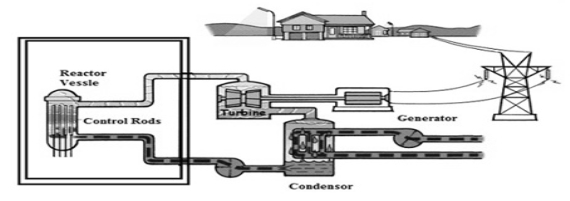
Components of Nuclear Power Plant
In the above nuclear power plant block diagram, there are different components which include the following.
1) Nuclear Reactor
In a power plant, a nuclear reactor is an essential component like a heat source that includes the fuel & its reaction of nuclear chain including the waste products of nuclear. The nuclear fuel used in the nuclear reactor is Uranium & its reactions are heat generated in a reactor. Then, this heat can be transferred to the coolant of the reactor to generate heat to all the parts in the power plant.
There are different types of nuclear reactors that are used in the manufacturing of plutonium, ships, satellites & aircraft for research as well as medical purposes. The power plant includes not only includes the reactor and also includes turbines, generators, cooling towers, a variety of safety systems.
2) Steam Generation
In all the power plants, the production of steam is general; however, the way of generating will change. Most of the plants use water reactors by using two loops of rotating water to generate steam. The primary loop carries very hot water for heating an exchange once water at a low-pressure is circulated, then it warms the water to generate the steam to transmit to the turbine section.
3) Generator & Turbine
Once the steam is generated, then it travels with high pressures to speed up the turbine. The rotating of the turbines can be used to rotate an electric generator for generating electricity that is transmitted to the electrical grid.
4) Cooling Towers
In a nuclear power plant, the most essential part is a cooling tower which is used to reduce the heat of the water. Please refer to this link to know more about what is a cooling tower – components, construction & applications
Working of Nuclear Power Plant
The elements like Uranium or Thorium are sued nuclear fission reaction of a nuclear reactor. Because of this fission, a huge amount of heat energy can be generated and it is transmitted to the coolant reactor. Here, the coolant is nothing but water, liquid metal otherwise gas. The water is heated to flow in a heat exchanger so that it changes into high-temperature steam. Then the steam which is produced is permitted to make a steam turbine run. Again the steam can be changed back into the coolant & recycled to use for the heat exchanger. So, the turbine and alternator are connected to produce electricity. By using a transformer, the electricity which is produced can be increased to use in long-distance communication.
I) PWR and BWR
Pressurized Water Reactor (PWR) | Boiling Water Reactor (BWR) |
Pressurized Water Reactor (PWR) power plants consist of two loops—(i) primary loop or coolant loop that takes away heat from reactor, and (ii) secondary loop or working fluid loop that drives the turbine. A heat exchanger (HE) is employed to transfer heat from primary loop to the secondary loop. | Boiling Water Reactor (BWR) power plants consist of a single loop where the coolant that takes away heat from the reactor is directly fed to the turbine. Thus no heat exchanger is desired. |
In the primary loop, normal water (H2O) acts as coolant-cum-moderator. In the secondary loop, the normal water acts as working fluid. However, water from one loop is not allowed to mix with the water of other loop. | Since it has only one loop, so normal water (H2O) serves all three purposes – cooling, moderation, and working fluid. |
Normal water in the primary loop that acts as moderator-cum-coolant is not allowed to boil. That means the water remains in liquid phase throughout the cycle of primary loop. However, the water in the secondary loop is allowed to boil. | Here the normal water (H2O) is allowed to change its phase. Thus the water (liquid phase) is first converted into steam (gaseous phase) within the reactor, and then the steam is again condensed to water before pumping back to reactor. |
Here steam is generated in a heat exchanger outside the nuclear reactor. | Here steam is generated within the reactor itself. |
Here the water in the primary loop is maintained at high pressure (15 – 17 MPa) to avoid boiling at reactor exit. | Here water pressure remains comparatively low (7 – 8 MPa) as it is allowed to boil. |
A pressurizer is required to use mandatorily to maintain water pressure in such a way that it does not evaporate even at very high temperature. | No such pressurizer is employed as evaporation of the water is desired. |
The temperature of the water at the reactor exit is kept around 310°C (corresponding to the working pressure to avoid boiling). | Steam temperature at reactor exit remains comparatively low (around 285°C). |
PWR has comparatively low thermal efficiency owing to two different loops. | BWR offers higher thermal efficiency. |
In PWR, the control rods are inserted from the top of the nuclear reactor. | In BWR, the control rods are inserted from the bottom of the nuclear reactor. |
Since the fluid is maintained at high pressure, so the PWR core volume is less. | For the same power generation, core volume of the BWR is comparatively larger. |
Since the working fluid loop is separated from the primary loop, so PWR is less risky in spreading of radioactive materials owing to leakage. | Since same fluid passes through the reactor and turbine in BWR plants, so any leakage in the turbine can spread radioactive elements into the atmosphere. |

II) Site Selection for Nuclear Power Plant
The selection of the site for nuclear PowerPoint can be done by considering the technical requirement. The arrangement and working of a nuclear power plant mainly depend on the characteristics of the site.
While designing the plant, the risks from the site must be considered. The plant design has to handle with tremendous natural occurrence & human-induced actions, without damaging the operational security of the plant.
Each site has to give needed necessities like discarded and decay heat sinks, power supply availability, excellent communications and efficient crisis management, etc. For a power plant, the estimate of the site typically occupies different stages like selection, characterization, pre-operational, and operational.
The purpose of characterisation of any particular area during the site selection stage is to determine the suitability of particular site for setting up a Nuclear Power Project (NPP). In this stage, geological, geo-morphological and geo-technical aspects are considered and regions or areas are usually identified that are excluded from further consideration. Subsurface information for this stage is usually obtained from current and historical documents, field reconnaissance, including geological surveys. In the recent past, remote sensing played great role in obtaining detailed and accurate information with minimum effort within least possible time frame. For a nuclear power plant, site evaluation typically involves the following stages,
a. Selection stage: One or more preferred candidate sites are selected after investigation of a large region, rejection of unsuitable sites, and screening and comparison of the remaining sites.
b. Characterization stage: This stage is further subdivided into:
• Verification-In which the suitability of the site to host a nuclear power plant is verified mainly according to predefined site exclusion criteria;
• Confirmation-In which the characteristics of the site necessary for the purposes of analysis and detailed design are determined.
c. Pre-operational stage: Studies and investigations from the previous stages are continued to refine the assessment of site characteristics. Data obtained from site allow a final assessment of simulation models used in the ultimate design of foundation and superstructure as well.
d. Operational stage: Selected investigations are pursued over the lifetime of the plant, to ensure that the variation of engineering properties are not varying significantly during the operating life of the plan
III) Advantages and disadvantages
Advantages
The advantages of nuclear power plants include the following.
1) It uses less space compared with other power plants
2) It is extremely economical and generates huge electric power.
3) These plants are located near the load center because there is no requirement of huge fuel.
4) It generates a huge amount of power in the process of each nuclear fission
5) It uses less fuel to generate huge energy
6) Its operation is reliable
7) When compared with steam power plants, it is very clean and neat
8) The operating cost is small
9) It doesn’t produce polluting gases
Disadvantages
The disadvantages of nuclear power plants include the following.
1) The cost of primary installation is extremely high when compared with other power stations.
2) The nuclear fuel is expensive so recovering is difficult
3) High capital cost compare with other power plants
4) Technical knowledge is required to operate this plat. So maintenance, as well as salary, will be high.
5) There is a chance of radioactive pollution
6) The response is not efficient
7) The requirement of cooling water is double compare with a steam power plant.
Applications
The applications of nuclear power plants include the following.
Nuclear energy is used in different industries all over the world for desalination of ocean water, production of hydrogen, district cooling/heating, the removal of tertiary oil resources & used in heat process applications like cogeneration, conversion of coal to liquids & help in the chemical feedstock synthesis.
Automobile engineering is the field of study which deals with designing, repairing and manufacturing, operating and developing automobiles. An automobile engineer deals in all these areas and applies this knowledge in designing engines and production of cars as it is one of the main areas of specialization in automobile engineering.
There are various other programs available in this area which the aspirants learn throughout the automobile engineering course. Some of them include aerodynamics, electronics, fluid mechanics, thermodynamics, fuel emissions, safety engineering, control systems, motorsport and supply chain management.
Automobile engineering provides various areas of expertise and learning in the field of automobiles and electronics for those who are enthusiastic about cars and vehicles and their functioning.
Ever since motor vehicles came to be, automobile (also known as automotive or vehicle) engineering has gained importance. Automobile engineering deals with the design and creation of vehicles used as means of transportation by road. Essentially, it derived from mechanical engineering. More specifically, it is the branch of engineering that deals with the design, development, manufacturing, production, testing, repairing, control and management of automobiles. It is a combination of different elements of mechanical engineering, electrical engineering, electronic engineering, software engineering and safety engineering.
The main areas of application are in car design, operations involving the production of cars, designing of engines and fuel management. To become a capable and skilled automobile engineer, specialized training may be essential.
The major tasks of an automobile engineer are to design, develop, manufacture and test vehicles from the conceptual phase to production phase. It has many areas of specialization such as engine systems, fluid mechanics, aerodynamics, supply chain management, thermodynamics and electronics and control systems.
An understanding of the internal combustion engine, the mechanism of the vehicle chassis, electrical systems, workshop technology, motor transport affairs, and research and design is important.
Automotive engineers can work within a range of roles in the manufacture of cars, motorcycles, vans and other commercial vehicles: design, manufacture, distribution, marketing, sales and after-sales care. While most automotive engineers are employed by vehicle manufacturers, other employers include tyre manufacturers, specialist vehicle design companies and research/test laboratories, motor sports teams and oil/fuel companies. Self-employment via consultancy and contract work can also be an option, though several years of relevant experience may be necessary.