UNIT 5
Basic mechanical engineering
Whether you’re creating a component from scratch, or modifying widely used technology, it is important to understand the basics of mechanical design. To design and produce an effective part, engineers must take into account all aspects of form and function to ensure that their product will not only operate as expected, but be able to be manufactured in the first place.
Understanding Stress/Force
In what kind of environment will your part live? Under what stresses will it routinely be placed? There are many factors that can help or hinder a parts performance (temperature, moisture, dust/debris, impact, range of motion, etc.) When it comes to mechanical design, the more research an engineer can do up front the better. A machine element that works great in the snow could fail in the desert, and these varying conditions will need to be accounted for.
Know your Materials
With a keen understanding of the stresses at play in a particular environment, the next decision in the machine design process is what material to use in manufacturing a part. Certain metals are more resistant to corrosion and warping. Different plastics hold up better to heat and friction. If weight is a factor, there a number of high-strength light-weight materials available, but they come at a cost. These are all factors to keep in mind throughout the machine design process.
Understand the Technology
Before a part is completely designed, it is important to have a firm understanding of the manufacturing technology at one’s disposal to ensure that a part can be produced effectively and affordably. Mechanical engineers will often work closely with their machine shop to discuss challenges or limitations in their design elements, and to brainstorm potential areas of improvement (machine availability, required tolerances, bend geometry, etc.) The most mind-blowing design in the world could look great in a CAD model, but if it doesn’t do a lot of good if it can’t actually be machined.
Machine design is basically classified into three basic parameters I.e. Machine drawing, Machine design and Application of design on actual system.
In basics following Topics are used to discuss.
1) knowledge of Material and its Properties
2) Introduction of Stresses and Strain.
3) Introduction of various types of Loading conditions and its effect.
4) Various Principle, Laws to govern Static and dynamic loading conditions.
5) Various methods, approach of implementation for solving any Problem.
After detail study of this design basics, next step is to implement this knowledge for designing small Machine parts and Assembly which all together helps to understand applications of design on actual machineries and industries.
MACHINE- A machine is an arrangement of part for doing work, for applying power or changing its direction.
MECHANICS- It is the branch of science that deals with motions, time and forces. It consists of two parts, statics and dynamics.
- Statics deals with analysis of stationary system where time is not a factor.
- Dynamics deals with the analysis of systems that change with time. It has two branches called kinematics and kinetics.
- Kinematics deals with the study of motion or it is the study of position, displacement, rotation, speed, velocity and acceleration.
- Kinetics deals with forces acting in the system.
KINEMATIC LINK- kinematics link is a resistant body or an assembly of resistant bodies that make a part or parts of machines connecting other parts having motion relative to it.
STRUCTURE- it is an assembly of resistant bodies that have no relative motion between them. Example- roof trusses, bridges etc.
Difference between a Machine & a Structure
MACHINE | STRUCTURE |
|
|
|
|
|
|
KINEMATIC PAIR- It is a joint of two links that permits relative motion. Example- slider cranks mechanism.
TYPES OF KINETIC PAIRS
1) Sliding pair- when the two elements of a pair are connected in such a way that one element can slide relative to the other. Example- the piston and cylinder, tail stock on lathe bed.
2) Turning pair- when the two elements of a pair are connected in such a way that one element can revolve about a fixed axis of another link. Example- lathe spindle supported on head stock.
3) Rolling pair- when the two elements of a pair are connected in such a way that one can roll over another fixed link. Example-ball and roller bearings.
4) Screw pair- when the two elements of a pair are connected in such a way that one element can turn about the other by screw threads. Example-nut and bolt.
5) Spherical pair- when the two elements of a pair are connected in such a way that one element can turn about the other fixed element. Example- ball socket joint.
6) Lower pair- when the two elements of a pair have surface contact when relative motion takes place and the surface of one element slides over the surface of the other element. Example- sliding, turning and screw pairs.
7) Higher pair- when the two elements of a pair have a line or point contact when relative motion takes palace and the motion between the two elements is partly turning and partly sliding. Example- toothed gearing.
TYPES OF CONSTRAINED MOTIONS-
1) Completely Constrained Motion- when the motion between a pair is limited to a definite direction irrespective of the direction of force applied. Example- the motion of a square bar in a square hole.
2) Incompletely Constrained Motion- when the motion between a pair can take place in more than one direction. Example- a circular bar in a circular hole where the bar can either rotate or slide in the hole.
3) Successfully constrained motion- when the motion between a pair is such that the constrained motion is not completed by itself but by some other means. Example- piston reciprocating inside an engine cylinder.
KINEMATIC CHAIN-
It is defined as a combination of kinematic pairs joined in such a way that each link forms a part of two pairs and relative motion between the links is completely or successfully constrained. When any one link is fixed then the kinematic chain becomes a mechanism.
Relation between no. Of pairs (p) and no. Of links (l)
l= 2p – 4
Relation between no. Of links (l) and no. Of joints (j)
j = 3/2 l – 2
Klein’s formula,
j + h/2 = 3/2 l – 2
When L.H.S > R.H.S, then the chain is locked.
When L.H.S < R.H.S, then the chain is unconstrained chain.
When L.H.S = R.H.S, then the chain is a kinematic chain.
MECHANISM-
When one of the links of a kinematic chain is fixed then the chain is called a mechanism. It transmits and modifies motion. The process of obtaining different mechanisms by fixing different links in a kinematic chain is known as inversion of the mechanism.
KINEMATIC CHAINS AND THEIR MECHANISMS-
- Four bar chain or quadric cycle chain- It consists of four links and each of them forms a turning pair. The inversions of four bar chain mechanism,
- Crank and lever mechanism (oscillatory motion) – Here the crank is able to rotate completely but the follower can only give an oscillatory motion. Example- beam engine.
- Double crank mechanism- Here in this inversion there is a complete rotation of the crank and the follower. Example- coupling rod of a locomotive.
Double lever mechanism- example- watt’s indicator mechanism, pantograph.
- Slider crank mechanism- It consists of three turning pairs and one sliding pair. It converts rotary motion into reciprocating motion and is found in reciprocating steam engines. The inversions of slider crank mechanism,
1st inversion- Example- Internal combustion engine, pump, reciprocating steam engine.
2nd inversion- It is obtained by keeping the connecting rod fixed. It is called as crank and slotted lever mechanism. Example- oscillating cylinder engine.
3rd inversion- It is obtained by keeping the crank fixed. Example- Whitworth quick return motion mechanism. This mechanism is used in shapers.
- Double slider crank chain mechanism- It consists of two sliding pairs and two turning pairs. The inversion of double slider crank chain mechanism,
- Elliptical trammels
- Scotch yoke mechanism
- Oldham’s coupling
Machine is devise or tool, which transfers the power from one point to other point. If you feed the power in point, it gives the power where you want the power. So crow bar, leaver, chain and pully, a rod, a hammer, a wheel all is machines. Rope and pulley, a door, a knife all are machines. It is not essential a should have links to become a machine. Purpose is power transmitting or power point is shifting.
When the purpose of shifting, is failed, by available means and items, them like to be added to shift the power. So a bicycle pedal and the last wheel. So link should be very minimum, to increase mechanical advantage. Otherwise the mass of items eats the power, in terms of mass and friction, and air friction etc. so lubrication is required to cure the frictions. Air friction and mass momentum friction cannot be stopped. So minimum linkage is necessary to create a efficient machine.
Whatever you do may, power will be consumed in between, and output never will be 100%. So mechanical advantage is always less than one.
So last power is called sacrifices.
Levers principle is used in automotive gears, lathe, turning and drilling machines. This gear helps in increasing the speed and reducing the tongue. So lever etc. do not add additional power to the system, but reducing the speed, increases the torque, in high elevated driving or hills.
Seeing the power of levers, the great Archimedes, called the world “Give a space, other than earth I can shift the earth where you want”. Hence machines are beautiful, in for doing in our regular life, fish catching, animals and birds catching, etc.,
This systems binary based which is called computers, mobile phones, etc., also machines, and called digital machines. Next the creation is also called machine, where mantra is knowledge, and creation is called as Brahmana or yantra.
Factor of safety (FoS) is ability of a system's structural capacity to be viable beyond its expected or actual loads. An FoS may be expressed as a ratio that compares absolute strength to actual applied load, or it may be expressed as a constant value that a structure must meet or exceed according to law, specification, contract or standard.
Design and engineering standards usually specify the allowable stress, or ultimate strength of a given material divided by the factor of safety, rather than use an arbitrary safety factor, because these factors can be misleading and have been known to imply greater safety than is the case. For example, a safety factor of 2 does not mean that a structure can carry twice as much load as it was designed for.
The safety factor depends on the materials and use of an item. Different industries have varying ideas on what FoS should be required. Although there is some ambiguity regarding safety factors, there are some general guidelines across multiple verticals. If the consequences of failure are significant, such as loss of life, personal harm or property loss, a higher FoS is likely to be required by design or by law. When a structure’s ability to carry load must be determined to a reasonable accuracy but comprehensive testing is impractical (such as with bridges and buildings), safety factors need to be calculated using detailed analysis.
Cost is also a consideration. As the FoS increases, the cost of the product also increases, so it may be necessary to determine how much extra it might cost per part to achieve a certain FoS, and whether that is a viable business model. Striking a balance between cost reduction and safety is essential.
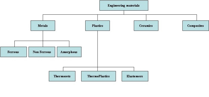
Engineering Materials:
. Classification of Engineering Materials
2. Properties of Engineering Materials
PHYSICAL PROPERTIES
- Specific Gravity-defined as the weight of a given volume of a material as compared to the weight of an given volume of water it is measured at a temperature of 60 degree F(15.5 degree C)
- Specific Heat-heat required to raise the temperature of unit weight of material by one degree.
- Fusibility & Fluidity-the property of a material where it tends to melt and flows when heat is applied.
- Weld ability-ability of uniting two pieces of metal by applying pressure or heat or both.
- Elasticity-property due to which a metal regains its original dimension on removal of load.
- Plasticity-beyond elastic limit the material is unable to regain its original shape and retains to its moulded shape. This property is called plasticity.
- Porosity-materials in their plastic or molten state contain some dissolved gasses which are evaporated once they are set forming as holes and pores .this property is known as porosity.
MECHANICAL PROPERTIES
- Strength-ability of a material to resist the application of load without rupture.
- Hardness-ability of a material to resist penetration or scratching.
- Hardenability-ability of a material to be hardened by heat treatment.
- Toughness-property of a material where it can absorb energy before actual fracture.
- Brittleness-ability of a material to fracture on receiving shock or blow
- Malleability-ability of a material to be hammered into thin sheets.
- Ductility-ability of a material to be drawn into wires.
- Creep & Slip-ability of a material to flow like a viscous liquid under the application of stress and temperature is called creep .the phenomenon where deformation stops even if the load is acting.
- Resilience-property of a material to absorb energy within elastic range. This required for springing action.
THERMAL PROPERTIES
- Conductivity-ability of a material to conduct heat from a hot end to cold end. Silver and copper are good conductors of heat.
ELECTRICAL PROPERTIES-
- Conductivity-ability of a material to conduct electricity from one end to another.
MAGNETIC PROPERTIES
- Ability of material to act as a magnet and attract materials like iron, steel, nickel etc.
In mechanics, the need to join pieces like plates, sections, and bars is very common. Any assembly, however simple it may be, requires the union of parts together, but the mechanical parts to be joined require the proper elements of marriage that are named fasteners.
Most commonly, the fasteners used in mechanics are: rivets, pins, bolts, screws, nuts, washers, and braces.
Mobile and permanent fasteners
The union of parts made by the fasteners can be of two types: mobile or permanent.
In the mobile type of union, the fasteners can be placed or removed from the set without causing any damage to parts that were attached. This is the case, for example, unions made with bolts, nuts and washers.
The type of permanent union, the fasteners, when installed, can not be removed without becoming unusable. This is the case, for example, for unions made with rivets and welds.
Both mobile and permanent bonding should be used with great skill and care because they are usually the weakest components of the machine. Thus, to design a mechanical assembly, it is necessary to choose the fixture for the type of parts that will be attached or fixed. If, for example, if you join robust parts with weak and poorly planned fasteners, the assembly will present failures and may become unusable, occasioning waste of time, material, and financial resources.
It is still important to plan properly and choose the correct fasteners to be used to avoid stress concentration in the parts set. These strains can cause disruption due to fatigue of the material, ie, the decrease of strength or weakness of the material due to stress and constant effort.
Kinds of fasteners
- A screw is a piece consisting of a cylindrical body and a screw head, which can take many forms;
- The nut is shaped like a prism or cylinder and presents a threaded hole. Through this hole, the nut is screwed to the screw;
- The rivet is formed by a cylindrical body and a head. It is manufactured in steel, aluminum, copper or brass. It is used for permanent fixed-tion of two or more pieces;
- Pins join articulated parts. In this type of union, one of the pieces can move by rotation;
- The peg connect parts that are not interconnected;
- The cotter is a rod or wire in a shape similar to that of a half-cylinder, folded so as to make a circular head and has two uneven legs. Place the counter-pin or cotter pins in a hole at the end of a pin or screw and nut castle. Cotter’s legs are turned backwards and thus prevent the output of the pin or nut during vibrations of the clamped parts;
- The washer is a metal disk with a hole in the center and the body of the screw goes through the hole;
- The snap ring is used to prevent displacement of axes. It also serves to position or limit the movement of a piece that slides over a shaft
Machinability
Machinability is defined as the ease with which a material can be machined to intended geometry and purpose at a satisfactory cost. The machinability often regarded as the work piece material property, however, the ease of machining also depends on other factors such as rigidity of cutting tool. Good machinability related to removal of material with moderate forces, good surface finish, small chips, and with minimum tool wear. It is difficult to maintain all these objectives at once for a machining operation. For example, the fine-grained material results in good surface finish but have high resistance to machining. So it is always a challenge to engineers to find ways to improve machinability without spoiling the performance.
Factors that affect machinability
It is difficult to predict machinability because of various factors affecting machinability. The machinability depends on the following machining process parameters, conditions and physical properties of workpiece.
Material variables:
- Microstructure and grain size of workpiece
- Heat treatment of material
- Chemical composition of workpiece such as presence of alloying metal.
- Hardness, tensile strength and ductility of workpiece
Machining variables:
- Rigidity of tool, fixture, and work holding devices.
- Tool geometry, tool dullness etc. indirectly affects the machinability.
- Cutting parameters such as feed, speed, cutting force etc. are directly affect machinability.
- Use of cutting fluid.
Generally, hardness decreases machinability because of high power consumption, high temperature and high tool wear. The coarse-grained steel shows better machinability than fine grained steel because fine grain will have better strength and hardness. Presence of alloying materials has much greater effect on the machinability than the effect of hardness on machinability. The small amount of alloying metal (less than 0.2%) of Sulphur S and lead Pb can improve machinability without having a noticeable change in mechanical properties. Heat resisting steels and super alloys are generally shown poor machinability. Poor thermal conductivity causes heat build-up at cutting zone, which eventually degrades the tool life. One of the major factor to be considered during machining is the condition of tool. The dull cutting tools drive at too small feed may fail to cut chips and cause work hardening of material surface.
Machinability index
Advantages of machinability
- Result of good machinability are listed below
- High cutting speed can be used.
- High material removal rate
- Low power consumption.
- Tool wear rate is very low and good tool life.
- Good surface finish
- Minimum idle time.
Lathe Machine is the most widely used lathe machine and still, it is, in every workshop, this machine is present. The operation like Turning, facing, grooving, Knurling, threading and more, such operations are performed on this type of machine.
Centre lathe machine has all the parts such as bed, Saddle, headstock, and tailstock, etc. The headstock of an engine lathe is rigid and tailstock is moveable which is further used to support an operation like knurling. It can easily feed the cutting tool in both directions i.e. longitudinal and lateral directions with the help of feed mechanisms. Center Lathe machines are driven by the gear mechanism or pulley mechanism. It has three types of driven mechanisms, and those are Belt-driven, Motor-driven, gear head type.
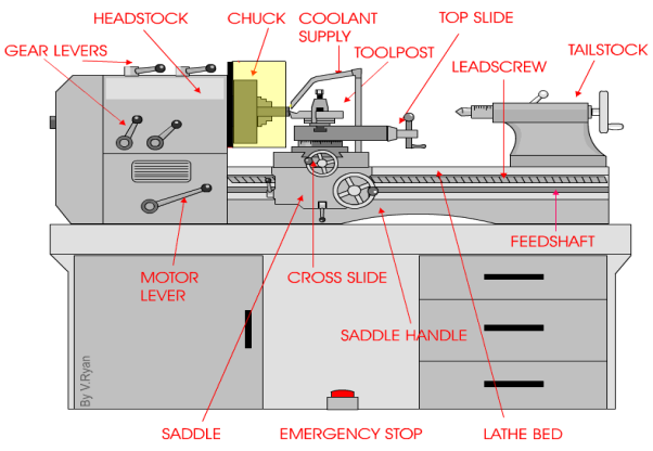
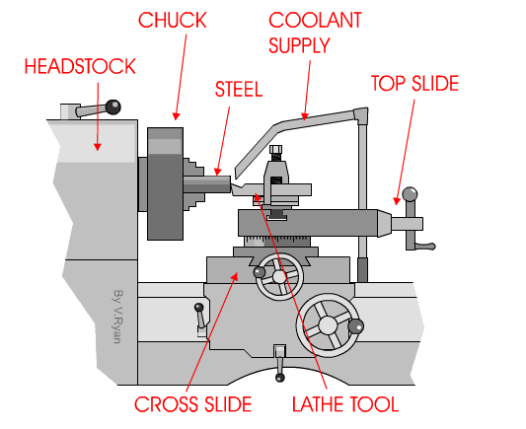
The Centre Lathe is used to manufacture cylindrical shapes from a range of materials including; steels and plastics. Many of the components that go together to make an engine work have been manufactured using lathes. These may be lathes operated directly by people (manual lathes) or computer controlled lathes (CNC machines) that have been programmed to carry out a particular task. A basic manual centre lathe is shown below. This type of lathe is controlled by a person turning the various handles on the top slide and cross slide in order to make a product / part.
The headstock of a centre lathe can be opened, revealing an arrangement of gears. These gears are sometimes replaced to alter the speed of rotation of the chuck. The lathe must be switched off before opening, although the motor should automatically cut off if the door is opened while the machine is running (a safety feature).
The speed of rotation of the chuck is usually set by using the gear levers. These are usually on top of the headstock or along the front and allow for a wide range of speeds.
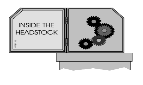
However, sometimes the only way to set the lathe to a particular speed is to change the gear arrangement inside the headstock. Most machines will have a number of alterative gear wheels for this purpose.
i) Basic element:
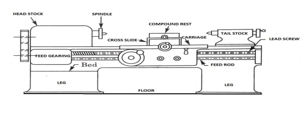
A lathe machine tool consists of several parts like:
- Headstock
- Bed
- Tailstock
- Carriage
- Saddle
- Cross-slide
- Compound rest
- Tool post
- Apron
- Lead Screw
- Feed rod
- Chuck
- Main spindle
- Leg
1) Head Stock:
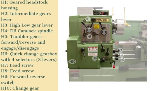
Head Stock is situated at the left side of the lathe bed and it is the house of the driving mechanism and electrical mechanism of a Lathe machine tool.
- It holds the job on its spindle nose having external screw threads and internally Morse taper for holding lathe center. And it is rotating at a different speed by cone pulley or all geared drive. There is a hole throughout spindle for handling long bar work.
- Head Stock transmits power from the spindle to the feed rod, lead screw and thread cutting mechanism.
Accessories mounted on headstock spindle:
- Three jaw chuck
- Four jaw chuck
- Lathe center and lathe dog
- Collect chuck
- Faceplate
- Magnetic chuck
A separate speed change gearbox is placed below headstock to reduce the speed in order to have different feed rates for threading and automatic lateral movement of the carriage. The feed rod is used for most turning operation and the lead screw is used for thread cutting operation.
2) Bed:
It is the base of the lathe machine. It is made of single piece casting of Semi-steel (Chilled Cast Iron). The bed consists of two heavy metal slides running lengthwise, with ways or ‘V’ formed upon them and rigidly supported with cross girths.
- It is sufficiently rigid and good damping capacity to absorb vibration.
- It prevents the deflection produced by the cutting forces.
- It supports the headstock, tailstock, carriage and other components of the lathe machine.
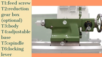
3) Tail Stock:
Tail Stock is situated on the right side above the lathe bed. It is used for:
- Support the long end of the job for holding and minimizes its sagging.
- It holds the tool for performing different operations like drilling, reaming, tapping, etc.
- And it is also used for a small amount of taper for a long job by offsetting the tailstock.
4) Carriage:
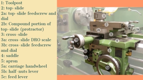
The carriage is used for support, guide and feed the tool against the job when the machining is done.
- It holds moves and controls the cutting tool.
- It gives rigid supports to the tool during operations.
- It transfers power from feed rod to cutting tool through apron mechanism for longitudinal cross-feeding.
- It simplifies the thread cutting operation with the help of lead screw and half nut mechanism.
It is consists of:
- Saddle
- Cross-slide
- Compound rest
- Tool post
- Apron
It provides three movements to the tool:
- Longitudinal feed-through carriage movement
- Cross feed-through cross slide movement
- Angular feed-through top slide movement
5) Saddle:
Generally, it is made up of ‘H’ shaped casting and it has a ‘V’ guide and a flat guide for mounting it on the lathe bed guide ways.
6) Cross-slide:
It is assembled on the top of the saddle. The top surface of the cross-slide is provided with T-slot.
7) Compound rest:
It supports the tool post and cutting tool in its various positions. It can be swiveled at any desired position in the horizontal plane. It is necessary for turning angles and boring short tapers.
8) Tool post:
It is the topmost portion of the carriage and it is used to hold various cutting tools or tool holders. There are three types of tool post commonly used and those are:
- Ring and rocker tool post
- Square head tool post
- Quick change tool post
9) Apron:
An apron is a house of the feed mechanism. It is fastened to the saddle and hangover in front of the bed.
10) Lead screw:
A lead screw is also known as a power screw or a translation screw. It converts rotational motion to linear motion. Lead Screw is used for Thread Cutting operation in a lathe machine tool.
11) Feed Rod:
Feed rod is used to move the carriage from the left side to the right side and also from the right side to the left side.
12) Chuck:
Chuck is used to holding the work piece securely.
There are generally 2 types of chucks:
- 3 jaw self-cantering chuck
- 4 jaw independent chuck
13) Main Spindle:
The spindle is a hollow cylindrical shaft in which long jobs can pass through it.
It is designed so well that the thrust of the cutting tool does not deflect the spindle.
14) Leg:
Legs are carrying an entire load of a lathe machine tool and transfer to the ground. The legs are firmly secured to the floor by the foundation bolt.
Ii) Working operation on lathe:
A Lathe Machine consists of the following operation:
1) Centering
2) Facing
3) Turning
4) Chamfering
5) Knurling
6) Thread cutting
7) Drilling
8) Boring
9) Reaming
10) Spinning
11) Tapping
12) Parting off
Before continuing any operation in lathe we have to load the job and center it on the head-stock spindle.
In lathe operations, the headstock spindle holds the job and it rotates with the same speed as the spindle. The carriage holding the tool on the tool post, also the carriage gives the tool post moves longitudinally or crosswise direction to give the desired feed on the job.
These two motions (longitudinally and crosswise) help to remove the chips of the metal and giving the proper shape of the job. The Lathe is such a versatile machine that it can produce another lathe. It is tough to mention which operations are not performed in a lathe machine tool, though we discuss some important lathe operations in detail.
1) Centering operation in the lathe:
We use this operation for producing a conical hole in the face of the job to make the bearing support of the lathe center when the job is to hold between two canters. (Head-stock and Tail-stock)
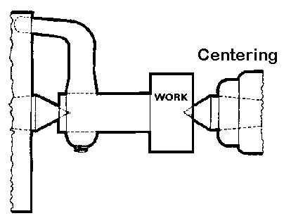 CENTERING OPERATION
2) Facing operation in the lathe:
Facing operation is for making the ends of the job to produce a smooth flat surface with the axis of operation or a certain length of a job. In this operation,
- Hold the job on Head-stock spindle using Three or four-jaw chuck.
- Start the machine on desire RPM to rotate the job.
- Give a desirable feed on the perpendicular direction of the axis of the job.
![22 Types of Lathe Machine Operations [Complete Guide] PDF](https://glossaread-contain.s3.ap-south-1.amazonaws.com/epub/1643293327_5611875.jpeg)
3) Turning operation in the lathe:
The operation by which we remove the excess material from the work piece to produce a cone shaped or a cylindrical surface
There are several types of turning operations, those are:
- Straight turning
- Shoulder turning
- Rough turning
- Finish turning
- Taper turning
- Eccentric turning
Straight turning:
This operation is done to produce a cylindrical surface by removing excess material from the work piece.
It is done in the following ways:
- Mount the job by suitable job holding device and check the trueness of the job axis with the lathe axis.
- Hold the cutting tool on the tool post and set the cutting edge at the job axis or slightly above it.
- Set the spindle as per the desired feed.
- Give depth of cut as per finish or rough cut.
- Start the machining.
- Engage automatic feed to move the carriage with the tool to the desired length, then disengage the feed and carriage is brought back to its starting.
- The process is repeated until the job finished.
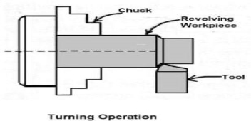
STRAIGHT TURNING OPERATION
Shoulder turning:
A shoulder turning is called which has a different diameter to form a step from one diameter to another. There are four kinds of the shoulder.
- Square
- Bevelled
- Radius
- Undercut
![22 Types of Lathe Machine Operations [Complete Guide] PDF](https://glossaread-contain.s3.ap-south-1.amazonaws.com/epub/1643293327_7051003.jpeg)
Rough turning:
It is a process of removal of excess material from the work piece in minimum time by applying a high rate of feed and heavy depth of cut.the depth of cut is around 2 to 5mm and the rate of feed is 0.3 to 1.5mm/revolution.
Finish turning:
The finish turning operation needs high cutting speed, minimum feed and a very small depth of cut to generate the smooth surface.
In finish turning the depth of cut is around 0.5 to 1mm and the rate of feed is 0.1 to 0.3 mm/revolution.
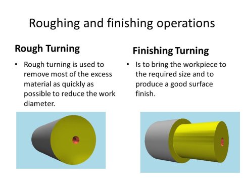
Taper turning:
A taper is defined as a uniform decrease or increase in the diameter of a work piece along with its length.
The operation by which a conical surface of the gradual reduction in diameter from a cylindrical work piece is produced is called taper turning.
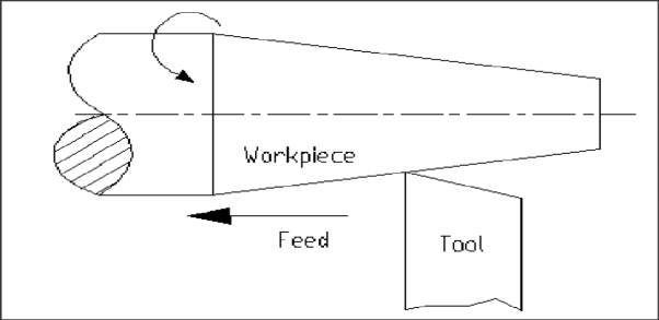
Taper turning methods:
A tapering form may be done by anyone of the following methods.
- Taper turning by form tool
- By swivelling the compound rest
- Tail-stock set over method
- By taper turning attachment
Let me discuss them in brief.
Taper turning by form tool:
It is used to form a short length of taper by using a form tool or broad nose tool.
Any increase in the length of taper will require the use of a wider cutting edge which may destroy the work piece due to the vibration and spoil the work piece. In this operation, the tool angle must be half of the taper angle.
Taper turning by swiveling the compound rest:
This method is used for turning step and short tapers.
It is done as follows:
- Set the compound rest by swiveling it from the centerline of the lathe center through an angle equal to a half taper angle.
- Clamp the carriage in place.
- After adjusting and setting the tool, feed is applied by the compound rest’s feed handle to complete the taper.
Tail-stock set over method:
Set over of tail-stock from its center-line is done equal to half taper.
Job is held between the centers. The length of the workpiece will be long enough. An only a small taper on a long job is done by this process.
It is used for external taper only.
By taper turning attachment:
It is done in the following ways:
- The cross slide is first made free from lead screw by hinder screw.
- The rear end of the cross slide is then tightened with a guide block by a belt.
- Set the guide bar at an angle to the lathe axis. (Half taper angle)
- The required depth of cut is given by the compound slide is at a right angle to the lathe axis.
4) Chamfering operation:
Chamfering is used for bevelling the end of a job to remove burrs, to look better, to make a passage of the nut into the bolt. This operation is done after thread cutting, knurling, rough turning.
![22 Types of Lathe Machine Operations [Complete Guide] PDF](https://glossaread-contain.s3.ap-south-1.amazonaws.com/epub/1643293327_95212.jpeg)
5) Knurling operation:
It is the process of producing a rough surface on the workpiece to provide effective gripping. Knurling tool is held rigidly on the tool post and pressed against the rotating job so that leaving the exact facsimile of the tool on the surface of the job.
![22 Types of Lathe Machine Operations [Complete Guide] PDF](https://glossaread-contain.s3.ap-south-1.amazonaws.com/epub/1643293328_0227404.jpeg)
6) Thread cutting operation:
It is the operation that is used to produce a helical groove on a cylindrical or conical surface by feeding the tool longitudinally when the job revolved between the two canters.
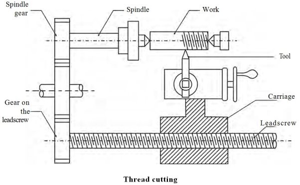
Tool setting for thread cutting operation:
The tool should be set exactly to the height of the center line of the job and at 90 degrees to the job.
Tool setting gauge is used for this purpose.
Feeding during thread cutting operation:
It is done in two ways.
- The tool may be feed exactly at 90 degrees to the job axis but it does not have good cutting action because only the front end of the tool does cutting.
- The tool may beefed at an angle from 27-30 degrees at which the compound rest may be set so that the complete side of the tool is used for cutting action which gives a better polish on the threads.
Job speed during threading:
The job speed will be 1/3 to 1/4th of the job speed in turning operation.
7) Drilling operation:
Drilling is an operation by which we can make holes in a job.
In this operation, the job is rotated at the turning speed on the lathe axis and the drilling tool fitted on the tail-stock spindle. And the tail-stock is moved towards the job by hand feed.
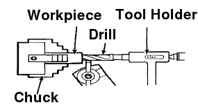
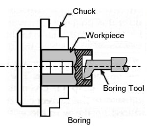
8) Boring operation:
In this operation, we can enlarge the diameter of the existing hole on a job by turning inside with some farm tool known as a boring tool. The boring tool is also fitted on tail-stock.
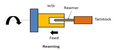
9) Reaming operation:
Reaming is the operation for sizing or finishing a drilled hole to the required size by a tool called reamer. This tool is fitted on tail-stock.
10) Spinning operation:
In this operation, the job of this sheet metal is held between the former and the tail-stock center rotates at high speed with the former. The long round nose forming tool rigidly fixed on special tool post presses the job on the periphery of the former. So the job is taken exactly the shape of the former. This is a chip less machining process.
11) Tapping operation:
We use this operation for creating internal threads within a hole by means of a tool called tap.
Three taps are generally used in an internal thread.
- Taper Tap
- Second Tap
- Plug Tap
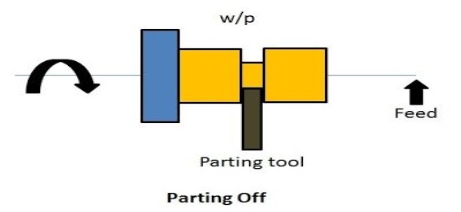
12) Parting-off operation:
It is the operation of cutting off a bar type job after complete the machining process. In this operation a bar type job is held on a chuck, rotates at turning speed, a parting off tool is fed into the job slowly until the tool reaches the center of the job.
Iv) Turning and facing:
Turning:
Turning a taper on a long piece of material is best achieved by offsetting the tailstock. The material is held between two centres as a normal three jaw chuck cannot be used. A three jaw chuck will not hold the material safely or accurately when a long taper is being turned. Diagram ‘A’ below shows the side view of the two centres, the material and the tool post. |
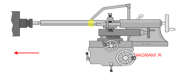 |
Diagram ‘B’ shows a bird’s eye view (plan view) of the same equipment. However, this time it can be seen that the tailstock has been adjusted so that it is off centre. This means that a long taper can be turned. A small amount of material must be removed with each pass of the cutting tool. Also the lathe should be setup so that the cutting tool feeds automatically along the bed of the lathe. This will lead to a better finish to the surface of the material. The animation below shows a 'speeded up version' of taper turning. Normally taper turning takes a long time. |
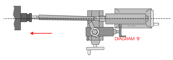 |
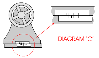
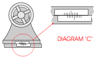
Diagram ‘C’ shows the scale at the back of the tailstock. To adjust the tailstock so that it is off centre usually means loosening a number of Allen screws, offsetting the tailstock and then tightening the screws back in position.
Facing:
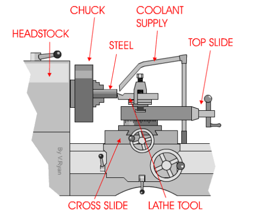
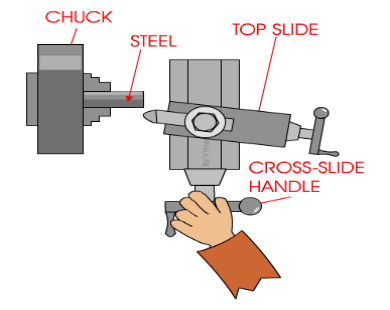
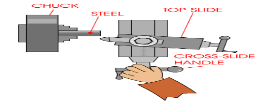
A very basic operation is called ‘facing off’. A piece of steel has been placed in the chuck and the lathe cutting tool is used to level the end. This is done by turning the cross-slide handle so that the cross-slide moves and the cutting tool cuts the surface of the steel. |
 |
Only a small amount of material should be removed - each pass of the cross slide. After each pass of the cutting tool the top slide can be rotated clockwise to move the tool forward approximately 1mm.
This sequence is repeated until the steel has been levelled (faced off).
When using a centre lathe it is always advisable to work patiently and safely. Do not attempt to remove too much material in one go. At best this will caused damage to the steel being worked on and to the expensive cutting tool being used. At worse an accident will occur.
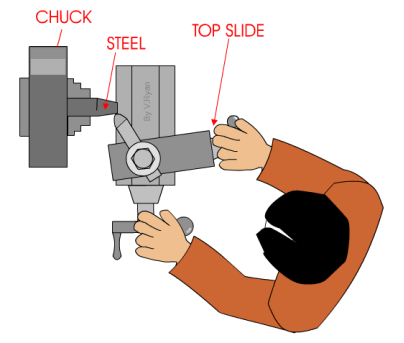
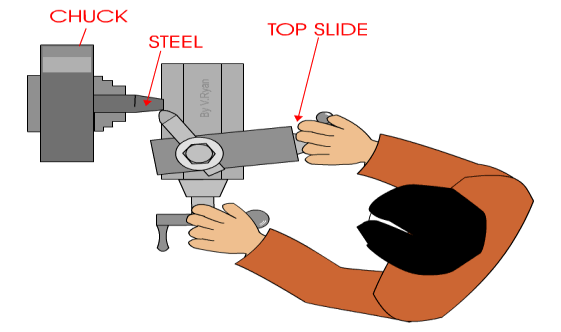
When turning a short taper the top slide is set a the required angle. This is normally done by loosening two small Allen screws and then rotating the topslide to the angle and tightening back up the two allen screws. |
 |
Drilling Machine is the simplest, moderate, and most accurate machine tool used in almost all the production shops and tool rooms. Drilling is basically a single purpose machine tool as its main purpose is to make holes in the workpiece.
A machine consists of a spindle that provides rotary motion to the drilling tool, which finally makes the hole in the job(workpiece).
A drilling machine is a type of machine in which the holes are being made on the workpiece by making use of a rotating tool called drill bit or the twist drill. Drilling is basically a technology of creating holes.
Drilling operation can also be performed on Lathe Machine. In the lathe machine, the workpiece rotates and the drilling tool is held stationary in the tailstock.
Boring: When we talk about drilling, boring is mostly discussed.
Basically, Boring is a process in which the holes are enlarged that is already being drilled or cored. To perform boring action by a machine a special holder for the boring tool is required.
Basic element of pillar drilling machine:
Vertical or Pillar Drilling Machine:
Vertical or Pillar Drilling Machine is free standing and is of a far heavier construction able to take larger drills.
It has a heavy frame to support a wider range of work.
The table height is adjustable and power speed and feeds are available.
The larger drills normally have a taper shank located within taper bore in the spindle end. These tapers are standardized as Morse tapers.
Various parts and their function of the drilling machine are:
1) Bed
2) Pillar
3) Swivel table
4) Motor
5) Steeped pulley
6) Spindle
7) Chuck
8) Drill Bit
9) Hand-wheel
10) Feed Mechanism
11)
1) Bed:
The bed is the main part of the machine on which the whole machine is being mounted. The bed is made up of cast iron, so it has high compressive strength and good wear resistance.
2) Pillar:
The pillar is a type of vertical column that rests on the bed. Pillar is present at the center of the bed. Pillar helps the motor and the spindle head.
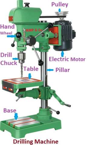
3) Swivel Table:
The table is the place where the workpiece is being mounted. The table is attached to the column and it can be rotated around the column and can have an upward and downward moment. A table can be adjusted at any angle as per the requirement. The worktable is generally made of cast iron and it is mounted on the column. T-slots are provided at the top surface of the table may be in some table there is a vice which also helps to hold the job.
The table can move up and down as also right or left according to the job and tool arrangement. The up and down motion of the table can be given by hand as well as by some electrical mechanism. We use a rack and pinion mechanism for a vertical moment of the table.
The shape of the table can be rectangular or also circular.
4) Motor:
The motor is present at the top of the column. Inside motor shaft is there which is connected to a stepped pulley so that we can increase or decrease the speed of the rotation of the motor.
5) Stepped pulley:
Two steeped pulleys are present on either side of the column at the top. Out of these two, one pulley will be in an upward direction while the other pulley is inverted. Always both the pulleys will be there in the opposite direction. The basic function of the stepped pulley is to control the speed of the rotation of the motor.
6) Spindle:
Spindle arrangement is present at top of the column opposite to the arrangement of the motor. The top of the spindle is attached to one of the stepped pulleys. The bottom of the spindle is connected to the chuck.
7) Chuck:
Chuck is present at the bottom of the spindle. The basic function of the chuck is to hold the cutting tool firmly.
8) Drill bit:
A drill bit is an actual cutting tool that is used to create a hole in the workpiece.
9) Hand Wheel:
The basic function of the hand wheel is to adjust the spindle position as per the requirement.
10) Feed Mechanism:
In a drill machine, we use an electric motor, V-belt, and pulley to transfer the power from the motor to the spindle. For the up and down motion of the drill head, we use hand and as well as automatic feed by an electrical motor. Here also a rack and pinion is used to convert the rotational movement from electrical motor or by hand to the straight-line movement.
Operation of Drilling Machine
The various operations that can be performed in a drilling machine are :
1. Drilling
2. Boring
3. Reaming
4. Counter Boring
5. Counter Sinking
6. Spot Facing
7. Tapping
8. Lapping
9. Grinding
10. Trepanning
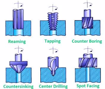
Operation of Drilling Machine
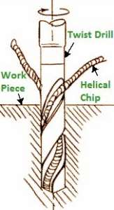
1. Drilling
- Drilling is an operation of producing a cylindrical hole by removing metal by rotating edge of cutting tool call as Drill.
Drilling Operation
- This is one of the simplest methods of producing a hole.
- It doesn’t produce an accurate hole in a workpiece due to the vibration of the spindle and drill.
2. Boring
- The purpose of boring is to enlarge a hole by means of an adjustable cutting tool with only one cutting edge.
- It machine the internal surface of a hole already produced in casting.
- To correct out of roundness of the hole.
- To address the area of the gap as the drilling apparatus follows an autonomous way as for the gap.
3. Reaming
- It is a precise method for estimating and completing an opening which has been recently bored.
- The tool uses for reaming is known as the reamer which has multiple cutting edges.
- It can’t originate a hole.
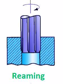
- It basically follows the way which has been recently bored and expels an extremely limited quantity of metal.
- The material removes through this process is around 0.375 mm and for accurate work this should not exceed 0.125 mm.
4. Counter Boring
- This is an operation of enlarging the end of a hole cylindrically.
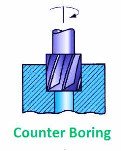
- The enlarged hole forms a square shoulder with the first gap.
- The cutting speed for this operation is 25 % less than that of drilling.
5. Counter Sinking
- It is an activity of making a cone – shaped enlargement of the end of a hole to provide a recess for a flat head screw or countersunk rivet fitted into the hole.
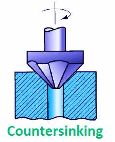
- The standard countersinks have 60°, 82° or 90° included angle and the cutting edges of the tool are formed at the conical surface.
6. Spot Facing
- This is an operation of smoothing and squaring the surface around a hole for the seat for a nut or the head of a screw.
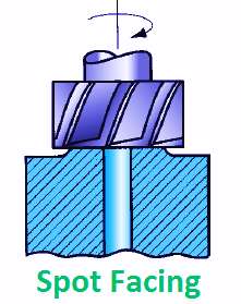
- A counter bore or an extraordinary spot confronting apparatus might be utilized for this reason.
7. Tapping
- This is an operation of cutting internal threads by means of cutting tool called a tap.
- A tap might be considered as a jolt with precise strings cut on it.
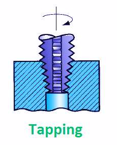
- The threads act as cutting edges which are solidified and ground.
- It removes metal and cuts internal threads which will fit into outer threads of the same size.
8. Lapping
- This is an operation of sizing and finishing a small diameter hole already hardened by removing a very small amount of material by using a lap.
- The lap fits in the hole and moves up and down while it revolves.
9. Grinding
- It is an operation to finish a hardened hole.
- The grinding wheel is made to rotate with the shaft and is exhausted and down.
- The accuracy in grinding operation is quite high about ± 0.1125 mm.
10. Trepanning
- This is an operation of producing a hole by removing metal along the circumference of a hollow cutting tool.
- It performs for producing large holes.

- The tool resembles a hollow tube having cutting edges at one end and a strong shank at the other to fit into the drill spindle.
- This is one of the effective strategies for delivering a hole.
Construction and working
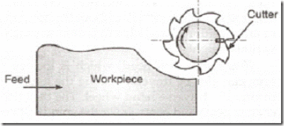
Milling is the cutting operation that removes metal by feeding the work against a rotating, cutter having single or multiple cutting edges. Flat or curved surfaces of many shapes can be machined by milling with good finish and accuracy. A milling machine may also be used for drilling, slotting, making a circular profile and gear cutting by having suitable attachments.
Working Principle: The workpiece is holding on the worktable of the machine. The table movement controls the feed of workpiece against the rotating cutter. The cutter is mounted on a spindle or arbor and revolves at high speed. Except for rotation the cutter has no other motion. As the workpiece advances, the cutter teeth remove the metal from the surface of workpiece and the desired shape is produced.
Horizontal Milling Machine Construction: The main part of machine is base, Column, Knee, Saddle, Table, Overarm, Arbor Support and Elevating Screw.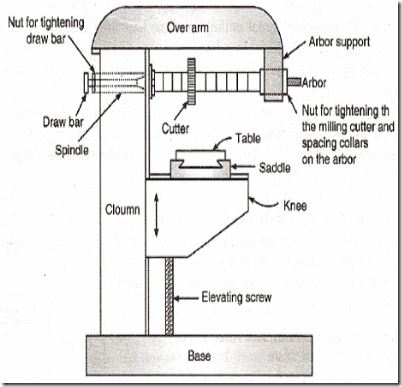
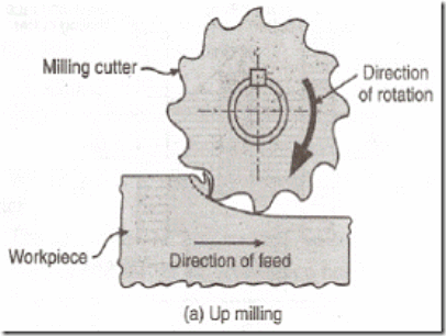
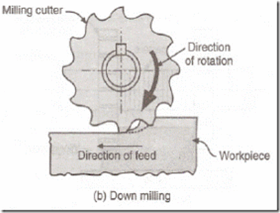
1. Base: It gives support and rigidity to the machine and also acts as a reservoir for the cutting fluids.
2. Column: The column is the main supporting frame mounted vertically on the base. The column is box shaped, heavily ribbed inside and houses all the driving mechanisms for the spindle and table feed
3. Knee: The knee is a rigid casting mounted on the front face of the column. The knee moves vertically along the guide ways and this movement enables to adjust the distance between the cutter and the job mounted on the table. The adjustment is obtained manually or automatically by operating the elevating screw provided below the knee.
4. Saddle: The saddle rests on the knee and constitutes the intermediate part between the knee and the table. The saddle moves transversely, i.e., crosswise (in or out) on guide ways provided on the knee.
5. Table: The table rests on guide ways in the saddle and provides support to the work. The table is made of cast iron, its top surface is accurately machined and carriers T-slots which accommodate the clamping bolt for fixing the work. The worktable and hence the job fitted on it is given motions in three directions:
a). Vertical (up and down) movement provided by raising or lowering the knee.
b). Cross (in or out) or transverse motion provided by moving the saddle in relation to knee.
c). Longitudinal (back and forth) motion provided by hand wheel fitted on the side of feed screw.
In addition to the above motions, the table of a universal milling machine can be swiveled 45° to either side of the centre line and thus fed at an angle to the spindle.
6. Overarm: The Overarm is mounted at the top of the column and is guided in perfect alignment by the machined surfaces. The Overarm is the support for the arbor.
7. Arbor support: The arbor support is fitted to the Overarm and can be clamped at any location on the Overarm. Its function is to align and support various arbors. The arbor is a machined shaft that holds and drives the cutters.
8. Elevating screw: The upward and downward movement to the knee and the table is given by the elevating screw that is operated by hand or an automatic feed.
Operations that can be performed in a Milling Machine:
There are several types of operation that can be performed in a milling machine, and those are:
- Plain Milling Operation
- Face Milling Operation
- End Milling Operation
- For Milling Operation
- T-slot Milling Operation
- Side Milling Operation
- Gear Milling Operation
- Straddle Milling Operation
- Grooves Milling Operation
- Gang Milling Operation
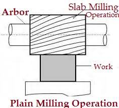
1) Plain Milling Operation:
It is the operation on producing plain, flat, horizontal surface, parallel to the axis of rotation.
This operation is also known as slab milling.
This operation is very common and done in almost all jobs.
This can be carried out on every mill machine.
2) Face milling Operation:
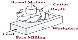
This machining operation is done on the surfaces which are perpendicular to the axis of the cutter. The operation is performed by the face milling cutter mounted on stub arbor of the machine.
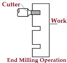
3) End milling operation:
It is the process of producing flat surfaces which may be horizontal, vertical and at an angle taking worktable as a reference.
4. Side milling
- It is the machining process which produces flat vertical surface at the sides of a work piece.
5. Slot milling
- This is a operation of producing slots like T– slots, Plain- slots etc.
6. Angular milling
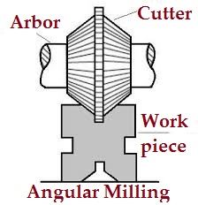
- It is the operation of producing all types of angular cuts like V- notches, grooves, serrations and angular surfaces.
- E.g. Production of V- Blocks, etc.
7. Form milling
- This is the process of machining special contour ( outline ) composed of curves, straight lines, or entirely of curves at a single cut.
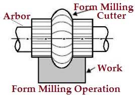
- This operation is accomplish by using convex, concave and corner rounding milling cutters.
- In the wake of machining, the shaped surface is checked by a layout measure.
8. Straddle milling
- It is a process in which two side cutters are use to machining two opposite sides of a work piece simultaneously.
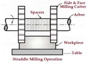
- The Straddle milling is very common to produce square or hexagonal surfaces.
9. Gang milling
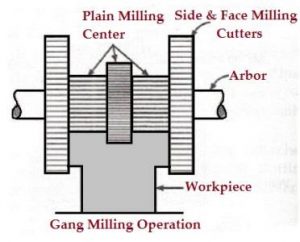
- It is the machining process in which two or more milling cutters are use together to perform different operations simultaneously.
10. Profile milling
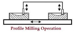
- It is the operation of reproduction of an outline of a template or complex shape of a master die on a work piece.
11. Saw milling
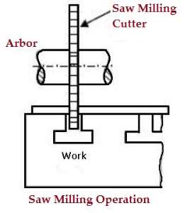
- The Saw milling is the operation of production of a narrow slots or grooves on a work piece by using a saw milling cutter.
12. Gear milling
- The gear cutting operation is performed in a milling machine by using a form relieved cutter.
- The cutter may be cylindrical type or end mill type. The cutter profile corresponds exactly with the tooth space of the gear.
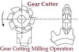
- Similarly separated rigging teeth are cut on an apparatus clear by holding the work on an all inclusive isolating head and afterward ordering it.
13. Helical milling
- The helical milling is the operation of production of helical flutes or grooves around the periphery of a cylindrical or conical work piece.
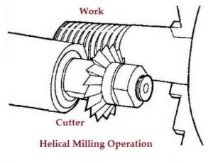
- The usual examples of work performed by helical milling operations are : Production of helical milling cutters, helical gears, cutting helical grooves or flutes on a drill blank or a reamer.
14. Cam milling
- The Cam milling is the operation of production of cams in a milling machine by the use of a universal dividing head and a vertical milling attachment.
- The axis of the cam can be set from zero to ninety degrees in reference to the surface of the table for obtaining different rise of the cam.
- The cams are used to open and close of valves in the internal combustion engines.
15. Thread milling
- The thread milling is operation of production of threads by using a single or multiple threads milling cutter.
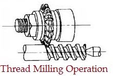
- The operation is performed in special thread milling machines to produce accurate threads in small or large quantities.
The advantages of the Milling machine:
In the milling machine there are following advantages, those are:
- Ideal for the production of individual pieces and small batches.
- Capable of producing complex shapes with the use of multitooth, as well as a single point, cutting tools.
- Operation cost can be very modest given general-purpose equipment and cutters are used.
Milling Machine Disadvantages:
These are the following disadvantages of a milling machine:
- It is more costly than casting, cold forming, extrusion, etc. If these processes can provide the flatness, surface finish and dimensional accuracy required for the part.
- For mass production, it becomes economically necessary to use special-purpose machines.
- They may cost millions of dollars but the cost is justifiable when handling labour which is virtually eliminated and machining accuracy and repeatability is ensured.
The applications of Milling Machine:
These are the following applications of the milling machine:
- This machines used to making gears.
- Usually used to a machined flat surface but can also produce irregular surfaces.
- Used to produce the groove or slot.
- Modern mill machine cut super alloys, titanium, tensile steel to closer tolerance, a greater accuracy, and faster rate.
- This machine is used to design of metal and other materials.
Turning:
Turning a taper on a long piece of material is best achieved by offsetting the tailstock. The material is held between two centres as a normal three jaw chuck cannot be used. A three jaw chuck will not hold the material safely or accurately when a long taper is being turned. Diagram ‘A’ below shows the side view of the two centres, the material and the tool post. |
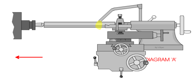 |
Diagram ‘B’ shows a bird’s eye view (plan view) of the same equipment. However, this time it can be seen that the tailstock has been adjusted so that it is off centre. This means that a long taper can be turned. A small amount of material must be removed with each pass of the cutting tool. Also the lathe should be setup so that the cutting tool feeds automatically along the bed of the lathe. This will lead to a better finish to the surface of the material. The animation below shows a 'speeded up version' of taper turning. Normally taper turning takes a long time. |
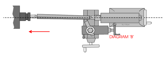 |
Diagram ‘C’ shows the scale at the back of the tailstock. To adjust the tailstock so that it is off centre usually means loosening a number of Allen screws, offsetting the tailstock and then tightening the screws back in position.
Facing:
A very basic operation is called ‘facing off’. A piece of steel has been placed in the chuck and the lathe cutting tool is used to level the end. This is done by turning the cross-slide handle so that the cross-slide moves and the cutting tool cuts the surface of the steel. |
 |
Only a small amount of material should be removed - each pass of the cross slide. After each pass of the cutting tool the top slide can be rotated clockwise to move the tool forward approximately 1mm.
This sequence is repeated until the steel has been levelled (faced off).
When using a centre lathe it is always advisable to work patiently and safely. Do not attempt to remove too much material in one go. At best this will caused damage to the steel being worked on and to the expensive cutting tool being used. At worse an accident will occur.
When turning a short taper the top slide is set a the required angle. This is normally done by loosening two small Allen screws and then rotating the topslide to the angle and tightening back up the two allen screws . |
 |
Operations that can be performed in a Milling Machine:
There are several types of operation that can be performed in a milling machine, and those are:
- Plain Milling Operation
- Face Milling Operation
- End Milling Operation
- For Milling Operation
- T-slot Milling Operation
- Side Milling Operation
- Gear Milling Operation
- Straddle Milling Operation
- Grooves Milling Operation
- Gang Milling Operation
2) Plain Milling Operation:
It is the operation on producing plain, flat, horizontal surface, parallel to the axis of rotation.
This operation is also known as slab milling.
This operation is very common and done in almost all jobs.
This can be carried out on every mill machine.
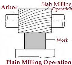
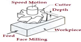
2) Face milling Operation:
This machining operation is done on the surfaces which are perpendicular to the axis of the cutter. The operation is performed by the face milling cutter mounted on stub arbor of the machine.
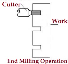
3) End milling operation:
It is the process of producing flat surfaces which may be horizontal, vertical and at an angle taking worktable as a reference.
4. Side milling
- It is the machining process which produces flat vertical surface at the sides of a work piece.
5. Slot milling
- This is a operation of producing slots like T– slots, Plain- slots etc.
6. Angular milling
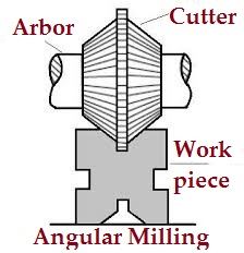
- It is the operation of producing all types of angular cuts like V- notches, grooves, serrations and angular surfaces.
- E.g. Production of V- Blocks, etc.
7. Form milling
- This is the process of machining special contour ( outline ) composed of curves, straight lines, or entirely of curves at a single cut.
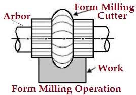
- This operation is accomplish by using convex, concave and corner rounding milling cutters.
- In the wake of machining, the shaped surface is checked by a layout measure.
8. Straddle milling
- It is a process in which two side cutters are use to machining two opposite sides of a work piece simultaneously.
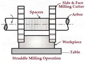
- The Straddle milling is very common to produce square or hexagonal surfaces.
9. Gang milling
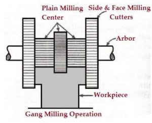
- It is the machining process in which two or more milling cutters are use together to perform different operations simultaneously.
10. Profile milling
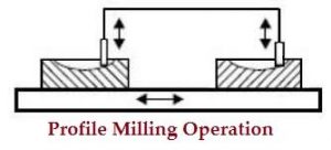
- It is the operation of reproduction of an outline of a template or complex shape of a master die on a work piece.
11. Saw milling
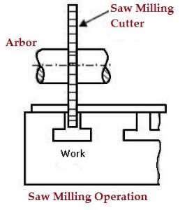
- The Saw milling is the operation of production of a narrow slots or grooves on a work piece by using a saw milling cutter.
12. Gear milling
- The gear cutting operation is performed in a milling machine by using a form relieved cutter.
- The cutter may be cylindrical type or end mill type. The cutter profile corresponds exactly with the tooth space of the gear.
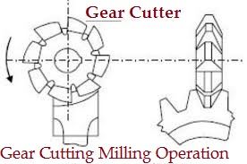
- Similarly separated rigging teeth are cut on an apparatus clear by holding the work on an all inclusive isolating head and afterward ordering it.
13. Helical milling
- The helical milling is the operation of production of helical flutes or grooves around the periphery of a cylindrical or conical work piece.
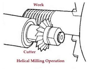
- The usual examples of work performed by helical milling operations are : Production of helical milling cutters, helical gears, cutting helical grooves or flutes on a drill blank or a reamer.
. Drilling
- Drilling is an operation of producing a cylindrical hole by removing metal by rotating edge of cutting tool call as Drill.
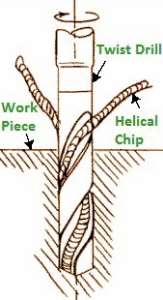
Drilling Operation
- This is one of the simplest methods of producing a hole.
- It doesn’t produce an accurate hole in a workpiece due to the vibration of the spindle and drill.
2. Boring
- The purpose of boring is to enlarge a hole by means of an adjustable cutting tool with only one cutting edge.
- It machine the internal surface of a hole already produced in casting.
- To correct out of roundness of the hole.
- To address the area of the gap as the drilling apparatus follows an autonomous way as for the gap.
3. Reaming
- It is a precise method for estimating and completing an opening which has been recently bored.
- The tool uses for reaming is known as the reamer which has multiple cutting edges.
- It can’t originate a hole.
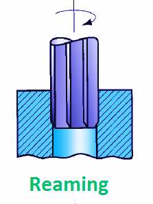
- It basically follows the way which has been recently bored and expels an extremely limited quantity of metal.
- The material removes through this process is around 0.375 mm and for accurate work this should not exceed 0.125 mm.
Casting is the process of creating metal objects by pouring liquid metal into molds, where it cools and hardens into the mold’s shape. Although the premise is simple, there are many variations in metal casting methods. To take an object from idea to reality, designers must specify the physical and aesthetic needs of the final product and from there find the simplest way to produce those qualities. The complexity of the design, as well as what stresses the final object must withstand, help determine the metal; how the metal behaves in liquid, solid, and cooling states will dictate requirements for the mold. Good casting design is a matter of knowing all the ingredients and processes involved to get to the final product.
Metalworkers have used the same casting processes for millennia, with the first castings dating back to the 4th century BC in China. Even with this long history, the foundry is a place of development and innovation. In this fourteen-week series we will explore all the steps in making a casting, and what factors influence the choice of method or design, from ancient wisdom to the modern-day advances.
We explore the following stages of the metal casting process:
- Metal Casting Design
During the design phase, engineers select both the metal and molding method to produce the necessary physical properties and appearance of the final product. - Rapid Prototyping
Advances in 3D printing have changed the way products are prototyped and produced. - Metal Casting Methods
Methods for metal casting are divided into two broad categories of reusable or non-reusable molds. - Sand Casting
Sand casting into non-reusable green sand molds is the oldest form of metal casting, and is still the most common form used today. - Patternmaking
Patterns are the prototype objects used to create molds. They must be designed to be removed from the mold without disturbing it, as well as with the behavior of the metal while pouring and cooling in mind. - Foundry Sand
Green sand is the most common type of sand used in sand casting, but additions to foundry sand change the final casting appearance. - Coremaking
Cores are inserts used to shape a casting’s interior, creating spaces that aren’t shaped by the pattern. - Melting and Pouring
Melting, mixing, and pouring metals at temperatures near 2800°F is a dangerous job that requires specialized equipment and careful work. - Shakeout and Cleaning
Shakeout is the process of removing sand from castings. This can be done manually or mechanized with tumblers, tables, or blast cleaning unites. - Heat Treatment
Heat treatment changes metal on a molecular level, affecting its mechanical properties. It is often used to make metal less brittle. - Inspection
In a variety of ways, the metals used in a set of castings, and the castings themselves can be quality assured. Materials analysis studies the properties and composition of the metal, while both destructive and non-destructive testing looks for shrinkage or casting defects. - Secondary Processing
Machining removes some of the flashing necessary for the mold, and can provide both smooth finishing and fine details. For items that need precision shapes, machining is often the final step.
WHAT IS A FOUNDRY?
A foundry is a factory that produces metal castings. Our comprehensive resource page “What is a Foundry” explores the design, machinery, and safety requirements of foundries.