Unit - 1
Drawing Standards and Geometrical Construction

Figure 1
Lines of different types and thicknesses are used for graphical representation of objects. The types of lines and their applications are shown in Table 1.1. Typical applications of different types of lines are shown in Figs. 2
Table 1
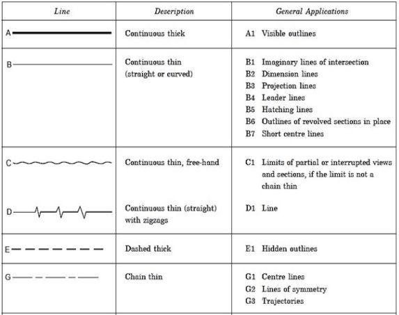
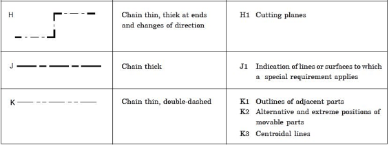
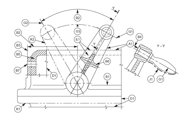
Figure 2
Thickness of Lines
Two thicknesses of lines are used in draughting practice. The ratio of the thick to thin line should not be less than 2:1. The thickness of lines should be chosen according to the size and type of the drawing from the following range: 0.18, 0.25, 0.35, 0.5, 0.7, 1, 1.4 and 2
It is recommended that the space between two parallel lines, including hatching, should never be less than 0.7 mm.
Order of priority of coinciding lines:
When two or more lines of different types coincide, the following order of priority should be observed:
(i) Visible outlines and edges (Continuous thick lines, type A),
(ii) Hidden outlines and edges (Dashed line, type E or F),
(iii) Cutting planes (Chain thin, thick at ends and changes of cutting planes, type H),
(iv) Centre lines and lines of symmetry (Chain thin line, type G),
(v) Centroidal lines (Chain thin double dashed line, type K),
(vi) Projection lines (Continuous thin line, type B).
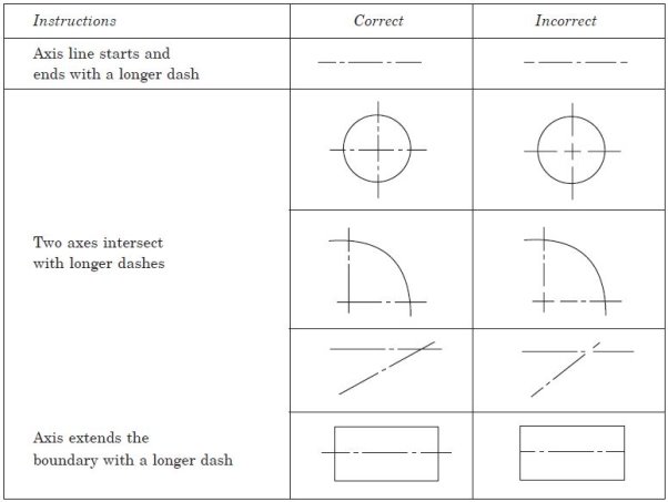
The invisible line technique and axis representation should be followed as per the
Recommendations given in Table 2
Table 2
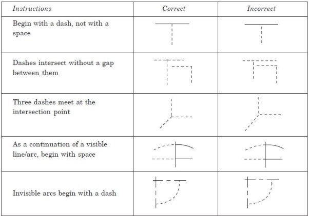
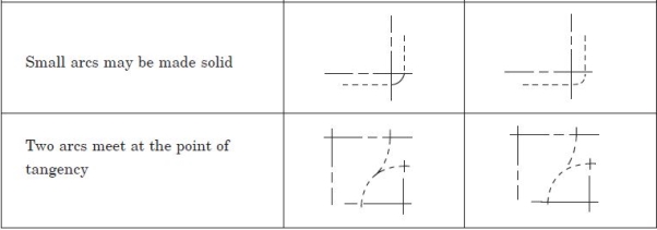
Table 3
Termination of leader lines:
A leader is a line referring to a feature (dimension, object, outline, etc.).
Leader lines should terminate (Fig. 3),
(a) with a dot, if they end within the outlines of an object,
(b) with an arrowhead, if they end on the outline of an object,
(c) without dot or arrowhead if they end on a dimension line.

Figure 3
Lettering
The essential features of lettering on technical drawings are legibility, uniformity, and suitability for microfilming and other photographic reproductions. To meet these requirements, the characters are to be clearly distinguishable from each other to avoid any confusion between them, even in the case of slight mutilations. The reproductions require the distance between two adjacent lines or the space between letters to be at least equal to twice the line thickness (Fig. 4). The line thickness for lower case and capital letters shall be the same to facilitate lettering.
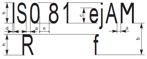
Figure 4
Dimensioning:
A drawing of a component, in addition to providing complete shape description, must also furnish information regarding the size description. These are provided through the distances between the surfaces, location of holes, nature of surface finish, type of material, etc. The expression of these features on a drawing, using lines, symbols, figures, and notes is called dimensioning.
General Principles:
Dimension is a numerical value expressed in appropriate units of measurement and indicated on drawings, using lines, symbols, notes, etc., so that all features are completely defined.
1. As far as possible, dimensions should be placed outside the view.
2. Dimensions should be taken from visible outlines rather than from hidden lines.
3. Dimensioning to a centre line should be avoided except when the centre line passes
Through the centre of a hole.
4. Each feature should be dimensioned once only on a drawing.
5. Dimensions should be placed on the view or section that relates most clearly to the
Corresponding features.
6. Each drawing should use the same unit for all dimensions, but without showing the
Unit symbol.
7. No more dimensions than are necessary to define a part should be shown on a drawing.
8. No features of a part should be defined by more than one dimension in any one direction.
Method of execution:
The elements of dimensioning include the projection line, dimension line, leader line, dimension line termination, the origin indication and the dimension itself. The various elements of dimensioning are shown in Figs. 5 and 6. The following are some of the principles to be adopted during execution of dimensioning:

Figure 5

Figure 6
1. Projection and dimension lines should be drawn as thin continuous lines.
2. Projection lines should extend slightly beyond the respective dimension lines.
3. Projection lines should be drawn perpendicular to the feature being dimensioned. Where necessary, they may be drawn obliquely, but parallel to each other (Fig. 7). However, they must be in contact with the feature.
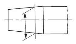
Figure 7
4. Projection lines and dimension lines should not cross each other unless it is unavoidable (Fig. 8).
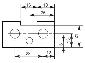
Figure 8
5. A dimension line should be shown unbroken, even where the feature to which it refers, is shown broken (Fig. 9).
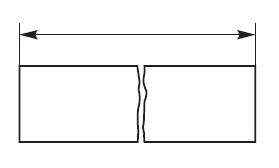
Figure 9
6. A centre line or the outline of a part should not be used as a dimension line, but may
Be used in place of projection line (Fig. 8).
Method of indicating Dimensions:
Dimensions should be shown on drawings in characters of sufficient size, to ensure complete legibility. They should be placed in such a way that they are not crossed or separated by any other line on the drawing. Dimensions should be indicated on a drawing, according to one of the following two methods. However, only one method should be used on anyone drawing.
METHOD–1 (Aligned System)
Dimensions should be placed parallel to their dimension lines and preferably near the middle, above and clear-off the dimension line (Fig. 10).
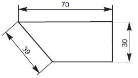
Figure 10
Dimensions may be written so that they can be read from the bottom or from the right side of the drawing. Dimensions on oblique dimension lines should be oriented as shown in Fig. 11. Angular dimensions may be oriented as shown in Fig. 12.
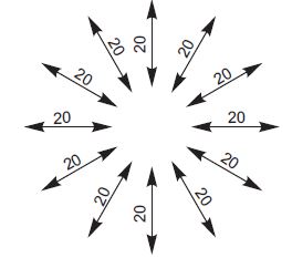
Figure 11
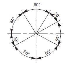
Figure 12
Chain Dimensions:
Chains of single dimensions should be used only where the possible accumulation of tolerances does not endanger the functional requirement of the part (Fig. 13).
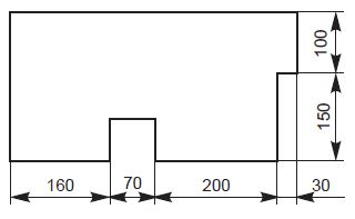
Figure 13
Scaling convention:
Scale is the ratio of the linear dimension of an element of an object as represented in the
Drawing, to the real linear dimension of the same element of the object itself. Wherever possible,
It is desirable to make full size drawings, to represent true shapes and sizes. If this is not
Practicable, the largest possible scale should be used. While drawing exceedingly small objects, such
As watch components and other similar objects, it is advisable to use enlarging scales.
If all drawings are made to the same scale, the scale should be indicated in or near the title
Block. Where it is necessary to use more than one scale on a drawing, the main scale only
Should be shown in the title block and all the other scales, adjacent to the item reference
Number of the part concerned or near the drawings.
Scaling designation:
The complete designation of a scale should consist of the word Scale, followed by the indication
Of its ratio as:
SCALE 1: 1 for full size,
SCALE ×: 1 for enlarged scales,
SCALE 1: × for reduced scales.
The designation of the scale used on the drawing should be shown in the title block.
Recommended scales:
The recommended scales for use on technical drawings are given in Table 4. The scale and the size of the object in turn, will decide the size of the drawing.
Table 4

To divide a given straight line into any number of equal parts
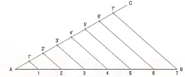
Figure 14
Let AB be the given line to be divided into say, seven equal parts.
(i) Draw the line AB of given length.
(ii) Draw another line AC making an angle of less than 30° with AB.
(iii) With the help of dividers mark 7 equal parts of any suitable length on line AC
And mark them by points 1 ', 2', 3', 4', 5', 6' and 7' as shown.
(iv) Join the last point 7' with point B of the line AB.
(v) Now, from each of the other marked points 6', 5' 4', 3', 2' and 1 ', draw lines
Parallel to 7'8 cutting the line AB at 6, 5, 4, 3, 2 and 1 respectively.
(vi) Now the line AB has been divided into 7 equal parts. You can verify this by
Measuring the lengths.
TO bisect an angle
Let ABC be the given angle.
(i) With B as centre and any radius, draw an arc cutting AB at D and BC at E.
(ii) With centres D and E and the same or any convenient radius, draw arcs intersecting each other at F.
(iii) Draw a line joining B and F. BF bisects the angle ABC, i.e. ∠ABF = ∠ FBC.
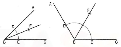
Figure 15
To construct a regular polygon, given the length of its side.
(i) Draw a line AB equal to the given length.
(ii) With centre A and radius AB, draw a semi-circle BP.
(iii) With a divider, divide the semi-circle into seven equal parts (same as the
Number of sides). Number the division-points as 1, 2, etc. starting from P.
(iv) Draw a line joining A with the second division-point 2.
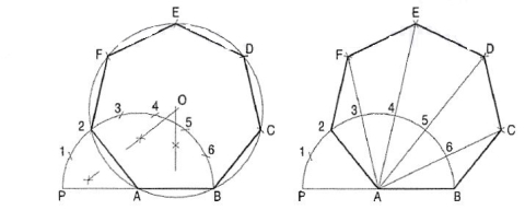
Figure 16
(a) Inscribe circle method (fig. 16).
(i) Draw perpendicular bisectors of A2 and AB intersecting each other at 0.
(ii) With centre O and radius OA, describe a circle.
(iii) With radius AB and starting from B, cut the circle at points, C, D ..... 2.
(iv) Draw lines BC, CD etc. thus completing the required heptagon.
(b) Arc method (fig. 16).
(i) With centre B and radius AB, draw an arc cutting the line A6-produced at C.
(ii) With centre C and the same radius, draw an arc cutting the line AS produced at D.
(iii) Find points E and F in the same manner.
(iv) Draw lines BC, CD etc. and complete the heptagon.
To construct a pentagon, length of a side given.
Method I: (fig.17):
(i) Draw a line AB equal to the given length.
(ii) With centre A and radius AB, describe a circle 1.
(iii) With centre B and the same radius, describe a circle-2 cutting circle-1 at C and D.
(iv) With centre C and the same radius, draw an arc to cut circle-1 and circle-2 at E and F respectively.
(v) Draw a perpendicular bisector of the line AB to cut the arc ff at G.
(vi) Draw a line EC and produce it to cut Q circle-2 at P.
(vii) Draw a line FG and produce it to cut circle-1 at R.
(viii) With P and Ras centres and AB as radius, draw arcs intersecting each other at Q.
(ix) Draw lines BP, PQ, QR and RA, thus completing the pentagon.
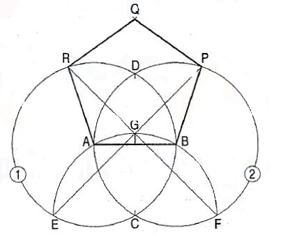
Figure 17
Method II: (fig. 18)
(i) Draw a line AB equal to the given length. B E
(ii) Bisect AB in a point C.
(iii) Draw a line BD perpendicular and equal to AB.
(iv) With centre C and radius CD, draw an arc to intersect the line AB-produced at E.
(v) Then AE is the length of the diagonal of the pentagon.
(vi) Therefore, with centre A and radius AB, draw an arc intersecting the arc drawn with centre B and radius AE at R.
(vii) Again, with centre A and radius AE, draw an arc intersecting the arc drawn with centre B and radius AB at P.
(viii) With centres A and B and radius AE, draw arcs intersecting each other at Q.
(ix) Draw lines BP, PQ, QR and RA, thus completing the pentagon.
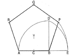
Figure 18
Reference/Text Books
1. N. D. Bhatt, Engineering Drawing, Charotar Publishing House, 46th Edition, 2003.
2. K. V. Nataraajan, A text book of Engineering Graphic, Dhanalakshmi Publishers, Chennai, 2006.
3. K. Venugopal and V. Prabhu Raja, Engineering Graphics, New Age International (P) Ltd, 2008.
4. Dhananjay A. Jolhe, Engineering Drawing with an Introduction to Autocad, McGraw Hill Education, 2017